fuse chart RENAULT TWINGO 2009 2.G Chasiss ABS Workshop Manual
[x] Cancel search | Manufacturer: RENAULT, Model Year: 2009, Model line: TWINGO, Model: RENAULT TWINGO 2009 2.GPages: 76
Page 4 of 76

38C-4
MR-413-X44-38C000$047_eng.mif
V1
MK70 ABS
Vdiag No: 04ANTI-LOCK BRAKING SYSTEM
Fault finding - Introduction38C
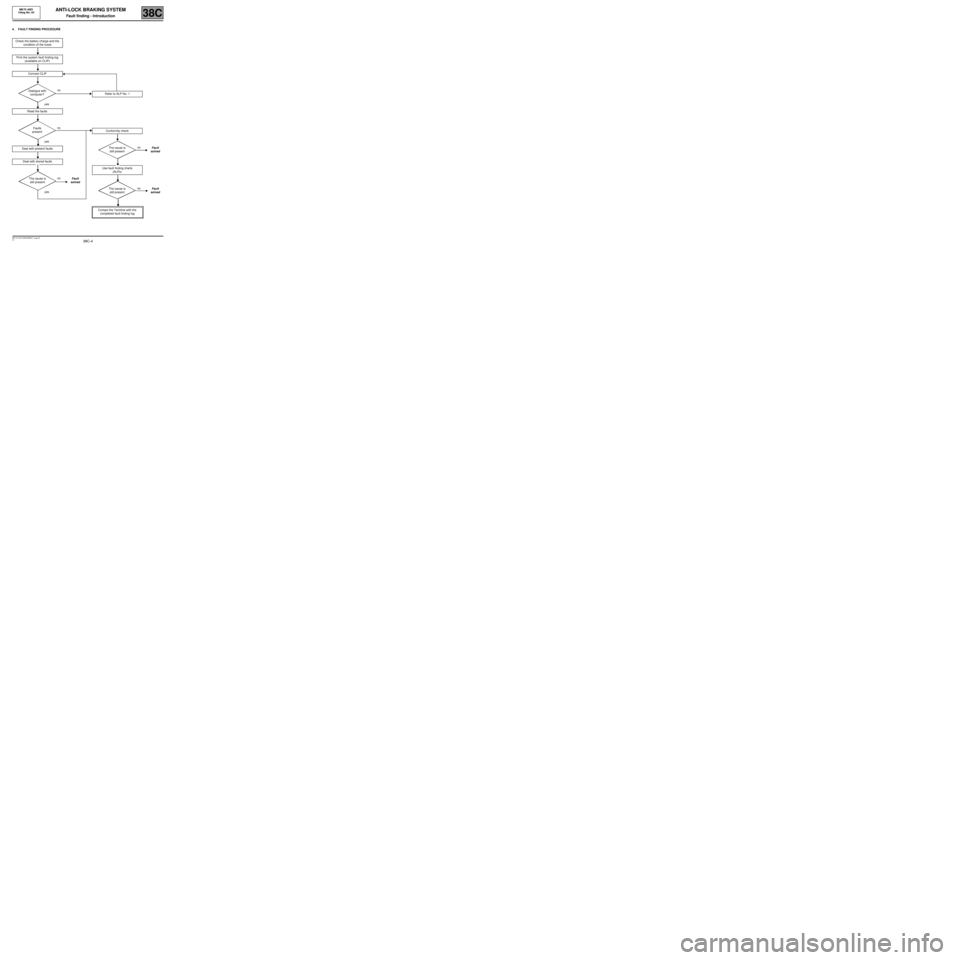
4. FAULT FINDING PROCEDURE
Check the battery charge and the
condition of the fuses
Print the system fault finding log
(available on CLIP)
Connect CLIP
no
Dialogue with
computer?
yes
Read the faults
no
Faults
present
yes
Deal with present faults
Deal with stored faults
no
The cause is
still presentFault
solved
yes
Refer to ALP No. 1
Conformity check
no
The cause is
still presentFault
solved
Use fault finding charts
(ALPs)
no
The cause is
still presentFault
solved
Contact the Techline with the
completed fault finding log
Page 65 of 76

38C-65
MR-413-X44-38C000$940_eng.mif
V1
38C
ANTI-LOCK BRAKING SYSTEM
Fault finding - Fault Finding Chart
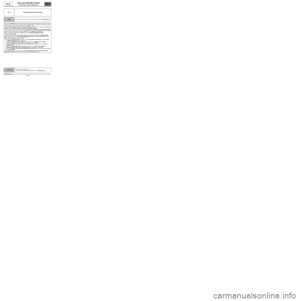
ALP 1 No dialogue with the ABS computer
NOTESOnly consult this customer complaint after a complete check with the diagnostic tool.
Check that the diagnostic tool is not causing the fault by trying to establish dialogue with a computer on another
vehicle. If the tool is not at fault, and dialogue cannot be established with any other computer on the same vehicle,
the cause could be a faulty computer interfering on the multiplex network.
Check the battery voltage and carry out the necessary operations to obtain the correct voltage (9.5 V < Battery
voltage < 17.5 V, see MR411 Mechanical systems, 16A, Starting-charging).
Run fault finding on the multiplex network, using the diagnostic tool (see MR413 Fault finding, 88B, Multiplex).
Check the condition and position of the 15A and 20A fuses in the engine fuse and relay box.
Check the condition and position of the F10 5 A fuse in the Passenger compartment fuse box.
Consult section 81C, Fuses.
Check the connection and condition (possible damage to the wiring) of the connector of component 1094.
If the connector is faulty (see Technical Note 6015A, Repairing electrical wiring, wiring: Precautions for
repair), repair the connector, otherwise replace the wiring.
Check that the supply to the computer is correct:
●Connector of component 1094 disconnected, check the insulation and continuity of connection MAH
of component 1094 (tightness, oxidisation etc.).
●Connectors of component 1094 and R107 disconnected, check the insulation and continuity of
connection AP5 between component 1094 and intermediate connector R107.
●Check the insulation and continuity of connection AP5 between intermediate connector R107 and
component 1016.
●Connectors of component 1094 and R67 disconnected, check the insulation and continuity of
connections BP8 and BP14 between component 1094 and intermediate connector R67.
●Check the insulation and continuity of connections BP8 and BP14 between intermediate connector R67
and component 597.
If the connection or connections are faulty (see Technical Note 6015A, Electrical wiring repair, Wiring:
Precautions for repair), repair the connectors or wiring, otherwise replace the wiring.
AFTER REPAIRClear the computer fault memory.
Carry out a road test followed by another check with the diagnostic tool.
ABS_V04_ALP1
MK70 ABS
Vdiag No: 04
MR-413-X44-38C000$940_eng.mif
Page 66 of 76

38C-66
MR-413-X44-38C000$940_eng.mif
V1
ANTI-LOCK BRAKING SYSTEM
Fault finding - Fault Finding Chart
MK70 ABS
Vdiag No: 04
38C
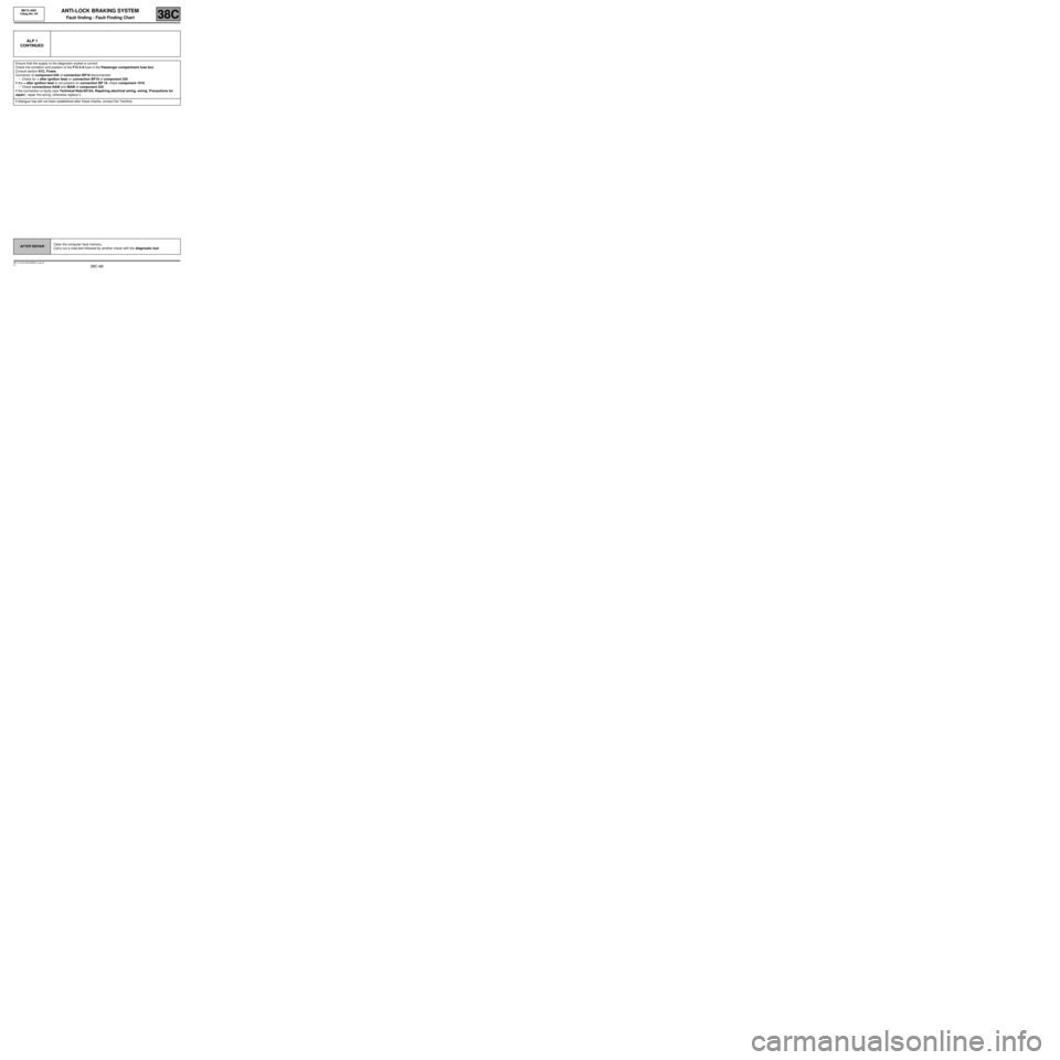
ALP 1
CONTINUED
Ensure that the supply to the diagnostic socket is correct:
Check the condition and position of the F12 5 A fuse in the Passenger compartment fuse box.
Consult section 81C, Fuses.
Connector of component 645 of connection BP19 disconnected:
–Check for + after ignition feed on connection BP19 of component 225.
If the + after ignition feed is not present on connection BP 19, check component 1016.
–Check connections NAM and MAM of component 225.
If the connection is faulty (see Technical Note 6015A, Repairing electrical wiring, wiring: Precautions for
repair), repair the wiring, otherwise replace it.
If dialogue has still not been established after these checks, contact the Techline.
AFTER REPAIRClear the computer fault memory.
Carry out a road test followed by another check with the diagnostic tool.