brakes RENAULT TWINGO 2009 2.G Chasiss ESP Workshop Manual
[x] Cancel search | Manufacturer: RENAULT, Model Year: 2009, Model line: TWINGO, Model: RENAULT TWINGO 2009 2.GPages: 101
Page 9 of 101

38C -9V3 MR-413-X44-38C050$020.mif
Bosch 8.1 ESP
Vdiag No.: 05
38C
The computer/hydraulic unit assembly:
–Located to the left of the bulkhead in the engine compartment.
Front wheel sensors:
–Screwed into the stub-axle, each front sensor has an intermediate connector located behind the plastic wheel arch
liner.
Rear wheel sensor intermediate connectors:
–Located in a sealed unit under the vehicle.
Rear wheel sensors:
–Screwed into the rear brake drum flange (For vehicles equipped with drum brakes).
–Clipped onto the sensor mounting (For vehicles equipped with disc brakes).
Brake light switch:
–Located on the pedal assembly.
Lateral acceleration and yaw speed sensor:
–Located under the passenger seat
ANTI-LOCK BRAKING SYSTEM
Fault finding – List and location of components
Page 12 of 101
38C-12V3 MR-413-X44-38C050$040.mif
38C
Bosch 8.1 ESP
Vdiag No.: 05
EBD (electronic braking distribution):
The electronic braking distribution unit optimises the brakeforce distribution between the front and rear axles.
This function ensures vehicle stability under braking.
ABS (anti-lock braking system):
The ABS prevents the wheels from locking when braking. This function allows the vehicle to be steered under
braking and ensures vehicle stability under braking.
MSR (engine torque control):
This is a function that enhances the ABS function. Its purpose is to prevent the drive wheels from spinning
excessively when lifting off the accelerator or changing down a gear on a low grip surface, by requesting the engine
management to regulate the driving torque of the engine (resisting torque compensation) to "relaunch" the wheels.
ASR (wheel traction control):
This function keeps the drive wheels from slipping during starting or acceleration.
The system brakes the wheel in a slippage situation to maintain full traction.
ESP: Electronic stability program:
The ESP guarantees within physical limits the dynamic stability of the vehicle by checking and correcting oversteer.
In any case, the ESP system does not intervene in place of the driver. Using data from the steering wheel, it merely
makes vehicle handling truer to the driver's intention.
CDC (Dynamic Driving Control):
The Dynamic Driving Control guarantees vehicle steerability within physical limits by checking and correcting
understeer.
The Dynamic Driving Control is an advancement of the ESP system and has same objective: to maintain vehicle
control in all operating situations.
The ESP computer supplies the other computers with information on the vehicle speed via a wire connection for the
radio, the power-assisted steering and the electric sunroof, and via the multiplex network for the other computers.
The ESP computer also supplies the multiplex network with the odometry for the instrument panel and navigation
system.
If heavy braking produces very rapid deceleration, the ESP computer issues a request to the UCH (passenger
compartment connection unit) via the multiplex network asking it to switch on the hazard warning lights (depending
on the law in the relevant country).
ANTI-LOCK BRAKING SYSTEM
Fault finding – Features
Page 25 of 101
38C-25
AFTER REPAIRClear the computer fault memory.
Carry out a road test followed by another check with the diagnostic tool
If the fault is still present, contact the Techline.
V3 MR-413-X44-38C050$101.mif
ANTI-LOCK BRAKING SYSTEM
Fault finding – Interpretation of faults38C
Bosch 8.1 ESP
Vdiag No.: 05
DF007
CONTINUED 1
2.DEFNOTESConditions for applying the fault finding procedure to
stored faults:
The fault is declared present after a road test.
Check the connection and condition (possible wiring damage) of the connectors of components 1094 and 151.
If the connector is faulty (see Technical Note 6015A, Repairing electrical wiring, Wiring: Precautions
for repair), repair the connector, otherwise replace the wiring.
Check the insulation and continuity of connections 4G and 4H between components 151 and 1094.
Also check the insulation between these 2 connections.
If the connection or connections are faulty (see Technical Note 6015A, Repairing electrical wiring, Wiring:
Precautions for repair), repair the wiring, otherwise replace it.
Inspect the condition of the target (metallic contamination etc.).
Clean the target with compressed air if necessary.
For versions equipped with disc brakes:
Check the sensor / target air gap through one wheel revolution (0.1 < rear wheel air gap < 0.9 mm).
If the air gap is incorrect:
–Replace the instrumented bearing/wheel sensor mounting assembly (see MR 411, Mechanical, 33A, Rear axle
components, Rear hub carrier bearing: Removal - Refitting).
Page 26 of 101
38C-26
AFTER REPAIRClear the computer fault memory.
Carry out a road test followed by another check with the diagnostic tool
If the fault is still present, contact the Techline.
V3 MR-413-X44-38C050$101.mif
ANTI-LOCK BRAKING SYSTEM
Fault finding – Interpretation of faults38C
Bosch 8.1 ESP
Vdiag No.: 05
DF007
CONTINUED 2
If the air gap is correct:
–Swap both rear wheel brake discs as well as the brake pads.
–Clear the computer fault memory.
–Carry out a road test followed by another check with the diagnostic tool.
–If the fault initially declared as DF007 has become DF027 Rear right-hand wheel speed sensor circuit,
replace the instrumented bearing/wheel sensor mounting assembly (see MR 411, Mechanical, 33A, Rear axle
components, Rear hub carrier bearing: Removal - Refitting).
–If the fault remains on the same side, replace component 151 (see MR 411, Mechanical, 38C, Anti-lock
braking system, Rear wheel speed sensor, Removal - Refitting).
For versions equipped with drum brakes:
–Swap both rear wheel brake drums.
–Clear the computer fault memory.
–Carry out a road test followed by another check with the diagnostic tool.
–If the fault initially declared as DF007 has become DF027 Rear right-hand wheel speed sensor circuit, replace
the target (see MR 411, Mechanical, 33A, Rear axle components, Rear brake drums, Removal - Refitting).
–If the fault remains on the same side, replace component 151 (see MR 411, Mechanical, 38C, Anti-lock
braking system, Rear wheel speed sensor, Removal - Refitting).
Page 33 of 101
38C-33
AFTER REPAIRClear the computer fault memory.
Carry out a road test followed by another check with the diagnostic tool
If the fault is still present, contact the Techline.
V3 MR-413-X44-38C050$101.mif
ANTI-LOCK BRAKING SYSTEM
Fault finding – Interpretation of faults38C
Bosch 8.1 ESP
Vdiag No.: 05
DF027
CONTINUED
2.DEFNOTESConditions for applying the fault finding procedure to
stored faults:
The fault is declared present after a road test.
Check the connection and condition (possible wiring damage) of the connectors ofcomponents 1 094and150.
Iftheconnector is faulty (seeTe chnical Note 6015A, Repairing e lectrical wiring, Wiring: Precautions for repair),
repair the connector, otherwise replace the wiring.
Ch eck the insulation and continuity ofconnections 4Sand4Tbetweencomponents 150and1094.
Alsocheckthe insulationbetween these 2 connections.
Iftheconnection or connections are faulty (seeTe chnical Note 6015A, Repairing e lectrical wiring, Wiring:
Precautions for repair), repair the wiring, otherwise replace it.
Inspect the condition of the target ( metallic contamination etc.).
Cleanthetarget with compressed air if necessary.
For v ersions e quippedwithdiscbrakes:
Check the sensor/target air gap through one wheel revolution (0.1 mm
–Replace the instrumented bearing/wheel sensor mounting assembly (see MR 411, Mechanical, 33A, Rear axle
components, Rear hub carrier bearing: Removal - Refitting).
If the air gap iscorrect:
–Swap both rear wheel brake discs as well as the brake pads.
–Clear the computer fault memory.
–Carry out a road test followed by another check with the diagnostic tool.
–If the fault initially declared as DF007 Rear left-hand wheel speed sensor circuit has become DF027, replace
the instrumented bearing/wheel sensor mounting assembly (see MR 411, Mechanical, 33A, Rear axle
components, Rear hub carrier bearing: Removal - Refitting).
–If the fault remains on the same side, replace component 150 (see MR 411, Mechanical, 38C, Anti-lock
braking system, Rear wheel speed sensor, Removal - Refitting).
For v ersions e quippedwithdrumbrakes:
–Swap both rear wheel brake drums.
–Clear the computer fault memory.
–Carry out a road test followed by another check with the diagnostic tool.
–If the fault initially declared as DF007 Rear left-hand wheel speed sensor circuit has become DF027, replace
the target (see MR 411, Mechanical, 33A, Rear axle components, Rear brake drums, Removal - Refitting).
–If the fault remains on the same side, replace component 150 (see MR 411, Mechanical, 38C, Anti-lock
braking system, Rear wheel speed sensor, Removal - Refitting).
Page 45 of 101
38C-45
AFTER REPAIRClear the computer fault memory.
Carry out a road test followed by another check with the diagnostic tool
If the fault is still present, contact the Techline.
V3 MR-413-X44-38C050$101.mif
ANTI-LOCK BRAKING SYSTEM
Fault finding – Interpretation of faults38C
Bosch 8.1 ESP
Vdiag No.: 05
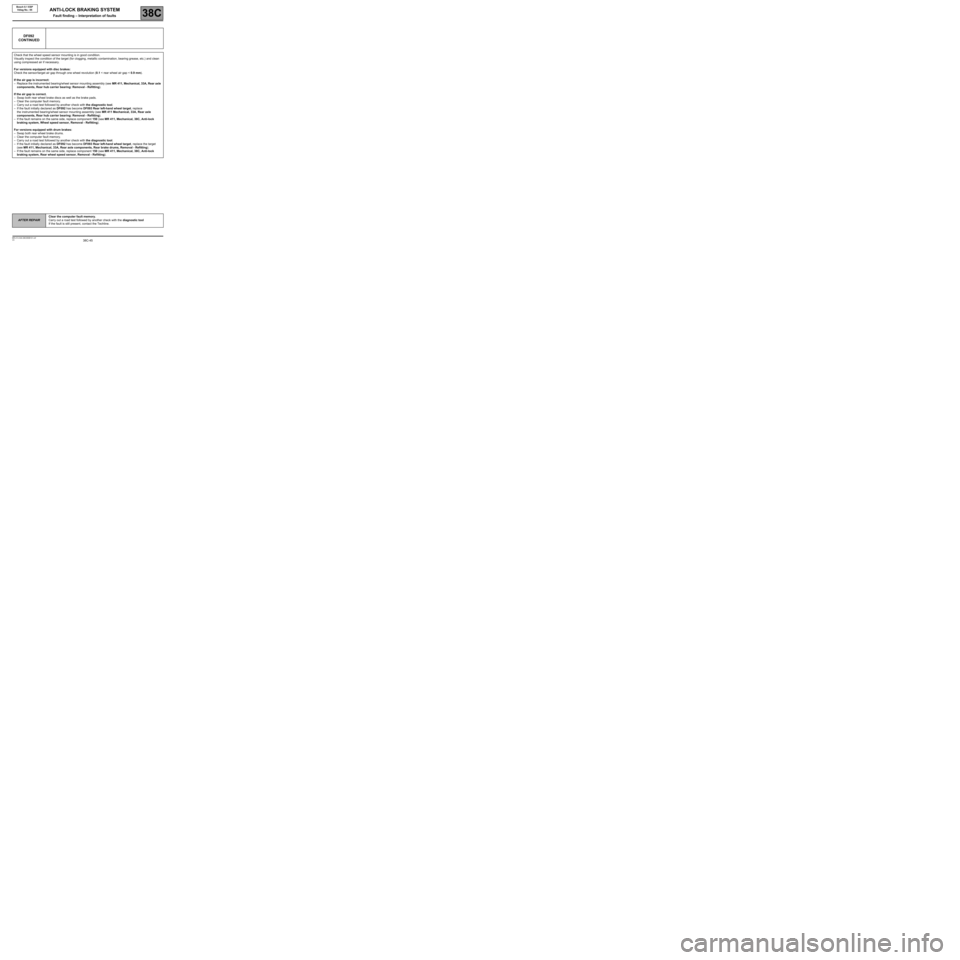
DF092
CONTINUED
Check that the wheel speed sensor mounting is in good condition.
Visually inspect the condition of the target (for clogging, metallic contamination, bearing grease, etc.) and clean
using compressed air if necessary.
For versions equipped with disc brakes:
Check the sensor/target air gap through one wheel revolution (0.1 < rear wheel air gap < 0.9 mm).
If the air gap is incorrect:
–Replace the instrumented bearing/wheel sensor mounting assembly (see MR 411, Mechanical, 33A, Rear axle
components, Rear hub carrier bearing: Removal - Refitting).
If the air gap is correct.
–Swap both rear wheel brake discs as well as the brake pads.
–Clear the computer fault memory.
–Carry out a road test followed by another check with the diagnostic tool.
–If the fault initially declared as DF092 has become DF093 Rear left-hand wheel target, replace
the instrumented bearing/wheel sensor mounting assembly (see MR 411 Mechanical, 33A, Rear axle
components, Rear hub carrier bearing: Removal - Refitting).
–If the fault remains on the same side, replace component 150 (see MR 411, Mechanical, 38C, Anti-lock
braking system, Wheel speed sensor, Removal - Refitting).
For versions equipped with drum brakes:
–Swap both rear wheel brake drums.
–Clear the computer fault memory.
–Carry out a road test followed by another check with the diagnostic tool.
–If the fault initially declared as DF092 has become DF093 Rear left-hand wheel target, replace the target
(see MR 411, Mechanical, 33A, Rear axle components, Rear brake drums, Removal - Refitting).
–If the fault remains on the same side, replace component 150 (see MR 411, Mechanical, 38C, Anti-lock
braking system, Rear wheel speed sensor, Removal - Refitting).
Page 47 of 101
38C-47
AFTER REPAIRClear the computer fault memory.
Carry out a road test followed by another check with the diagnostic tool
If the fault is still present, contact the Techline.
V3 MR-413-X44-38C050$101.mif
ANTI-LOCK BRAKING SYSTEM
Fault finding – Interpretation of faults38C
Bosch 8.1 ESP
Vdiag No.: 05
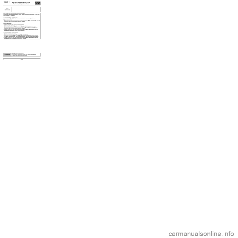
DF093
CONTINUED
Check that the wheel speed sensor mounting is in good condition.
Visually inspect the condition of the target (for clogging, metallic contamination, bearing grease, etc.) and clean
using compressed air if necessary.
For versions equipped with disc brakes:
Check the sensor/target air gap through one wheel revolution (0.1 < rear wheel air gap < 0.9 mm).
If the air gap is incorrect:
–Replace the instrumented bearing/wheel sensor mounting assembly (see MR 411, Mechanical, 33A, Rear axle
components, Rear hub carrier bearing: Removal - Refitting).
If the air gap is correct.
–Swap both rear wheel brake discs as well as the brake pads.
–Clear the computer fault memory.
–Carry out a road test followed by another check with the diagnostic tool.
–If the fault initially declared as DF093 has become DF092 Rear right-hand wheel target, replace
the instrumented bearing/wheel sensor mounting assembly (see MR 411 Mechanical, 33A, Rear axle
components, Rear hub carrier bearing: Removal - Refitting).
–If the fault remains on the same side, replace component 151 (see MR 411, Mechanical, 38C, Anti-lock
braking system, Wheel speed sensor, Removal - Refitting).
For versions equipped with drum brakes:
–Swap both rear wheel brake drums.
–Clear the computer fault memory.
–Carry out a road test followed by another check with the diagnostic tool.
–If the initially declared fault DF093 became DF092 "Rear right-hand wheel target " , replace the target
(see MR 411 Mechanical system, 33A, Rear axle components, Rear brake drums, removal-refitting).
–If the fault remains on the same side, replace component 151 (see MR 411, Mechanical, 38C, Anti-lock
braking system, Rear wheel speed sensor, Removal - Refitting).
Page 58 of 101
38C-58
AFTER REPAIRClear the computer fault memory.
Carry out a road test followed by another check with the diagnostic tool
If the fault is still present, contact the Techline.
V3 MR-413-X44-38C050$102.mif
38C
Bosch 8.1 ESP
Vdiag No.: 05
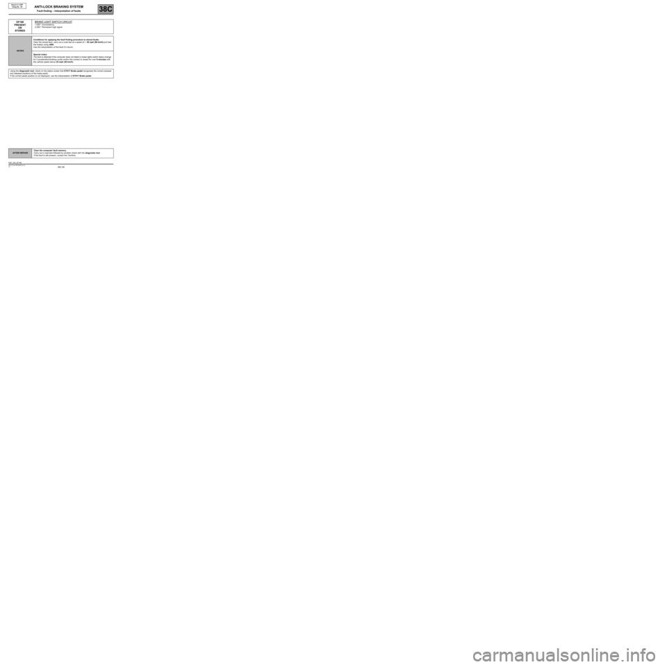
DF188
PRESENT
OR
STOREDBRAKE LIGHT SWITCH CIRCUIT
1.DEF: Inconsistency
2.DEF: Permanent high signal
NOTESConditions for applying the fault finding procedure to stored faults:
Clear the stored fault, carry out a road test at a speed of > 36 mph (60 km/h) and test
the brakes using ABS.
Use the interpretation of the fault if it recurs.
Special notes:
The fault is detected if the computer does not detect a brake lights switch status change
for 4 acceleration/braking cycles and/or the contact is closed for over 6 minutes with
the vehicle speed above 24 mph (40 km/h).
Using the diagnostic tool, check on the status screen that ET017 Brake pedal recognises the correct pressed
and released positions of the brake pedal.
If the correct pedal position is not displayed, use the interpretation of ET017 Brake pedal.
ANTI-LOCK BRAKING SYSTEM
Fault finding – Interpretation of faults
ESP_V05_DF188
Page 89 of 101
38C-89
AFTER REPAIRClear the computer fault memory.
Carry out a road test followed by another check with the diagnostic tool.
V3 MR-413-X44-38C050$180.mif
ANTI-LOCK BRAKING SYSTEM
Fault finding – Fault finding chart38C
Bosch 8.1 ESP
Vdiag No.: 05
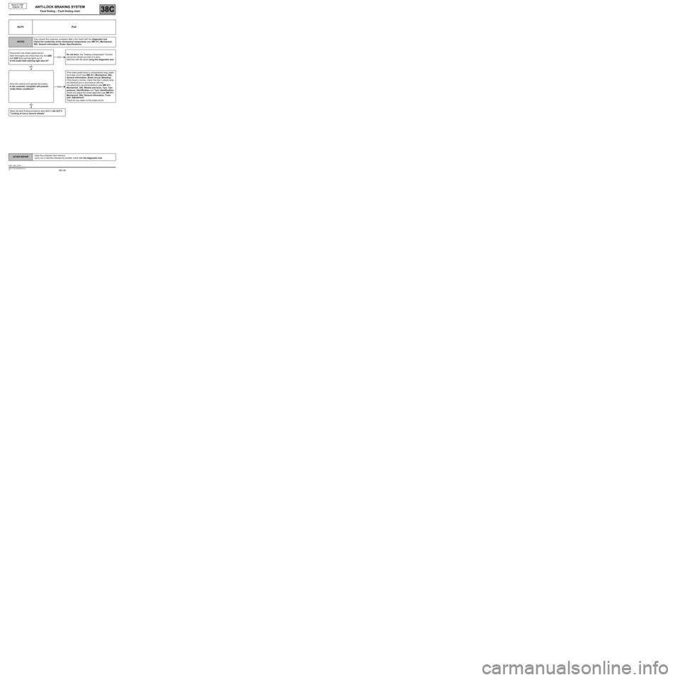
ALP3 Pull
NOTESOnly consult this customer complaint after a full check with the diagnostic tool.
Check the conformity of the mechanical components (see MR 411, Mechanical,
30A, General information, Brake, Specifications).
Disconnect one wheel speed sensor.
Start the engine and check that only the ABS
and ESP fault warning lights are lit.
Is the brake fault warning light also lit?Do not drive, the "braking compensator" function
cannot be carried out (risk of a spin).
Deal first with the faults using the diagnostic tool.
Drive the vehicle and operate the brakes.
Is the customer complaint still present
under these conditions?If the brake pedal travel is comparatively long, bleed
the brake circuit (see MR 411, Mechanical, 30A,
General information, Brake circuit, Bleeding).
If the travel is normal, check that the 4 vehicle tyres
are identical and in accordance with the
manufacturer's recommendations (see MR 411,
Mechanical, 35A, Wheels and tyres, Tyre, Tyre
pressure, Identification and Tyre, Identification).
Check and adjust the wheel alignment (see MR 411,
Mechanical, 30A, General information, Front
axle, Adjustment).
Check for any leaks on the brake circuit.
Apply the fault finding procedure described in the ALP 2
"Locking of one or several wheels".
YES
NO
YES
NO
ESP_V05_ALP3
Page 90 of 101
38C-90
AFTER REPAIRClear the computer fault memory.
Carry out a road test followed by another check with the diagnostic tool.
V3 MR-413-X44-38C050$180.mif
ANTI-LOCK BRAKING SYSTEM
Fault finding – Fault finding chart38C
Bosch 8.1 ESP
Vdiag No.: 05
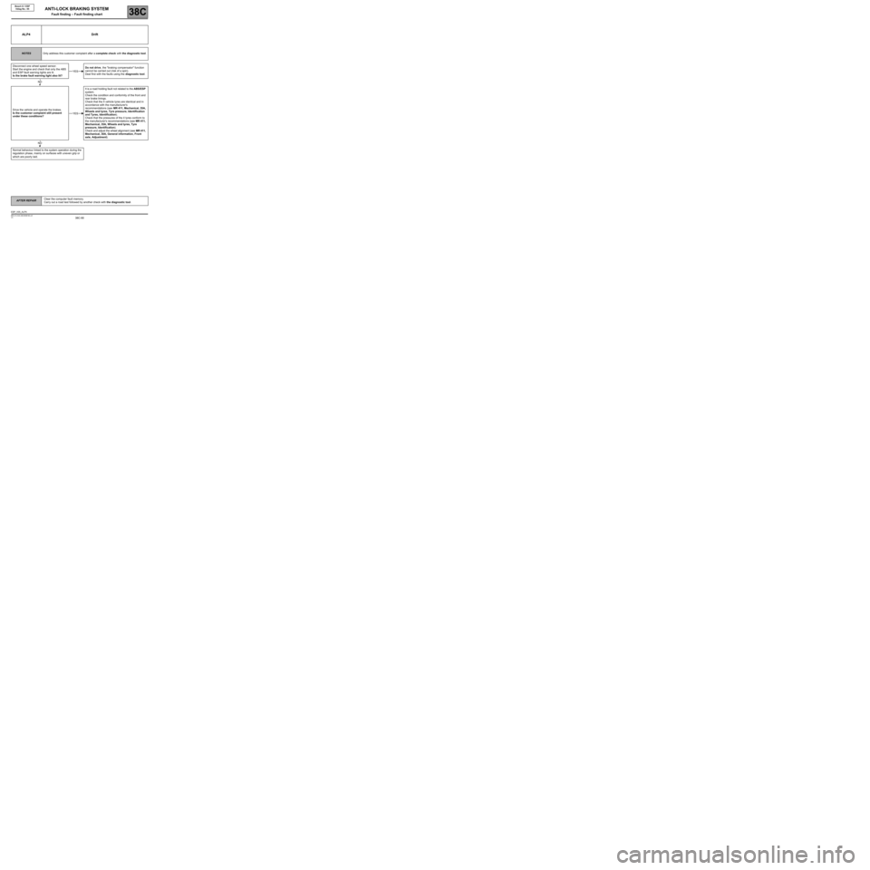
ALP4 Drift
NOTESOnly address this customer complaint after a complete check with the diagnostic tool.
Disconnect one wheel speed sensor.
Start the engine and check that only the ABS
and ESP fault warning lights are lit.
Is the brake fault warning light also lit?Do not drive, the "braking compensator" function
cannot be carried out (risk of a spin).
Deal first with the faults using the diagnostic tool.
Drive the vehicle and operate the brakes.
Is the customer complaint still present
under these conditions?It is a road holding fault not related to the ABS/ESP
system.
Check the condition and conformity of the front and
rear brake linings.
Check that the 4 vehicle tyres are identical and in
accordance with the manufacturer's
recommendations (see MR 411, Mechanical, 35A,
Wheels and tyres, Tyre pressure, Identification
and Tyres, Identification).
Check that the pressures of the 4 tyres conform to
the manufacturer's recommendations (see MR 411,
Mechanical, 35A, Wheels and tyres, Tyre
pressure, Identification).
Check and adjust the wheel alignment (see MR 411,
Mechanical, 30A, General information, Front
axle, Adjustment).
Normal behaviour linked to the system operation during the
regulation phase, mainly on surfaces with uneven grip or
which are poorly laid.
YES
NO
YES
NO
ESP_V05_ALP4