ignition RENAULT TWINGO 2009 2.G Chasiss ESP Workshop Manual
[x] Cancel search | Manufacturer: RENAULT, Model Year: 2009, Model line: TWINGO, Model: RENAULT TWINGO 2009 2.GPages: 101
Page 2 of 101
38C -2V3 MR-413-X44-38C050$010.mif
38C
Bosch 8.1 ESP
Vdiag No.: 05
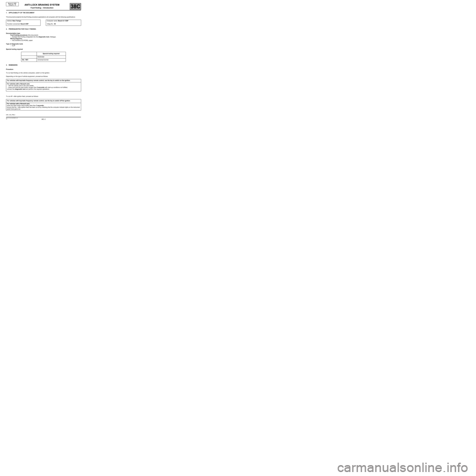
1. APPLICABILITY OF THE DOCUMENT
Th is d ocument p resents the fault finding procedure applica ble to all computers with the following specifications:
2. PREREQUISITES FOR FAULT FINDING:
Documentation type
Fault finding procedures (this document):
–Assisted fault finding (integrated into the diagnostic tool), Dialogys.
Wiring Diagrams:
–Visu-Schéma (CD-ROM), paper.
Type of diagnostic tools
–CLIP
Special tooling required
3. REMINDERS
Procedure
To run fault finding on the vehicle computers, switch on the ignition.
Depending on the type of vehicle equipment, proceed as follows:
To cut off + after ignition feed, proceed as follows:Vehicle: New TwingoComputer name: Bosch 8.1 ESP
Function concerned: Bosch ESPVdiag No.: 05
Special tooling required
Multimeter
Elé. 1681Universal bornier
For vehicles with key/radio frequency remote control, use the key to switch on the ignition.
For vehicles with a Renault card,
–with the vehicle card in the card reader,
–press and hold the start button (longer than 5 seconds) with start-up conditions not fulfilled,
connect the diagnostic tool and perform the required operations.
For vehicles with key/radio frequency remote control, use the key to switch off the ignition.
For vehicles with a Renault card,
press the Start button twice briefly (less than 3 seconds),
ensure that the + after ignition feed has been cut off by checking that the computer indicator lights on the instrument
panel have gone out.
ESP_V05_PRELI
ANTI-LOCK BRAKING SYSTEM
Fault finding – Introduction
Page 3 of 101
38C -3V3 MR-413-X44-38C050$010.mif
ANTI-LOCK BRAKING SYSTEM
Fault finding – Introduction
Bosch 8.1 ESP
Vdiag No.: 05
38C
Faults
Faults are declared present or stored (depending on whether they appeared in a certain context and have
disappeared since, or whether they remain present but are not diagnosed within the current context).
The present or stored status of faults should be taken into consideration when the diagnostic tool is used after the
+ after ignition feed (without activating the system components).
For a present fault, apply the procedure described in the Interpretation of faults section.
For a stored fault, note the faults displayed and apply the Notes section.
If the fault is confirmed when the instructions in the Notes section are applied, the fault is present. Deal with the
fault.
If the fault is not confirmed, check:
the electrical connections that correspond to the fault,
the connectors for this connection,
the resistance of the faulty component,
the condition of the wires.
Refer to paragraphs 4.1 Checking wiring and 4.2 Checking connectors
Conformity check
The aim of the conformity check is to check data which does not produce a fault on the diagnostic tool when the
data is inconsistent. Therefore, this stage is used to:
carry out fault finding on faults that do not have a fault display, and which may correspond to a customer complaint.
check that the system is operating correctly and that there is no risk of a fault recurring after repair.
This section gives the fault finding procedures for statuses and parameters and the conditions for checking them.
If a status is not behaving normally or a parameter is outside permitted tolerance values, you should consult the
corresponding fault finding page.
Customer complaints - Fault finding chart
If the test with the diagnostic tool is OK but the customer complaint is still present, the fault should be dealt with by
customer complaints.
Asummary oftheoverall proc edure to follow isprovidedonthe fol lowing page in the form of a flow chart.
Page 15 of 101

38C-15V3 MR-413-X44-38C050$070.mif
38C
Bosch 8.1 ESP
Vdiag No.: 05
REPLACING THE COMPUTER:
When replacing the computer (see MR 411, Mechanical, 38C, Anti-lock braking system, Braking computer:
Removal - Refitting), use the following procedure:
–Switch off the ignition.
–Replace the computer.
–Enter the VIN number using command VP001 Enter VIN (see Configurations and Programming).
–Configure the tachometric index using command VP007 Tachometric index (see Configurations and
programming).
–Configure the vehicle parameters using command VP004 Vehicle parameters (see Configurations and
programming).
–Inhibit or authorise illumination of the automatic brake lights (depending on the country's legislation) using
command VP021 Inhibit automatic brake lights or VP022 Authorise automatic brake lights.
–Clear the ESP sensor offsets using command RZ011 Sensors offsets (see Configurations and programming).
–Enter the After-Sales date using command VP006 Enter last APV* operation date.
–Perform a road test followed by a fault reading to confirm that the system is operating correctly.
REPLACING THE STEERING WHEEL ANGLE SENSOR:
–Calibrate the steering wheel angle sensor using command VP003 Steering wheel angle sensor (see
Configurations and programming).
–Clear the ESP sensor offsets using command RZ011 Sensor offsets.
REPLACING THE COMBINED SENSOR:
–Clear the ESP sensor offsets using command RZ011 Sensor offsets.
* APV: After-Sales
ANTI-LOCK BRAKING SYSTEM
Fault finding – Replacement of components
Page 16 of 101

38C-16V3 MR-413-X44-38C050$080.mif
38C
Bosch 8.1 ESP
Vdiag No.: 05
Parameters:
VP001: Enter VIN
This command allows the vehicle identification number to be entered into the computer.
Use this command each time the computer is replaced. The VIN (VF...) is engraved on the manufacturer's plate on
the front right-hand door pillar and stamped on the body under the windscreen on the left-hand side.
VP003: Steering wheel angle sensor
This command is used to calibrate the steering wheel angle.
With the steering wheel horizontal and the front wheels set straight ahead, calibrate the steering wheel angle sensor
using command VP003 on the diagnostic tool.
VP004: Vehicle parameters
This command configures the engine type configuration, the braking definition and the body type. Select the
command VP004 on the diagnostic tool.
VP006: Enter last After-Sales operation date
Whenever the ABS system is worked on in the shop, the date must be entered.
Select command VP006 on the diagnostic tool.
Enter the service date using the diagnostic tool keypad.
VP007: Tachometric index
This command is used to program the computer memory with the index required to calculate the vehicle speed
according to the tyre size.
The BOSCH 8.1 ESP computer supplies the vehicle speed signal to all areas where this information is needed
(instrument panel, engine management, etc.). This vehicle speed signal replaces the one supplied by the speed
sensor located on the gearbox.
The ESP computer calculates the vehicle speed from the wheel speed and the tyre circumference.
The tyre circumference must be programmed into the memory of a new computer. This consists of entering an index
"X" using the command VP007 "Tachometric index" on the diagnostic tool.
Once the number has been entered using the VP007 command, delete the fault in the computer memory and then
switch off the ignition. Use parameter PR030 "Tachometric index" to check that the index entered has been
recognised by the system.
VP021: Inhibit automatic brake lights
This command deactivates the automatic brake lights.
Select command VP021 on the diagnostic tool.
VP022: Automatic brake lights authorisation
This command authorises the automatic brake lights.
Select command VP022 on the diagnostic tool.
* APV: After-SalesNote:
The vehicle speed is supplied by a wire (connection 47F) to the radio, to the electric power-assisted
steering, to the electric sunroof and by the multiplex network for the other computers.
ANTI-LOCK BRAKING SYSTEM
Fault finding – Configurations and programming
Page 21 of 101
38C-21
AFTER REPAIRClear the computer fault memory.
Carry out a road test followed by another check with the diagnostic tool
If the fault is still present, contact the Techline.
V3 MR-413-X44-38C050$101.mif
ANTI-LOCK BRAKING SYSTEM
Fault finding – Interpretation of faults38C
Bosch 8.1 ESP
Vdiag No.: 05
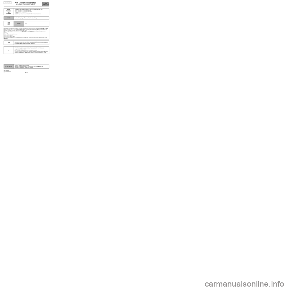
DF006
PRESENT
OR
STOREDFRONT LEFT-HAND WHEEL SPEED SENSOR CIRCUITCO.0: open circuit or short circuit to earth
CO.1: open circuit or short circuit to +12 V
1. DEF: internal electronic fault
2. DEF: magnetic or mechanical fault on the target or interference
NOTESUse the Wiring Diagram Technical Note for New Twingo.
CO.0
CO.1
1.DEF
NOTESNone.
Check the connection and condition (possible wiring damage) of the connectors of components 1094 and 153.
If the connector is faulty (see Technical Note 6015A, Repairing electrical wiring, Wiring: Precautions for
repair), repair the connector, otherwise replace the wiring.
Swap the 2 front wheel speed sensors (see MR 411 Mechanical, 38C, Wheel speed sensor, Removal -
Refitting).
Clear the computer fault memory.
Switch off the ignition.
Switch on the ignition again.
Did the fault initially declared as DF006 become fault DF026 "Front right-hand wheel speed sensor circuit"
present?
YESReplace component 153 (see MR 411 Mechanical, 38C, Anti-lock braking system,
Front wheel speed sensor, Removal - Refitting).
NOCheck the insulation and continuity of connections 4C and 4E between
components 153 and 1094.
Also check the insulation between these 2 connections.
If the connection(s) are faulty (see Technical Note 6015A, Electrical wiring repair,
Wiring: Precautions for repair), repair the wiring, otherwise replace the wiring.
ESP_V05_DF006
Page 22 of 101

38C-22
AFTER REPAIRClear the computer fault memory.
Carry out a road test followed by another check with the diagnostic tool
If the fault is still present, contact the Techline.
V3 MR-413-X44-38C050$101.mif
ANTI-LOCK BRAKING SYSTEM
Fault finding – Interpretation of faults38C
Bosch 8.1 ESP
Vdiag No.: 05
DF006
CONTINUED 1
2.DEFNOTESConditions for applying the fault finding procedure to
stored faults:
The fault is declared present after a road test.
Check the connection and condition (possible wiring damage) of the connectors of components 1094 and 153.
If the connector is faulty (see Technical Note 6015A, Repairing electrical wiring, Wiring: Precautions for
repair), repair the connector, otherwise replace the wiring.
Swap the 2 front wheel speed sensors (see MR 411 Mechanical, 38C, Anti-lock braking system, Wheel speed
sensor: Removal - Refitting).
Clear the computer fault memory.
Switch off the ignition.
Switch on the ignition again.
Carry out a road test.
Did the fault initially declared as DF006 become fault DF026 "Front right-hand wheel speed sensor circuit"
present?
Page 29 of 101

38C-29
AFTER REPAIRClear the computer fault memory.
Carry out a road test followed by another check with the diagnostic tool
If the fault is still present, contact the Techline.
V3 MR-413-X44-38C050$101.mif
ANTI-LOCK BRAKING SYSTEM
Fault finding – Interpretation of faults38C
Bosch 8.1 ESP
Vdiag No.: 05
DF020
PRESENTTACHOMETRIC INDEX PROGRAMMING1. DEF: tachometric index not programmed
NOTESNone.
The ESP computer with the tachometric function supplies the vehicle speed signal to all areas where this
information is needed (instrument panel, engine management, etc.).
This vehicle speed signal replaces the one supplied by the speed sensor located on the gearbox.
The ESP computer calculates the vehicle speed from the wheel speed and the tyre circumference.
The tyre circumference must be programmed into the memory of a new computer. This consists
of entering an X index using command VP007 Tachometric index on the diagnostic tool.
Once the index has been entered using command VP007 Tachometric index, clear the computer fault memory
and then switch off the ignition.
Use parameter PR030 Tachometric index to check that the index entered is being used correctly by the system.
ESP_V05_DF020
Page 30 of 101
38C-30
AFTER REPAIRClear the computer fault memory.
Carry out a road test followed by another check with the diagnostic tool
If the fault is still present, contact the Techline.
V3 MR-413-X44-38C050$101.mif
ANTI-LOCK BRAKING SYSTEM
Fault finding – Interpretation of faults38C
Bosch 8.1 ESP
Vdiag No.: 05
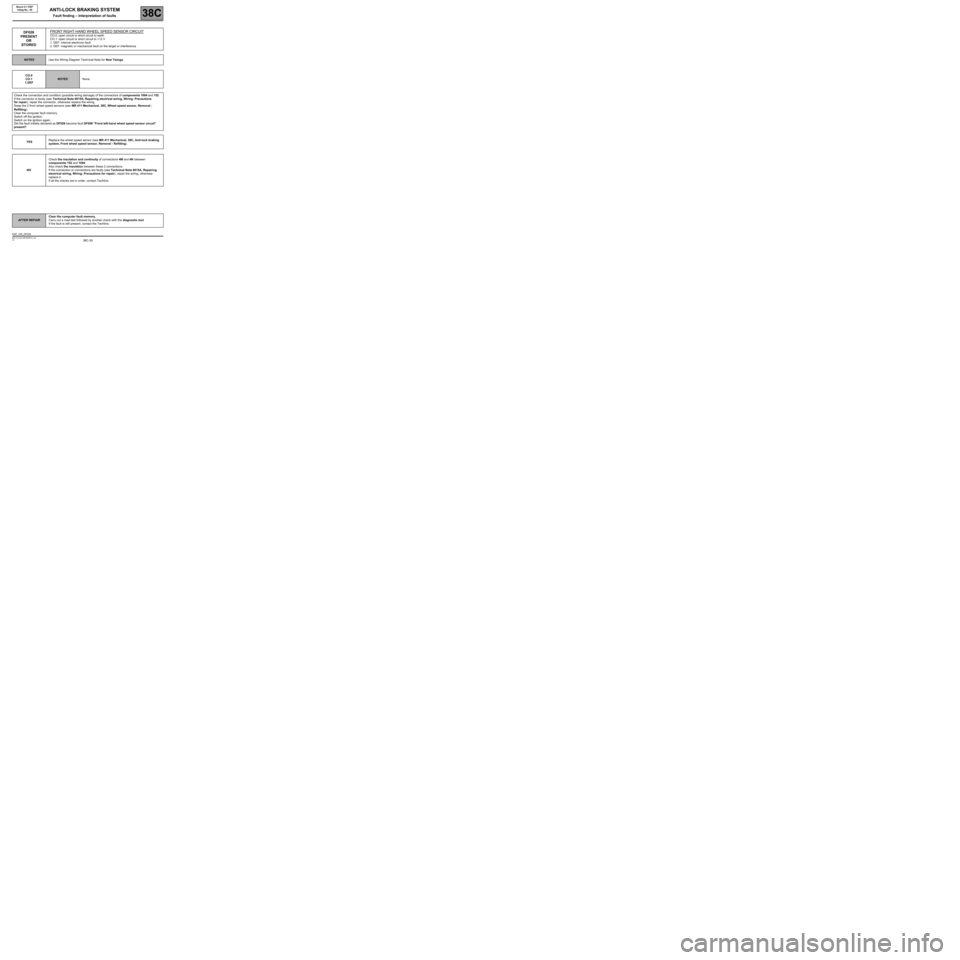
DF026
PRESENT
OR
STOREDFRONT RIGHT-HAND WHEEL SPEED SENSOR CIRCUITCO.0: open circuit or short circuit to earth
CO.1: open circuit or short circuit to +12 V
1. DEF: internal electronic fault
2. DEF: magnetic or mechanical fault on the target or interference
NOTESUse the Wiring Diagram Technical Note for New Twingo.
CO.0
CO.1
1.DEF
NOTESNone.
Check the connection and condition (possible wiring damage) of the connectors of components 1094 and 152.
If the connector is faulty (see Technical Note 6015A, Repairing electrical wiring, Wiring: Precautions
for repair), repair the connector, otherwise replace the wiring.
Swap the 2 front wheel speed sensors (see MR 411 Mechanical, 38C, Wheel speed sensor, Removal -
Refitting).
Clear the computer fault memory.
Switch off the ignition.
Switch on the ignition again.
Did the fault initially declared as DF026 become fault DF006 "Front left-hand wheel speed sensor circuit"
present?
YESReplace the wheel speed sensor (see MR 411 Mechanical, 38C, Anti-lock braking
system, Front wheel speed sensor, Removal - Refitting).
NOCheck the insulation and continuity of connections 4M and 4N between
components 152 and 1094.
Also check the insulation between these 2 connections.
If the connection or connections are faulty (see Technical Note 6015A, Repairing
electrical wiring, Wiring: Precautions for repair), repair the wiring, otherwise
replace it.
If all the checks are in order, contact Techline.
ESP_V05_DF026
Page 31 of 101
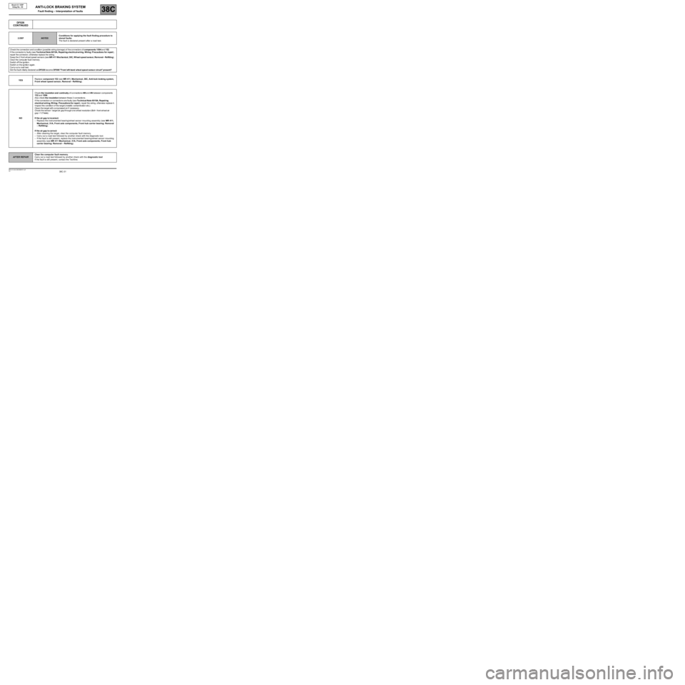
38C-31
AFTER REPAIRClear the computer fault memory.
Carry out a road test followed by another check with the diagnostic tool
If the fault is still present, contact the Techline.
V3 MR-413-X44-38C050$101.mif
ANTI-LOCK BRAKING SYSTEM
Fault finding – Interpretation of faults38C
Bosch 8.1 ESP
Vdiag No.: 05
DF026
CONTINUED
2.DEFNOTESConditions for applying the fault finding procedure to
stored faults:
The fault is declared present after a road test.
Check the connection and condition (possible wiring damage) of the connectors ofcomponents 1 094and152.
Iftheconnector is faulty (seeTe chnical Note 6015A, Repairing e lectrical wiring, Wiring: Precautions for repair),
repair the connector, otherwise replace the wiring.
Swap the 2 front wheel speed sensors (seeMR 411 M echanical, 38C, W heel speed sensor, Removal - Refitting).
Clearthecomputer fault memory.
Switch offtheignition.
Switch on the ignit io nagain.
Carry out a road test.
Did the fault i nitially declared asDF0 26becomeDF006 "Front left-hand wheel speed sensor circuit" present?
YESReplace component 152 (see MR 411, Mechanical, 38C, Anti-lock braking system,
Front wheel speed sensor, Removal - Refitting).
NOCh eckthe insulatio n a nd c on t i n ui t yof connections4Mand4Nbetween components
152and1094.
Alsocheckthe insulationbetween these 2 connections.
Iftheconnection or connections are faulty (seeTe chnical Note 6 015A, Repairing
electrical wiring, W iring: Precautions for repair), repair the wiring, otherwise replace it.
Inspect the condition of the target (metallic contamination etc.).
Cle an the target with compressed air if necessary.
Ch eck the sensor / target air gap through one wheel revolution (0.4
If the air gap isincorrect:
–Replace the instrumented bearing/wheel sensor mounting assembly (see MR 411,
Mechanical, 31A, Front axle components, Front hub carrier bearing: Removal
– Refitting).
If the air gap iscorrect:
–After cleaning the target, clear the computer fault memory.
–Carry out a road test followed by another check with the diagnostic tool.
–If the fault is still present, replace the instrumented bearing/wheel sensor mounting
assembly (see MR 411 Mechanical, 31A, Front axle components, Front hub
carrier bearing: Removal – Refitting).
Page 34 of 101

38C-34
AFTER REPAIRClear the computer fault memory.
Carry out a road test followed by another check with the diagnostic tool
If the fault is still present, contact the Techline.
V3 MR-413-X44-38C050$101.mif
ANTI-LOCK BRAKING SYSTEM
Fault finding – Interpretation of faults38C
Bosch 8.1 ESP
Vdiag No.: 05
DF055
PRESENTVEHICLE PARAMETER PROGRAMMINGDEF: configuration absent or incorrect
NOTESNone.
Configure the vehicle parameters using command VP004 Vehicle parameters (see help table in clip).
Clear the fault memory, and initialise the computer (switch the + after ignition feed off and on again).
Check for any possible faults.
ESP_V05_DF055