wheel RENAULT TWINGO 2009 2.G Chasiss Workshop Manual
[x] Cancel search | Manufacturer: RENAULT, Model Year: 2009, Model line: TWINGO, Model: RENAULT TWINGO 2009 2.GPages: 281
Page 254 of 281
37A-75
MECHANICAL COMPONENT CONTROLS
Parking brake cables: Removal - Refitting
EQ UIPMENT LEVEL EA0 or EQUIPMENT LEVEL EA1 or EQUIPMENT LEVEL EA3 or EQUIPMENT LEVEL EA5
or EQUIPMENT LEVEL EAG or EQUIPMENT LEVEL EZ2 or EQUIPMENT LEVEL EZ4
37A
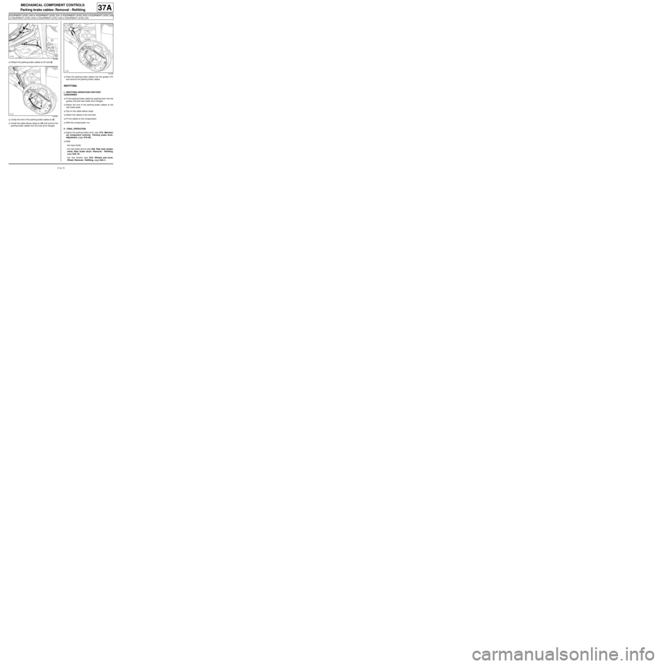
aDetach the parking brake cables at (7) and (8) .
aUnclip the end of the parking brake cables at (9) .
aUnclip the cable sleeve stops at (10) and remove the
parking brake cables from the rear drum flanges.aPass the parking brake cables into the guides (11)
and remove the parking brake cables.
REFITTING
I - REFITTING OPERATION FOR PART
CONCERNED
aFit the parking brake cables by passing them into the
guides (11) and rear brake drum flanges.
aAttach the end of the parking brake cables to the
rear brake pads.
aClip on the cable sleeve stops.
aAttach the cables to the fuel tank.
aFit the cables to the compensator.
aRefit the compensator nut.
II - FINAL OPERATION.
aAdjust the parking brake lever (see 37A, Mechani-
cal component controls, Parking brake lever:
Adjustment, page 37A-48) .
aRefit:
-the heat shield,
-the rear brake drums (see 33A, Rear axle compo-
nents, Rear brake drum: Removal - Refitting,
page 33A-19) ,
-the rear wheels (see 35A, Wheels and tyres,
Wheel: Removal - Refitting, page 35A-1) .
121329
121331
121330
Page 255 of 281
37A-76
MECHANICAL COMPONENT CONTROLS
Parking brake cables: Removal - Refitting
EQ UIPMENT LEVEL SPORT
37A
REMOVAL
I - REMOVAL PREPARATION OPERATION
aFit:
-the vehicle on a two-post lift (see Vehicle: Towing
and lifting) (02A, Lifting equipment),
-the parking brake lever in the released position.
aRemove the rear wheels (see 35A, Wheels and ty-
res, Wheel: Removal - Refitting, page 35A-1) .
aRemove:
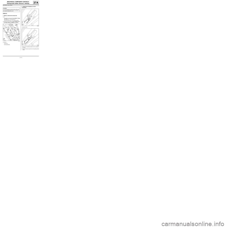
-the clips (1) ,
-the heat shield (2) .II - OPERATION FOR REMOVAL OF PART
CONCERNED
aLoosen nut (3) .
aRemove the handbrake cables from the compensa-
tor at (4) .
aUnclip the sleeve stops (5) from the parking brake
cables. WARNING
To avoid damaging the parking brake cable protec-
tors and causing premature wear of the system, do
not handle the cables with a tool.
121326
121334
121334
Page 256 of 281
37A-77
MECHANICAL COMPONENT CONTROLS
Parking brake cables: Removal - Refitting
EQ UIPMENT LEVEL SPORT
37A
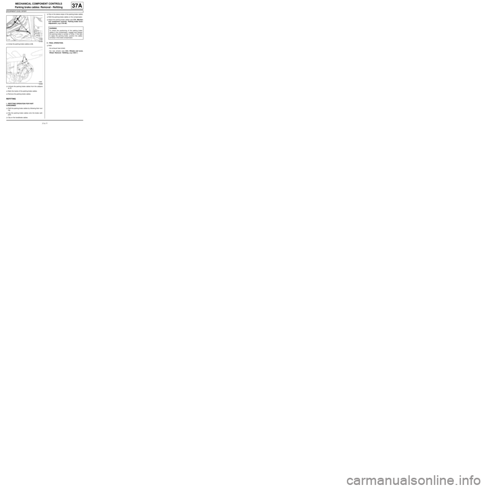
aUnclip the parking brake cables at (6) .
aUnhook the parking brake cables from the callipers
at (7) .
aMark the tracks of the parking brake cables.
aRemove the parking brake cables.
REFITTING
I - REFITTING OPERATION FOR PART
CONCERNED
aRefit the parking brake cables by following their rout-
ing.
aClip the parking brake cables onto the brake calli-
pers.
aClip on the handbrake cables.aClip on the sleeve stops of the parking brake cables.
aRefit the parking brake cables on the compensator.
aAdjust the parking brake cables (see 37A, Mechan-
ical component controls, Parking brake lever:
Adjustment, page 37A-48) .
II - FINAL OPERATION.
aRefit:
-the exhaust heat shield,
-the rear wheels (see 35A, Wheels and tyres,
Wheel: Removal - Refitting, page 35A-1) .
121329
132468
WARNING
To check the positioning of the parking brake
cables in the compensator, engage and release
the par king brake a number of times. If this fails
to apply the par king brake, position the cables
correctly in the brake compensator.
Page 257 of 281
37A-78
MECHANICAL COMPONENT CONTROLS
Brake servo: Check
RIGHT-HAND DRIVE
37A
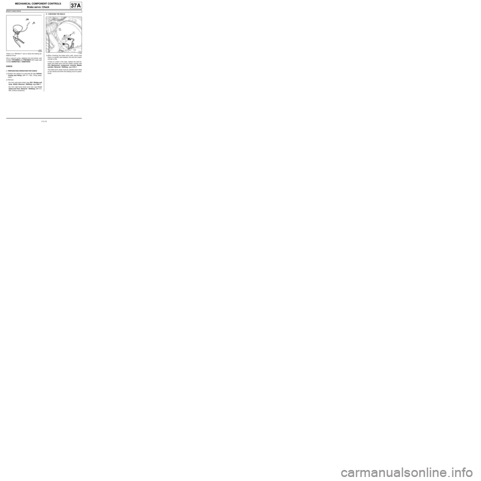
There is no “RENAULT” tool to check the braking as-
sistance circuit.
Use a vacuum pump, adapting the end pieces, part
number 7701349942 and 7700105874 with a pipe, part
number 8200027352 or 8200376245.
CHECK
I - PREPARATION OPERATION FOR CHECK
aPosition the vehicle on a two-post lift (see Vehicle:
Towing and lifting) (MR 411, 02A, Lifting equip-
ment).
aRemove:
-the front right-hand wheel (see 35A, Wheels and
tyres, Wheel: Removal - Refitting, page 35A-1) ,
-the front right-hand wheel arch liner (see Front
wheel arch liner: Removal - Refitting) (MR 412,
55A, Exterior protection).II - CHECKING THE SEALS
aWhen checking the brake servo seal, ensure that
there is a perfect seal between this and the master
cylinder at (A) .
If there is a leak in this area, replace the seal be-
tween the brake servo and the master cylinder (see
37A, Mechanical component controls, Master
cylinder: Removal - Refitting, page 37A-1) .
The brake servo seals must be checked when fitted
on the vehicle and when the braking circuit is opera-
tional.
122228
117948
Page 259 of 281
37A-80
MECHANICAL COMPONENT CONTROLS
Brake servo: Check
RIGHT-HAND DRIVE
37A
aConnect a vacuum pump to the end of the non-re-
turn valve.
aActivate the vacuum pump to obtain a vacuum of
500 mbar.
aCheck that the vacuum pressure does not drop. If it
does, the non-return valve is pierced; replace the
valve (see 37A, Mechanical component controls,
Brake servo non-return valve: Removal - Refit-
ting, page 37A-11) .
aRefit the non-return valve pipe on the intake distribu-
tor.V - CHECKING THE VACUUM PUMP
aConnect the external vacuum pump to the engine
vacuum pump.
aStart the engine.
aCheck the following values:
-550 mbar in 5 seconds for an engine speed of 700
rpm,
-700 mbar in 3 seconds and 900 mbar in 5 sec-
onds for an engine speed of 4050 rpm.
aReplace the vacuum pump if the values are different
(see 37A, Mechanical component controls, Vacu-
um pump: Removal - Refitting, page 37A-25) .
aRefit the non-return valve pipe onto the vacuum
pump.
VI - FINAL OPERATION.
aRefit:
-the front right-hand wheel arch liner (see Front
wheel arch liner: Removal - Refitting) (MR 412,
55A, Exterior protection),
-the front right-hand wheel (see 35A, Wheels and
tyres, Wheel: Removal - Refitting, page 35A-1) .
123907
D4F or D7F
K9K
106889
Page 260 of 281
38C-1
ANTI-LOCK BRAKING SYSTEM
Hydraulic brake unit: List and location of components38C
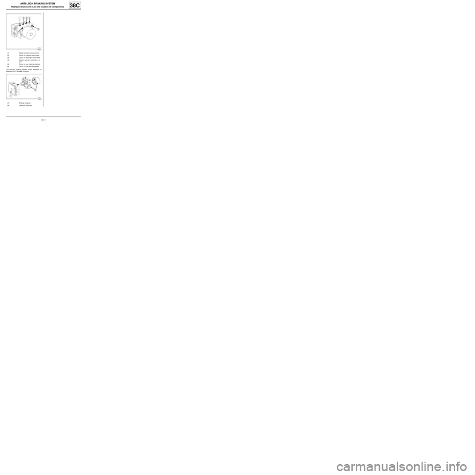
The anti-lock braking system pump assembly is
equipped with a 26-track computer.
102311
(1) Master cylinder pr imar y circuit
(2) Circuit for front left-hand wheel
(3) Circuit for front right-hand wheel
(4) Master cylinder secondary cir-
cuit
(5) Circuit for rear right-hand wheel
(6) Circuit for rear left-hand wheel
19113
(7) Braking computer
(8) Hydraulic assembly
Page 261 of 281
38C-2
ANTI-LOCK BRAKING SYSTEM
Hydraulic brake unit: Removal - Refitting
K9K, and LEFT-HAND DRIVE
38C
REMOVAL
I - REMOVAL PREPARATION OPERATION
aPosition the vehicle on a two-post lift (see Vehicle:
Towing and lifting) (MR 411, 02A, Lifting equip-
ment).
aDisconnect the battery (see Battery: Removal - Re-
fitting) (MR 411, 80A, Battery).
aPosition the pedal press on the brake pedal to limit
the outflow of brake fluid.
aRemove:
-the front wheel on the passenger side (see 35A,
Wheels and tyres, Wheel: Removal - Refitting,
page 35A-1) ,
-the front wheel arch liner, on the passenger side
(see Front wheel arch liner: Removal - Refitting)
(MR 412, 55A, Exterior protection),
-the scuttle panel grille (see Scuttle panel grille:
Removal - Refitting) (MR 412, 56A, Exterior
equipment),
-the scoop under the scuttle panel grille (see Scoop
under the scuttle panel grille: Removal - Refit-
ting) (MR 412, 56A, Exterior equipment),
-the air filter box (see Air filter unit: Removal - Re-
fitting) (MR 411, 12A, Fuel mixture).aRemove:
-the bolts (1) from the lifting eye on the right-hand
side,
-the lifting eye on the right-hand side (2) ,
-the rigid pipe (3) from the EGR circuit.
aRemove the clip (4) from the soundproofing.
aMove the soundproofing aside (5) to access the hy-
draulic unit. Equipment required
pedal press
Tightening torquesm
hydraulic unit bolts on
its inter mediate bracket8 Nm
hydraulic unit inter medi-
ate bracket bolts on the
main hydraulic unit
mounting6.5 Nm
hydraulic unit main
mounting bolts on the
body8 Nm
rigid brake pipe unions
on the hydraulic unit13 Nm
112329
121358
Page 263 of 281
38C-4
ANTI-LOCK BRAKING SYSTEM
Hydraulic brake unit: Removal - Refitting
K9K, and LEFT-HAND DRIVE
38C
aRemove:
-the hydraulic assembly intermediate bracket bolts
(10) ,
-the « hydraulic unit intermediate bracket - hydraulic
unit » assembly (11) from the main mounting,
-the hydraulic unit bolts (12) from its intermediate
bracket,
-the hydraulic unit from its intermediate bracket.
REFITTING
I - REFITTING OPERATION FOR PART
CONCERNED
aRefit:
-the hydraulic unit onto its intermediate bracket,
-the hydraulic unit bolts onto its intermediate brack-
et.
aTorque tighten the hydraulic unit bolts on its inter-
mediate bracket (8 Nm).
aRefit:
-the « hydraulic unit intermediate bracket - hydraulic
unit » assembly onto the main mounting,
-the hydraulic unit intermediate bracket bolts onto
the main hydraulic unit mounting.
aTorque tighten the hydraulic unit intermediate
bracket bolts on the main hydraulic unit mount-
ing (6.5 Nm).aRefit:
-the « hydraulic unit mounting - hydraulic unit » as-
sembly on the body,
-the hydraulic unit main mounting bolts on the body.
aTorque tighten the hydraulic unit main mounting
bolts on the body (8 Nm).
II - FINAL OPERATION.
aRemove the blanking plugs.
aFit and tighten the rigid brake pipe unions on the hy-
draulic unit.
aTorque tighten the rigid brake pipe unions on the
hydraulic unit (13 Nm).
aConnect the computer connector on the hydraulic
unit.
aFit the bulkhead soundproofing.
aRefit:
-the soundproofing clip,
-the rigid exhaust gas recirculation circuit pipe,
-the lifting eye on the right-hand side,
-the air filter box (see Air filter unit: Removal - Re-
fitting) (MR 411, 12A, Fuel mixture),
-the scoop under the scuttle panel grille (see Scoop
under the scuttle panel grille: Removal - Refit-
ting) (MR 412, 56A, Exterior equipment),
-the scuttle panel grille (see Scuttle panel grille:
Removal - Refitting) (MR 412, 56A, Exterior
equipment),
-the front wheel arch liner, on the passenger side
(see Front wheel arch liner: Removal - Refitting)
(MR 412, 55A, Exterior protection),
-the front wheel on the passenger side (see 35A,
Wheels and tyres, Wheel: Removal - Refitting,
page 35A-1) .
aRemove the pedal press from the brake pedal.
aConnect the battery (see Battery: Removal - Refit-
ting) (MR 411, 80A, Battery).
aBleed the braking circuit (see 30A, General infor-
mation, Braking circuit: Bleed, page 30A-4) .
121456
Page 264 of 281
38C-5
ANTI-LOCK BRAKING SYSTEM
Hydraulic brake unit: Removal - Refitting
D4F or D7F, and LEFT-HAND DRIVE
38C
REMOVAL
I - REMOVAL PREPARATION OPERATION
aPosition the vehicle on a two-post lift (see Vehicle:
Towing and lifting) (MR 411, 02A, Lifting equip-
ment).
aDisconnect the battery (see Battery: Removal - Re-
fitting) (MR 411, 80A, Battery).
aPosition the pedal press on the brake pedal to limit
the outflow of brake fluid.
aRemove:
-the front wheel on the passenger side (see 35A,
Wheels and tyres, Wheel: Removal - Refitting,
page 35A-1) ,
-the front wheel arch liner, on the passenger side
(see Front wheel arch liner: Removal - Refitting)
(MR 412, 55A, Exterior protection),
-the ignition coil (see Coils: Removal - Refitting)
(MR 411, 17A, Ignition),
-the fuel vapour recirculation circuit solenoid valve
(see Fuel vapour absorber: Removal - Refitting)
(MR 411, 14A, Emission control),
-the air filter box (see Air filter unit: Removal - Re-
fitting) (MR 411, 12A, Fuel mixture).aDisconnect the hydraulic unit computer connector
(1) .
aUndo the rigid brake pipe unions (2) on the hydraulic
unit.
aInsert the blanking plugs. Equipment required
pedal press
Tightening torquesm
hydraulic unit bolts on
its inter mediate bracket8 Nm
hydraulic unit inter medi-
ate bracket bolts on the
main hydraulic unit
mounting6.5 Nm
hydraulic unit main
mounting bolts on the
body8 Nm
rigid brake pipe unions
on the hydraulic unit13 Nm
121359
121360
WARNING
Prepare for the flow of fluid, and protect the sur-
rounding components.
Page 266 of 281
38C-7
ANTI-LOCK BRAKING SYSTEM
Hydraulic brake unit: Removal - Refitting
D4F or D7F, and LEFT-HAND DRIVE
38C
-the hydraulic unit main mounting bolts on the body.
aTorque tighten the hydraulic unit main mounting
bolts on the body (8 Nm).
II - FINAL OPERATION.
aRemove the blanking plugs.
aFit and tighten the rigid brake pipe unions on the hy-
draulic unit.
aTorque tighten the rigid brake pipe unions on the
hydraulic unit (13 Nm).
aConnect the computer connector on the hydraulic
unit.
aRefit:
-the air filter box (see Air filter unit: Removal - Re-
fitting) (MR 411, 12A, Fuel mixture),
-the fuel vapour recirculation circuit solenoid valve
(see Fuel vapour absorber: Removal - Refitting)
(MR 411, 14A, Emission control),
-the ignition coil (see Coils: Removal - Refitting)
(MR 411, 17A, Ignition),
-the front wheel arch liner, on the passenger side
(see Front wheel arch liner: Removal - Refitting)
(MR 412, 55A, Exterior protection),
-the front wheel on the passenger side (see 35A,
Wheels and tyres, Wheel: Removal - Refitting,
page 35A-1) .
aRemove the pedal press from the brake pedal.
aConnect the battery (see Battery: Removal - Refit-
ting) (MR 411, 80A, Battery).
aBleed the braking circuit (see 30A, General infor-
mation, Braking circuit: Bleed, page 30A-4) .