warning RENAULT TWINGO 2009 2.G Chasiss Workshop Manual
[x] Cancel search | Manufacturer: RENAULT, Model Year: 2009, Model line: TWINGO, Model: RENAULT TWINGO 2009 2.GPages: 281
Page 6 of 281
30A-2
GENERAL INFORMATION
Brake circuit: Precautions for the repair
30A
I - SAFETY
1 - Advice to be followed before any operation
For an operation requiring the use of a lift, follow the
safety advice (see Vehicle: Towing and lifting) (02A,
Lifting equipment).
The brake regulation circuit must be free of all hydrau-
lic and electrical faults.
In case of incorrect handling, the brake fluid can cause
serious injury and damage. Follow the manufacturer's
instructions for brake fluid.
To prevent dust from entering the master cylinder res-
ervoir and the brake circuit, the plug must be removed
just before filling and closed immediately afterwards,
2 - Instructions to be followed during the operation
Do not press on the brake pedal during work on the
brake system.
If, during work on the brake system, any damage on
any part is observed, it must be repaired before driving
the vehicle again.
Brake fluid is highly corrosive. Ensure any brake fluid
spilt on parts of the vehicle is cleaned off.
Use brake fluids that comply with the Renault standard
(see Vehicle: Parts and consumables for the repair)
.
Check the brake fluid levels in the braking circuit and
the bleeding device.
Check that the pressure of the bleeding device is be-
tween 1.5 bar and 2 bar.
II - CLEANLINESS
1 - Advice to be followed before any operation
Protect any bodywork components that risk being dam-
aged by brake fluid with a cover.
2 - Instructions to be followed during the operation
Fit blanking plugs recommended for the Siemens K9K
injection system at the end of each pipe and in all the
openings of the disconnected components of the brake
circuit.
Clean around the braking system with BRAKE
CLEANER (see Vehicle: Parts and consumables
for the repair) (04B, Consumables - Products).Do not allow friction materials to come into contact with
grease, oil or other lubricants and cleaning products
which are mineral oil based.
III - GENERAL RECOMMENDATIONS
When replacing brake pads, always replace the pads
on the other side as well.
When replacing a disc, always replace the disc on the
opposite side.
When replacing brake discs, you must replace the
brake pads.
Always replace the rigid brake pipe clips.
Reminder:
-The pipes between the master cylinder, callipers and
the hydraulic assembly are connected using threaded
unions with a metric thread.
-Therefore, only parts specified in the Parts Catalogue
for this vehicle should be used. WARNING
Prepare for the flow of fluid, and protect the sur-
rounding components.
WARNING
In order not to damage the brake hose:
-do not tension the hose,
-do not twist the hose,
-check that there is no contact with the surrounding
components, regardless of the position of the
wheels.
IMPORTANT
To avoid any accident, br ing the pistons, brake pads
and brake discs into contact by depressing the
brake pad several times.
Page 8 of 281
30A-4
GENERAL INFORMATION
Braking circuit: Bleed
30A
This procedure must be applied after one of the fol-
lowing components has been removed or replaced:
-the master cylinder,
-the brake fluid,
-the hydraulic unit,
-a rigid pipe,
-a hose,
-the reservoir,
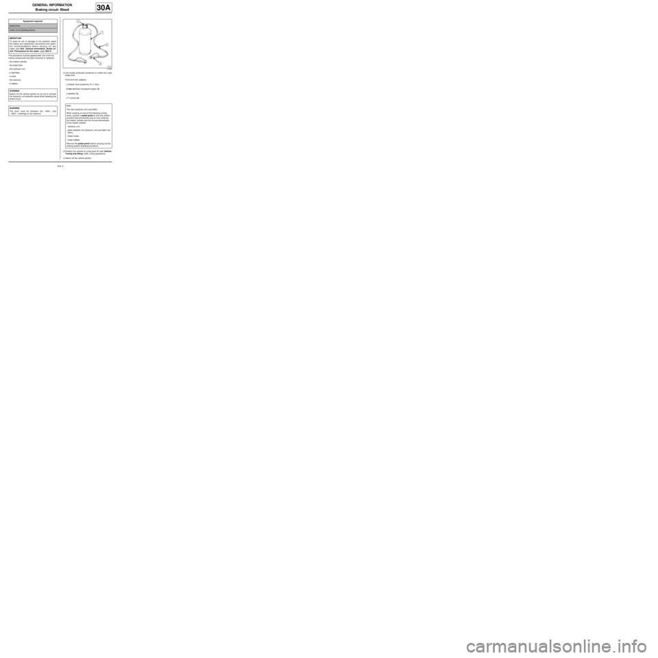
-a calliper.aUse locally produced containers to collect the used
brake fluid.
Front and rear callipers:
-2 washer fluid containers (1) (1 litre),
-4 mm diameter transparent pipes (2) ,
-4 pipettes (3) ,
-2 T-unions (4) .
aPosition the vehicle on a two-post lift (see Vehicle:
Towing and lifting) (02A, Lifting equipment).
aSwitch off the vehicle ignition. Equipment required
pedal press
brake circuit bleeding device
IMPORTANT
To avoid all risk of damage to the systems, apply
the safety and cleanliness instructions and opera-
tion recommendations before carrying out any
repair (see 30A, General information, Brake cir-
cuit: Precautions for the repair, page 30A-2) .
WARNING
Switch off the vehicle ignition so as not to activate
the hydraulic unit solenoid valves when bleeding the
brake circuit.
WARNING
The level must be between the « MIN » and
« MAX » markings on the reservoir.
115993
Note:
The new hydraulic unit is pre-filled.
When working on one of the following compo-
nents , position a pedal press to limit the outflow
of brake fluid and prevent any air from entering
the master cylinder and the circuits downstream
of the master cylinder:
-hydraulic unit,
-pipes between the hydraulic unit and brake cal-
lipers,
-brake hoses,
-brake calliper.
Remove the pedal press before carrying out the
braking system bleeding procedure.
Page 17 of 281
30A-13
GENERAL INFORMATION
Rigid brake pipe: Repair
30A
This procedure applies to copper pipes diameter 4.7
mm.
REPAIR
I - PIPE PREPARATION OPERATION
a
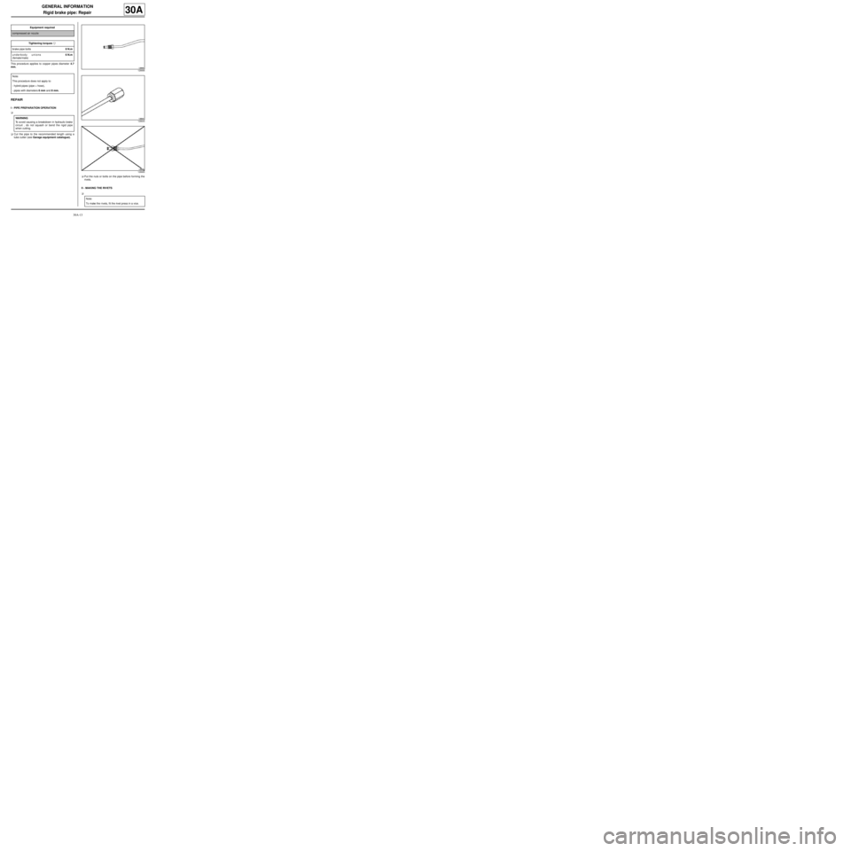
aCut the pipe to the recommended length using a
tube cutter (see Garage equipment catalogue).
aPut the nuts or bolts on the pipe before forming the
rivets.
II - MAKING THE RIVETS
a Equipment required
compressed air nozzle
Tightening torquesm
brake pipe bolts8 N.m
underbody unions
(female/male)6 N.m
Note:
This procedure does not apply to:
-hybrid pipes (pipe + hose),
-pipes with diameters 6 mm and 8 mm.
WARNING
To avoid causing a breakdown in hydraulic brake
circuit , do not squash or bend the rigid pipe
when cutting.
128666
128643
128665
Note:
To make the r ivets, fit the rivet press in a vice.
Page 20 of 281
30A-16
GENERAL INFORMATION
Rigid brake pipe: Repair
30A
a
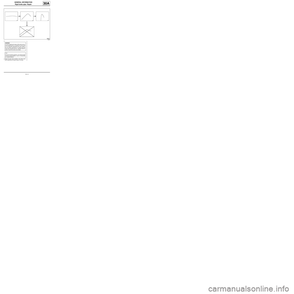
aShape the pipe using a bender, curve after curve,
while respecting the original shape of the pipe.
128814
WARNING
To avoid weakening the pipe, either bend once or
bend progressively by increasing the bend (that
is, by continually decreasing the curve radius).
Do not install a rigid pipe on a vehicle that may
have been bended and then unbended alterna-
tively to reach the correct curve radius.
Note:
During the bending operation, the required angle
should be passed slightly in order to compensate
for material elasticity.
Page 21 of 281
30A-17
GENERAL INFORMATION
Rigid brake pipe: Repair
30A
V - CHECKING BENDING
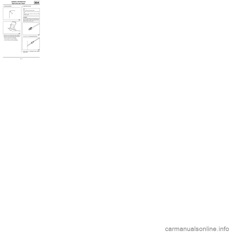
aCheck the out-of-roundness of the outer diameter at
the centre of the curve radius (2) using a sliding cal-
liper (the out-of-roundness of the outer diameter is
correct if it is less than 10% flattening):
-nominal diameter of the pipe: 4.75 mm,
-minimum diameter after bending: 4.30 mm.VI - REFITTING THE PIPE
a
aTorque tighten the brake pipe bolts (8 N.m).
aTorque tighten the underbody unions (female/
male) (6 N.m).
128664
128670
Note:
When refitting the rigid brake pipe:
-respect the original routing as much as possi-
ble,
-adjust the pipe routing by hand when fitting
inside the clips.
WARNING
Contact points between the rigid brake pipe and
the surrounding components could cause dam-
age to the pipe. In order to avoid these contacts,
adjust the pipe routing by hand.
128644
128646
Page 35 of 281
30A-31
GENERAL INFORMATION
Front axle assembly: Adjustment values
30A
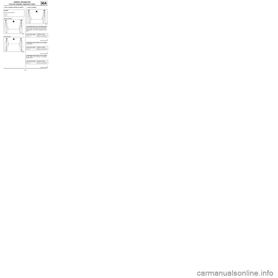
I - WHEEL ALIGNMENT: MEANING OF SYMBOLS
Toe-out: minus sign
Toe-in: plus signII - WHEEL ALIGNMENT
WARNING
Symbols used by RENAULT:
-toe-out: -
-toe-in: +
93011
93011-1
93011
EQUIPMENT LEVEL EA0 or EQUIPMENT LEVEL
EA1 or EQUIPMENT LEVEL EA3 or EQUIPMENT
LEVEL EA5 or EQUIPMENT LEVEL EAG or
EQUIPMENT LEVEL EZ2 or EQUIPMENT LEVEL
EZ4
Value (for two wheels) Position of vehicle
-0˚10’ ± 15’ Vehicle in running order
EQUIPMENT LEVEL SPORT, and 16" ALUMIN-
IUM WHEELS
Value (for two wheels) Position of vehicle
-0˚10’ ± 9’ Vehicle in running order
EQUIPMENT LEVEL SPORT, and 17" ALUMIN-
IUM WHEELS, and WITHOUT ADDITIONAL
SPORT PACK
Value (for two wheels) Position of vehicle
-0˚10’ ± 9’ Vehicle in running order
Page 42 of 281
30A-38
GENERAL INFORMATION
Rear axle assembly: Adjustment values
30A
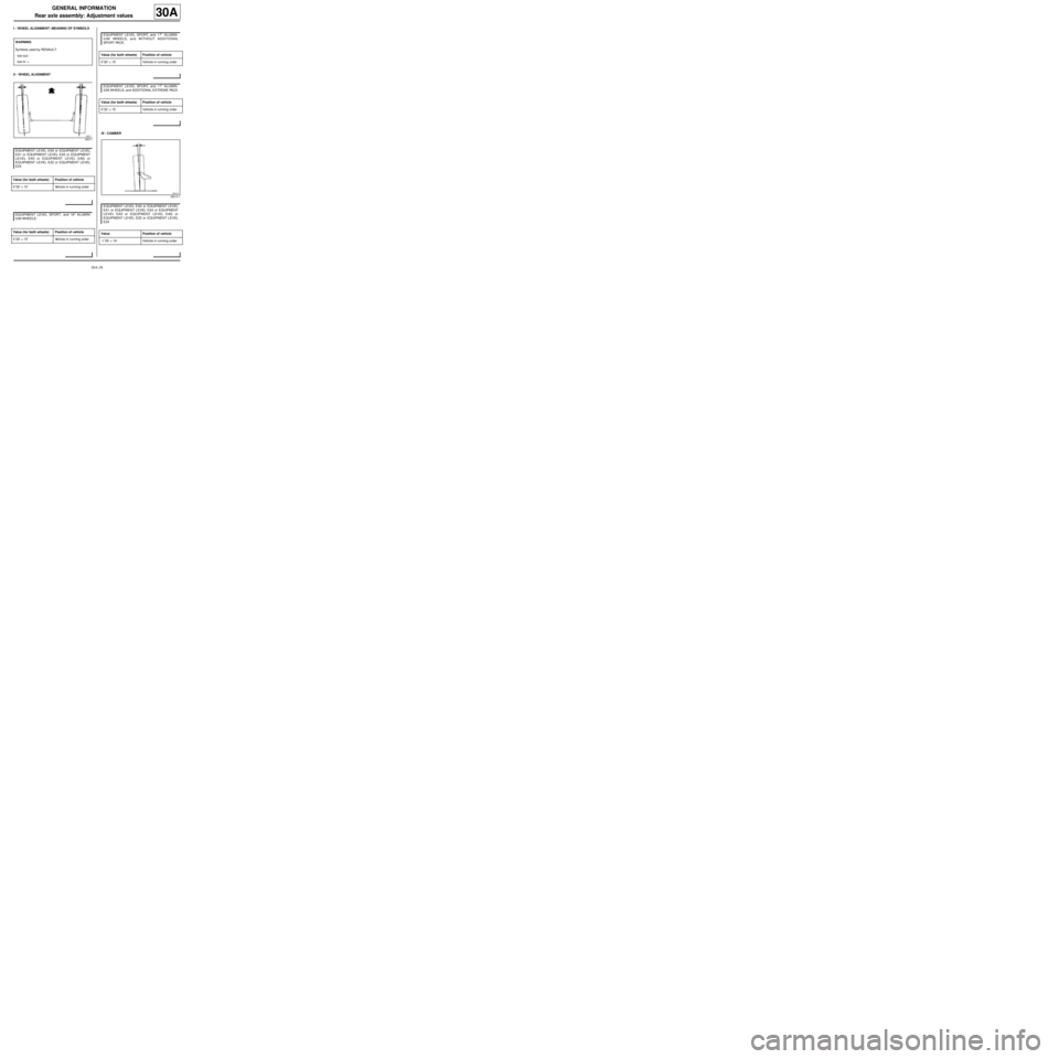
I - WHEEL ALIGNMENT: MEANING OF SYMBOLS
II - WHEEL ALIGNMENT
III - CAMBER WARNING
Symbols used by RENAULT:
-toe-out: -
-toe-in: +
93011
EQUIPMENT LEVEL EA0 or EQUIPMENT LEVEL
EA1 or EQUIPMENT LEVEL EA3 or EQUIPMENT
LEVEL EA5 or EQUIPMENT LEVEL EAG or
EQUIPMENT LEVEL EZ2 or EQUIPMENT LEVEL
EZ4
Value (for both wheels) Position of vehicle
0˚30’ ± 15’ Vehicle in running order
EQUIPMENT LEVEL SPORT, and 16" ALUMIN-
IUM WHEELS
Value (for both wheels) Position of vehicle
0˚20’ ± 15’ Vehicle in running order
EQUIPMENT LEVEL SPORT, and 17" ALUMIN-
IUM WHEELS, and WITHOUT ADDITIONAL
SPORT PACK
Value (for both wheels) Position of vehicle
0˚20’ ± 15’ Vehicle in running order
EQUIPMENT LEVEL SPORT, and 17" ALUMIN-
IUM WHEELS, and ADDITIONAL EXTREME PACK
Value (for both wheels) Position of vehicle
0˚22’ ± 15’ Vehicle in running order
93013-1
EQUIPMENT LEVEL EA0 or EQUIPMENT LEVEL
EA1 or EQUIPMENT LEVEL EA3 or EQUIPMENT
LEVEL EA5 or EQUIPMENT LEVEL EAG or
EQUIPMENT LEVEL EZ2 or EQUIPMENT LEVEL
EZ4
Value Position of vehicle
-1˚05’ ± 19’ Vehicle in running order
Page 45 of 281
31A-2
FRONT AXLE COMPONENTS
Front brake pads: Removal - Refitting
EQ UIPMENT LEVEL EA0 or EQUIPMENT LEVEL EA1 or EQUIPMENT LEVEL EA3 or EQUIPMENT LEVEL EA5
or EQUIPMENT LEVEL EAG or EQUIPMENT LEVEL EZ2 or EQUIPMENT LEVEL EZ4
31A
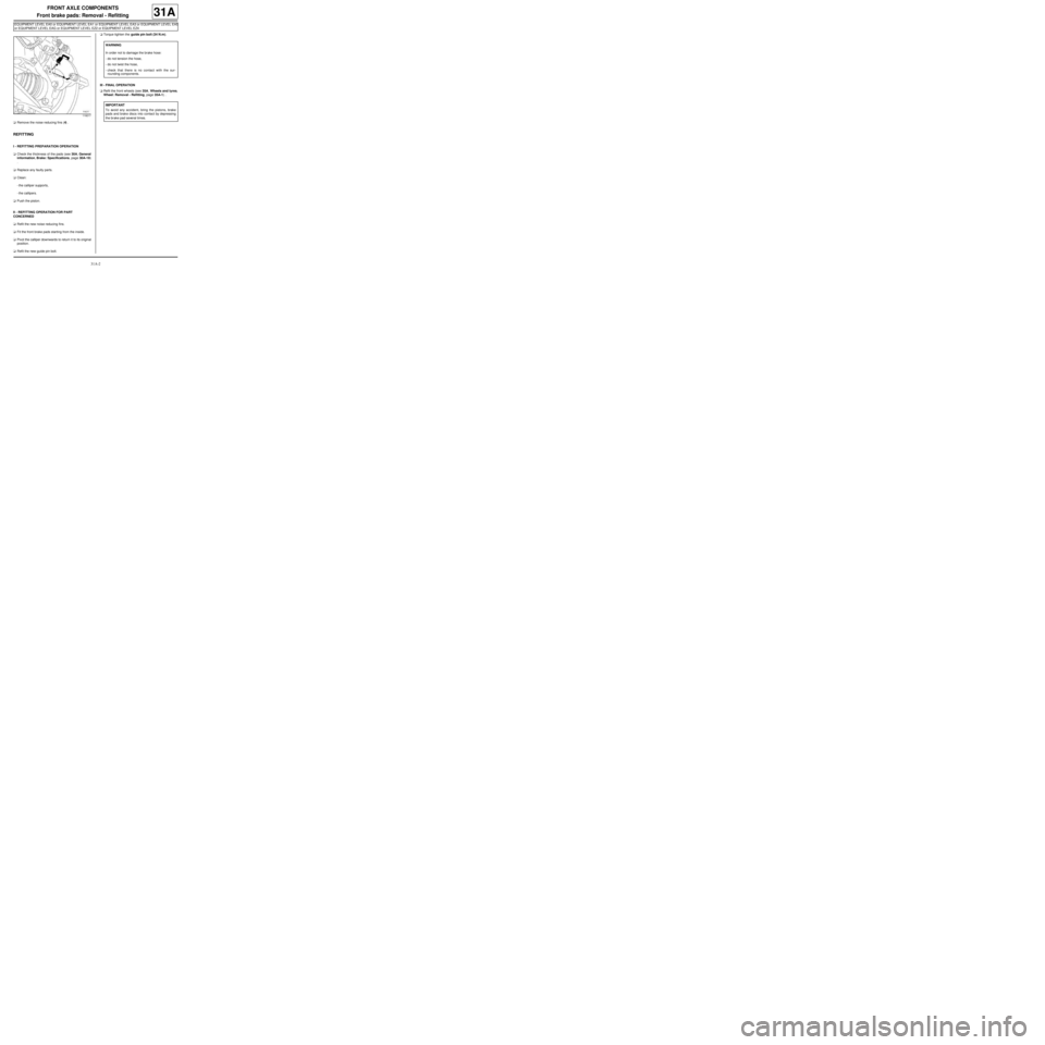
aRemove the noise reducing fins (4) .
REFITTING
I - REFITTING PREPARATION OPERATION
aCheck the thickness of the pads (see 30A, General
information, Brake: Specifications, page 30A-19)
.
aReplace any faulty parts.
aClean:
-the calliper supports,
-the callipers.
aPush the piston.
II - REFITTING OPERATION FOR PART
CONCERNED
aRefit the new noise reducing fins.
aFit the front brake pads starting from the inside.
aPivot the calliper downwards to return it to its original
position.
aRefit the new guide pin bolt.aTorque tighten the guide pin bolt (34 N.m).
III - FINAL OPERATION
aRefit the front wheels (see 35A, Wheels and tyres,
Wheel: Removal - Refitting, page 35A-1) .
119217
WARNING
In order not to damage the brake hose:
-do not tension the hose,
-do not twist the hose,
-check that there is no contact with the sur-
rounding components.
IMPORTANT
To avoid any accident, bring the pistons, brake
pads and brake discs into contact by depressing
the brake pad several times.
Page 46 of 281
31A-3
FRONT AXLE COMPONENTS
Front brake pads: Removal - Refitting
EQ UIPMENT LEVEL SPORT
31A
REMOVAL
I - REMOVAL PREPARATION OPERATION
aPosition the vehicle on a two-post lift (see Vehicle:
Towing and lifting) (02A, Lifting equipment).
aSet the wheels straight ahead.
aRemove the front wheels (see 35A, Wheels and ty-
res, Wheel: Removal - Refitting, page 35A-1) .II - REMOVAL OPERATION
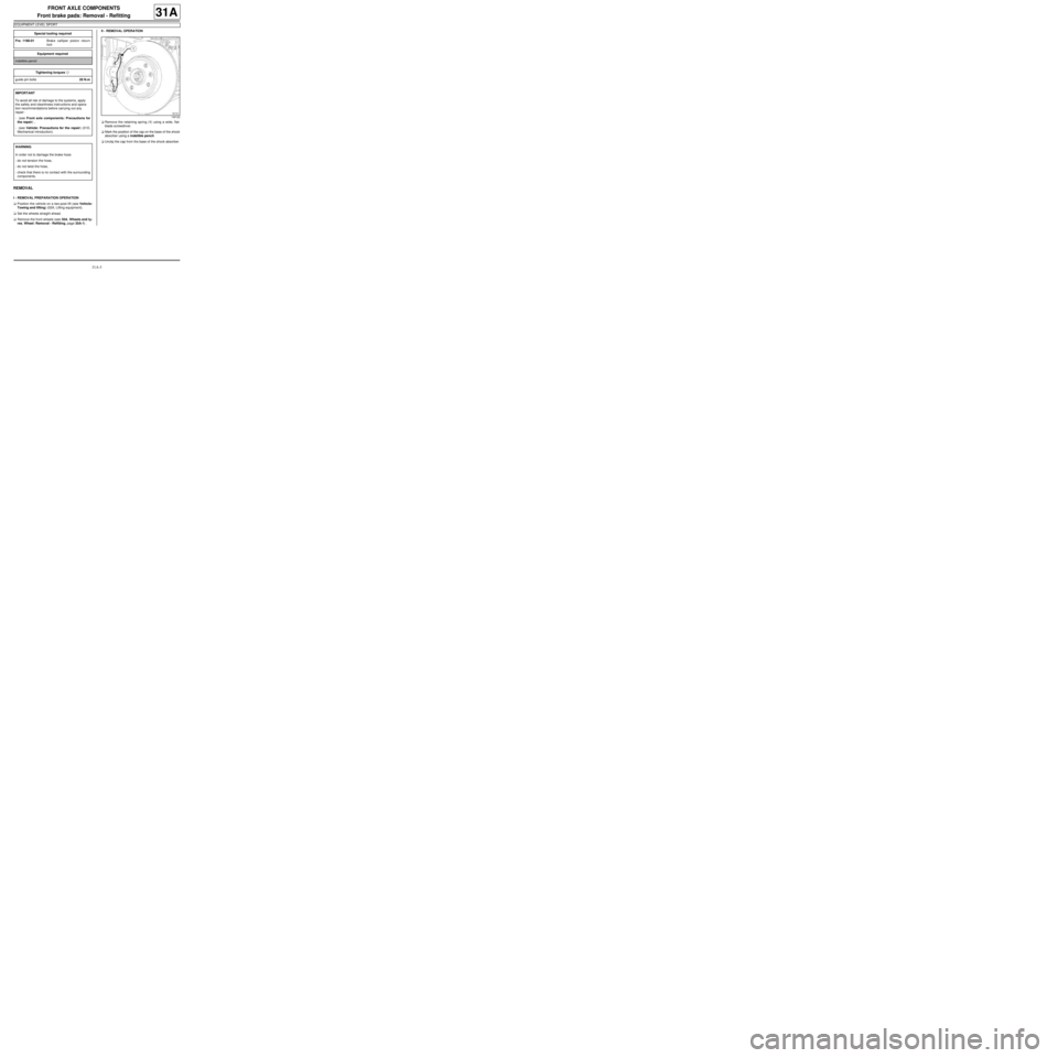
aRemove the retaining spring (1) using a wide, flat-
blade screwdriver.
aMark the position of the cap on the base of the shock
absorber using a indelible pencil.
aUnclip the cap from the base of the shock absorber. Special tooling required
Fre. 1190-01Brake calliper piston return
tool.
Equipment required
indelible pencil
Tightening torquesm
guide pin bolts28 N.m
IMPORTANT
To avoid all risk of damage to the systems, apply
the safety and cleanliness instructions and opera-
tion recommendations before carrying out any
repair:
- (see Front axle components: Precautions for
the repair) ,
- (see Vehicle: Precautions for the repair) (01D,
Mechanical introduction).
WARNING
In order not to damage the brake hose:
-do not tension the hose,
-do not twist the hose,
-check that there is no contact with the surrounding
components.
145122
Page 48 of 281
31A-5
FRONT AXLE COMPONENTS
Front brake pads: Removal - Refitting
EQ UIPMENT LEVEL SPORT
31A
II - REFITTING OPERATION
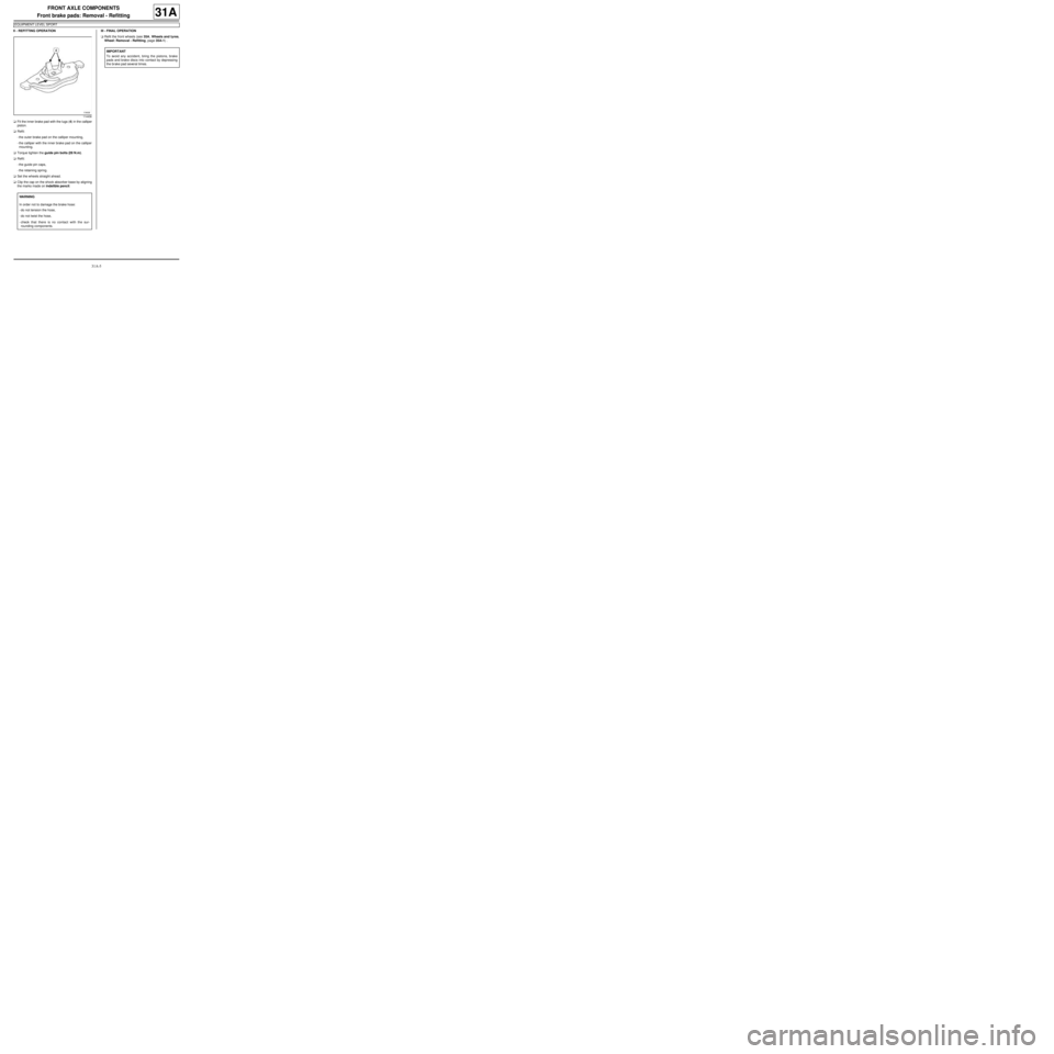
aFit the inner brake pad with the lugs (4) in the calliper
piston.
aRefit:
-the outer brake pad on the calliper mounting,
-the calliper with the inner brake pad on the calliper
mounting.
aTorque tighten the guide pin bolts (28 N.m).
aRefit:
-the guide pin caps,
-the retaining spring.
aSet the wheels straight ahead.
aClip the cap on the shock absorber base by aligning
the marks made on indelible pencil.III - FINAL OPERATION
aRefit the front wheels (see 35A, Wheels and tyres,
Wheel: Removal - Refitting, page 35A-1) .
114436
WARNING
In order not to damage the brake hose:
-do not tension the hose,
-do not twist the hose,
-check that there is no contact with the sur-
rounding components.
IMPORTANT
To avoid any accident, bring the pistons, brake
pads and brake discs into contact by depressing
the brake pad several times.