wiring RENAULT TWINGO 2009 2.G Electrical Equipment - Multiplexing Workshop Manual
[x] Cancel search | Manufacturer: RENAULT, Model Year: 2009, Model line: TWINGO, Model: RENAULT TWINGO 2009 2.GPages: 33, PDF Size: 0.18 MB
Page 13 of 33
88B-13V3 MR-413-X44-88B000$040.mif
MULTIPLEXING
Fault finding – Function88B
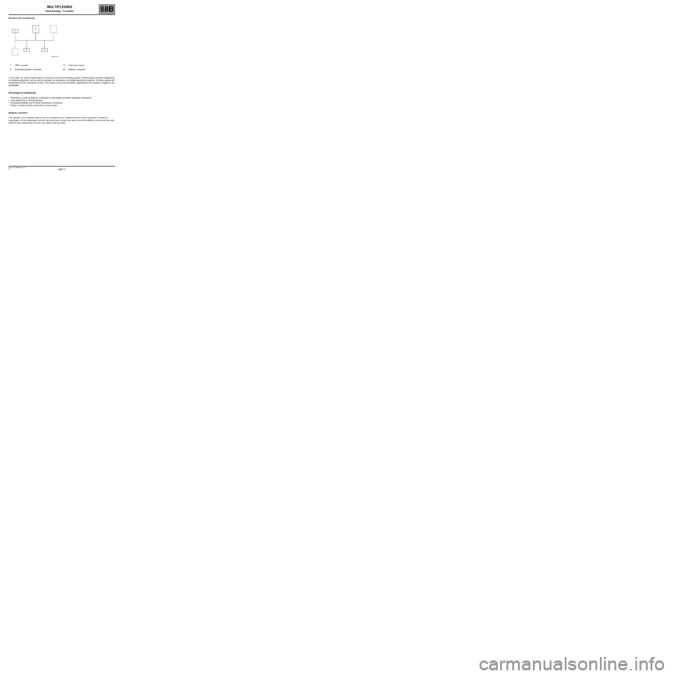
Solution with multiplexing
In this case, the vehicle speed signal is shared by the anti-lock braking system vehicle speed computer (depending
on vehicle equipment), and as many computers as necessary via a single electrical connection. All other signals are
transmitted via this connection as well. Thus there is only one connection regardless of the number of signals to be
exchanged.
Advantages of multiplexing
•Reduction in costs as there is a reduction in wire length and there are fewer connectors.
•Less weight due to wiring harness.
•Increased reliability due to there being fewer connectors.
•Easier to locate a faulty component in some cases.
Multiplex operation
The operation of a multiplex network can be compared to an underground line which transports a number of
passengers. All the passengers use the same line even though they get on and off at different points and they take
different trains depending on when they started their journeys.1ABS computer3Instrument panel
2Automatic gearbox computer4Injection computer
12
3 4
Page 17 of 33

88B-17V3 MR-413-X44-88B000$060.mif
88B
MULTIPLEX NETWORK CONFIGURATION
For the
CAN Vehicle network:
The tool displays the UCH and/or Airbag configurations.
The Configuration screen consists of two tabs for displaying and modifying the:
–The first tab, Multiplex network configuration, indicates the multiplex network version and the list of computers
defined as present on the multiplex network.
–The second tab, Configuration of computers which support fault finding, indicates the relevant diagram
number, and the list of computers defined as supporting fault finding with the RENAULT tool.
First repair the computers containing the multiplex network configuration (Airbag and UCH) in order to
display the screen with the multiplex network configuration diagram for the vehicle on which fault finding is
being run.
For the
CAN Multimedia network:
The tool presents the configuration of the A2/A3 display.
The Configuration screen consists of two tabs for displaying and modifying the:
–The first tab, Multiplex network configuration, indicates the multiplex network version and the list of computers
defined as present on the multiplex network.
–The second tab, Configuration of computers which support fault finding, indicates the relevant diagram
number, and the list of computers defined as supporting fault finding with the RENAULT tool.
NOTESThe configuration is entered with the ignition on; apply the forced + after ignition
feed procedure (see Introduction).
It can be run from the multiplex network test results screens.
WARNING: the network version number is 1.
This is the diagram version which changes each time the multiplex network wiring is modified on this vehicle.
WARNING: the network version number is 1.
This is the diagram version which changes each time the multiplex network wiring is modified on this vehicle.
MULTIPLEXING
Fault finding – Configuration
Page 22 of 33
88B-22
AFTER REPAIRRun the multiplex network test again using the diagnostic tool.
Clear the stored faults on all the computers connected to the network.
Deal with any other faults.
V3 MR-413-X44-88B000$070.mif
MULTIPLEXING
Fault finding – Interpretation of faults88B
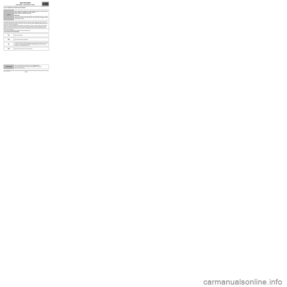
FAULTY SEGMENT ON THE MULTIPLEX NETWORK
NOTESFirst check that the computer at the end of the faulty segment is properly powered
(earth, + battery, + accessories or + after ignition).
Always check the computer conformity.
IMPORTANT
It may be that the tool cannot exactly determine which segment(s) are faulty. It will then
suggest several segments that could be faulty. In this event, repair the segment closest
to the diagnostic socket.
Isolate the faulty segment by disconnecting both ends of the segment. Check the condition of the connectors.
Check the continuity and insulation of the CAN H and CAN L lines (connections 133B and 133C) between the two
connectors of the isolated segment.
Refer to the vehicle's multiplex network diagram for the allocation of tracks on the computers and connections.
Perform the necessary operations to check the continuity of the two lines (for example, replacing the wiring).
Make sure that the computer present in the vehicle is compatible and that the data it is producing is correct.
Reconnect the segment.
Carry out the multiplex network test again using the diagnostic tool.
Is the segment still declared faulty?
NOEnd of fault finding.
YESAre there other faulty segments?
NO
Repeat the multiplex network tests to ensure the continuity and insulation of the CAN
H and CAN L lines (connections 133B and 133C) between the end of the faulty
segment and the diagnostic socket.
YESApply the same procedure to each segment.
Page 25 of 33
88B-25
AFTER REPAIRRun the multiplex network test again using the diagnostic tool.
Clear the stored faults on all the computers connected to the network.
Deal with any other faults.
V3 MR-413-X44-88B000$070.mif
MULTIPLEXING
Fault finding – Interpretation of faults88B
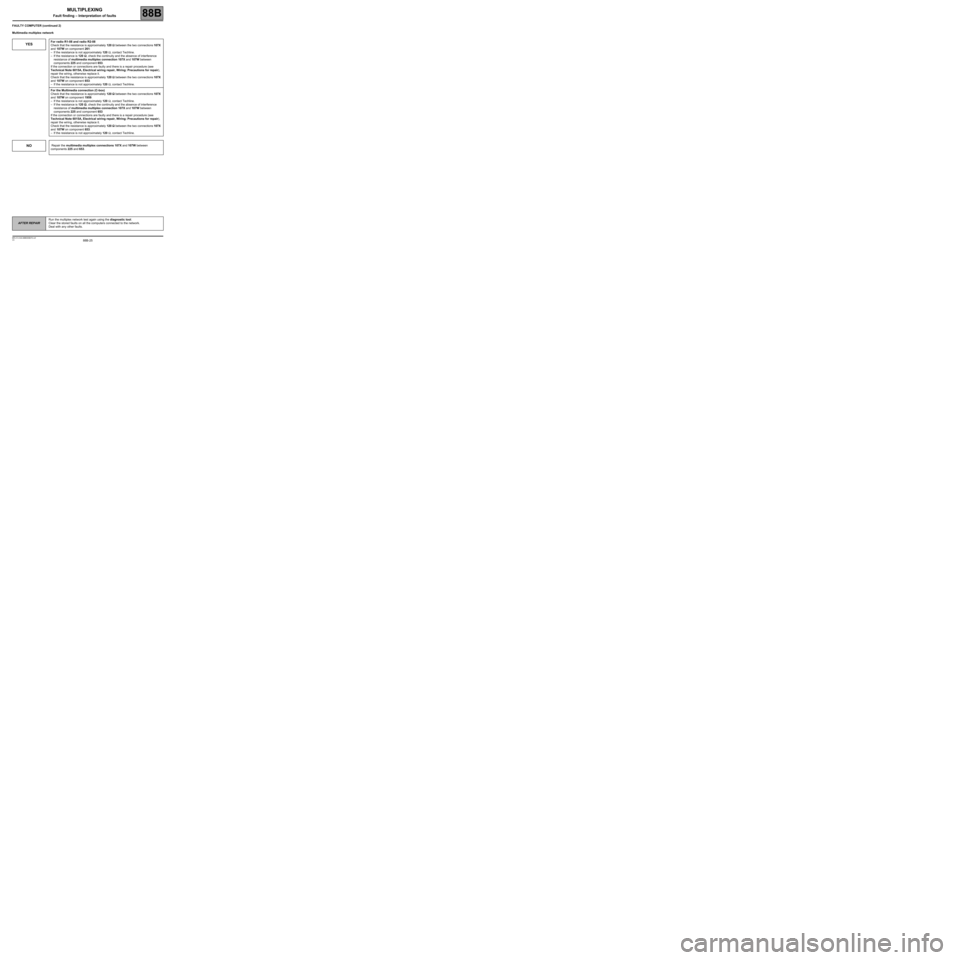
FAULTY COMPUTER (continued 2)
Multimedia multiplex network
YESFor radio R1-08 and radio R2-08
Check that the resistance is approximately 120 ΩΩ Ω Ω
between the two connections 107X
and 107W on component 261:
–If the resistance is not approximately 120 Ω, contact Techline.
–If the resistance is 120 ΩΩ Ω Ω
, check the continuity and the absence of interference
resistance of multimedia multiplex connection 107X and 107W between
components 225 and component 653.
If the connection or connections are faulty and there is a repair procedure (see
Technical Note 6015A, Electrical wiring repair, Wiring: Precautions for repair),
repair the wiring, otherwise replace it.
Check that the resistance is approximately 120 ΩΩ Ω Ω
between the two connections 107X
and 107W on component 653:
–If the resistance is not approximately 120 Ω, contact Techline.
For the Multimedia connection (C-box)
Check that the resistance is approximately 120 ΩΩ Ω Ω
between the two connections 107X
and 107W on component 1959:
–If the resistance is not approximately 120 Ω, contact Techline.
–If the resistance is 120 ΩΩ Ω Ω
, check the continuity and the absence of interference
resistance of multimedia multiplex connection 107X and 107W between
components 225 and component 653
If the connection or connections are faulty and there is a repair procedure (see
Technical Note 6015A, Electrical wiring repair, Wiring: Precautions for repair),
repair the wiring, otherwise replace it.
Check that the resistance is approximately 120 ΩΩ Ω Ω
between the two connections 107X
and 107W on component 653:
–If the resistance is not approximately 120 Ω, contact Techline.
NO Repair the multimedia multiplex connections 107X and 107W between
components 225 and 653.
Page 26 of 33
88B-26
AFTER REPAIRRun the multiplex network test again using the diagnostic tool.
Clear the stored faults on all the computers connected to the network.
Deal with any other faults.
V3 MR-413-X44-88B000$070.mif
MULTIPLEXING
Fault finding – Interpretation of faults88B
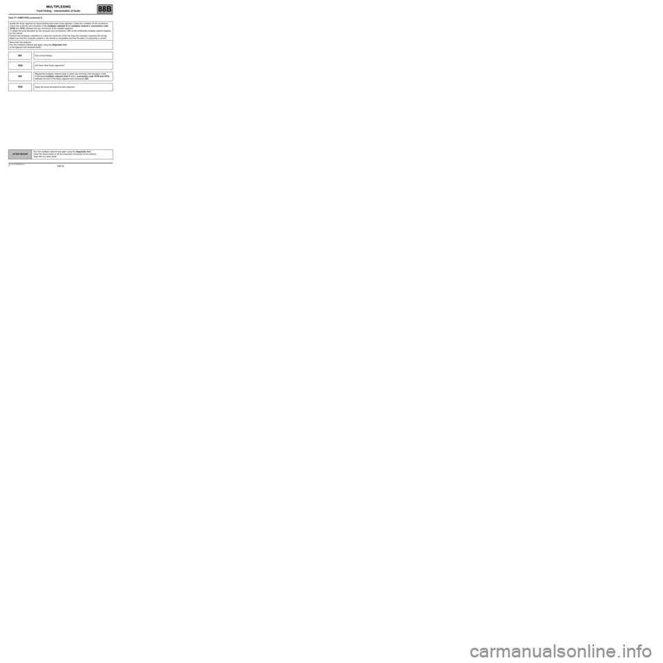
FAULTY COMPUTER (continued 3)
Isolate the faulty segment by disconnecting both ends of the segment. Check the condition of the connectors.
Check the continuity and insulation of the multiplex network H and multiplex network L (connection code
107W and 107X) between the two connectors of the isolated segment.
To obtain the track allocation for the computer and connections, refer to the multimedia multiplex network diagram
for the vehicle.
Perform the necessary operations to check the continuity of the two lines (for example, replacing the wiring).
Make sure that the computer present in the vehicle is compatible and that the data it is producing is correct.
Reconnect the segment.
Run the multiplex network test again using the diagnostic tool.
Is the segment still declared faulty?
NOEnd of fault finding.
YESAre there other faulty segments?
NO
Repeat the multiplex network tests to check the continuity and insulation of the
multimedia multiplex network lines H and L (connection code 107W and 107X)
between the end of the faulty segment and component 225.
YESApply the same procedure to each segment.
Page 31 of 33
88B-31V3 MR-413-X44-88B000$080.mif
MULTIPLEXING
Fault finding – Fault finding chart88B
ALP 1
CONTINUED 3
Check the following connections on the diagnostic socket:
BP 19 + Battery
NAM and MAM (or MAN) Earth
If the connection or connections are faulty and there is a repair procedure (see Technical Note 6015A, Electrical
wiring repair, Wiring: Precautions for repair), repair the wiring, otherwise replace the wiring.
Computer connected to multiplex line V
If the fault is still present, check the continuity and the insulation of the following connections:
133B of component 225.
133C of component 225.
Use a multimeter to check that the voltages at the terminals of component 225 are approximately:
–2.5 V between CAN H (133B) and earth (NAM and MAM) (Average values)
–2.5 V between CAN L (133C) and earth (NAM and MAM) (Average values).
Computer connected to Multimedia multiplex line
If the fault is still present, check the continuity and the insulation of the following connections:
107W of component 225.
107X of component 225.
Use a multimeter to check that the voltages at the terminals of component 225 are approximately:
–2.5 V between CAN H (107W) and earth (NAM and MAM) (Average values)
–2.5 V between CAN L (107X) and earth (NAM and MAM) (Average values).
Refer to the Introduction - Repair advice to detect a short circuit on the vehicle's multiplex network.