parking sensors RENAULT TWINGO 2009 2.G Electrical Equipment - Parking Distance Control Workshop Manual
[x] Cancel search | Manufacturer: RENAULT, Model Year: 2009, Model line: TWINGO, Model: RENAULT TWINGO 2009 2.GPages: 43, PDF Size: 0.18 MB
Page 10 of 43

PARKING DISTANCE CONTROL
87F
87F - 10V2 MR-413-X44-87F000$240_eng.mif
Vdiag No.: 04 08PARKING DISTANCE CONTROL
Fault finding - Role of components
Description of operation
The system consists of four sensors built into the rear bumper, a computer and a buzzer.
The system assists the driver during parking manoeuvres by warning of any obstacles to the rear of the vehicle.
The sensors and the computer calculate the distance between the vehicle and any obstacles.
The ultrasonic sensors are able to detect different obstacles such as:
–A wall.
–A post.
–A fence.
–A square section tube.
–Runner.
The sensors operate over a distance range from between 26 to 30 cm minimum and 150 cm maximum. If an
obstacle is less than 25 cm away, the signal received (after coming into contact with the obstacle) will be disrupted
by the signal emitted by the sensor, therefore, it is possible that measurements made at this distance will be incorrect
The driver is informed of the distances by a buzzer.
The system only works when the vehicle is in reverse gear. Activation is indicated by a brief 0.5 second activation
sound.
The buzzer is activated when the vehicle is 150 cm from the obstacle. As the distance diminishes, the frequency of
the buzzer increases. When the distance reaches 20 - 30 cm, the buzzer becomes continuous.
–The system can only be activated with + after ignition feed and reverse gear engaged.
MR-413-X44-87F000$240_eng.mif
Page 12 of 43
PARKING DISTANCE CONTROL
Fault finding - Configurations and programming87F
87F - 12V2 MR-413-X44-87F000$330_eng.mif
Vdiag No.: 04 08PARKING DISTANCE CONTROL
Fault finding - Configurations and programming
CONFIGURATION AFTER REPLACING THE COMPUTER
After replacing the computer, configure the parking distance control computer with the vehicle type using
configuration CF005 Vehicle identification (repair mode menu, diagnostic tool configuration function).
The configuration adapts the sensors' detection field to the type of body.
Activation of the parking proximity sensor is indicated by a brief 0.5 second activation sound (vehicle in reverse
gear).
After having configured the computer, check that the configuration has taken effect by reading the configuration
LC005 Vehicle identification.
SETTING OPTIONS
The volume and the tone of the buzzer can be changed if the customer desires.
Configuration CF001 “Buzzer volume” is used to adjust the volume of the buzzer.
There are five selections:
–ZERO,
–LOW,
–MEDIUM,
–HIGH.
–MAXIMUM
Configuration function CF006 Pitch adjustment is used to adjust the pitch of the buzzer.
There are three choices:
–800 Hz,
–1000 Hz,
–2000 Hz (high pitch).
After configuring the computer, check that these configurations have been registered correctly using configuration
readings LC001 “Buzzer volume” and LC006 “Tone adjustment”. Note:
The system must not be in “Detection” mode during this configuration as the buzzer will remain active until the next
time the + after ignition feed is cut off.
Note:
The system must not be in “Detection” mode during the configuration as the buzzer will remain active until the next
time the + after ignition feed is cut off.
MR-413-X44-87F000$330_eng.mif
Page 23 of 43
PARKING DISTANCE CONTROL
Fault finding - Interpretation of faults
87F
87F - 23V2 MR-413-X44-87F000$462_eng.mif
Vdiag No.: 04 08
DF007
PRESENT
OR
STOREDSENSOR SUPPLY VOLTAGE
CC.0: Short circuit to earth
NOTESConditions for applying the fault finding procedure to stored faults:
The fault reappears present or stored after its has been cleared, the ignition is switched
on and off again and reverse gear is selected.
Special notes:
The sensors are directly supplied with + 12 V by the computer.
With the parking proximity sensor computer 16-track connector connected and with the ignition on, measure the
sensor power supply coming from the computer. The voltage should be equal to the battery voltage (± 0.5 V)
when measuring between connections 151U (+ 12 V) and 151V (earth).
If there is no + 12 V supply between connections 151U and 151V, remove the rear bumper to access the sensors.
Switch off the ignition, and disconnect the parking proximity sensor computer to check the insulation and
continuity and the absence of interference resistance on the following connections:
●Connection code 151U,
●Connection code 151V.
Between components 1222 and 1218, 1219, 1220, 1221.
If the connection or connections are faulty and if there is a repair procedure (see Technical Note 6015A, Electrical
wiring repair, Wiring: Precautions for repair), repair the wiring or replace it.
If the sensor power supply is correct (no short circuit), reconnect the computer connector and four sensor
connectors.
Turn on the ignition and disconnect the sensors, one at a time, to see if any of the sensors causes the power supply
to drop. Replace the defective sensor.
If the sensor supply lines are not correct, check the presence and condition of fuse F6 (15A); replace it if necessary.
Check for the + 12 V supply on connection AP3 between components of component 1222 and 1016. Check for
earth on connection MG between components 1222 and earth MG.
If the fault is still present, contact the Techline.
AFTER REPAIRClear the stored faults.
Follow the instructions to confirm repair.
Deal with any other faults.
AAP_V04_DEF007/AAP_V08_DEF007
Page 27 of 43
PARKING DISTANCE CONTROL
Fault finding - Conformity check
87F
87F - 27V2 MR-413-X44-87F000$528_eng.mif
Vdiag No.: 04 08
MAIN SCREEN (CONTINUED)
NOTESOnly perform this conformity check after a thorough check with the diagnostic tool.
Conditions for applying the fault finding procedure: ignition on.
Order FunctionParameter or Status
checked or ActionDisplay and Notes Fault finding
5Buzzer controlET002:Buzzer controlACTIVE when the buzzer
sounds.
INACTIVE if not.In the event of a fault,
consult the interpretation
of status ET002.
6Proximity
sensorsPR001:Left-hand
outer sensor
distance26 cm < X < 150 cm
depending on the distance
from the obstacle (“out of
range” value: 0 cm).In the event of a fault, refer
to the interpretation of the
parameter PR001.
PR002:Left-hand
inner sensor
distance26 cm < X < 150 cm
depending on the distance
from the obstacle (“out of
range” value: 0 cm).If there is a fault, refer to
the interpretation of
parameter PR002.
PR003:Right-hand
outer sensor
distance26 cm < X < 150 cm
depending on the distance
from the obstacle (“out of
range” value: 0 cm).In the event of a fault,
consult the interpretation
of parameter PR003.
PR004:Right-hand
inner sensor
distance26 cm < X < 150 cm
depending on the distance
from the obstacle (“out of
range” value: 0 cm).If there is a fault, refer to
the interpretation of
parameter PR004.
PR005:Shortest
distance
calculated26 cm < X < 150 cm
depending on the distance
from the obstacle (value
out of range or less than
30 cm: 0 cm).If there is a fault, refer to
the interpretation of
parameter PR005.
7Caravan towbarPR026:Distance from
the caravan
attachment26 cm < X < 35 cm
This distance allows the
threshold point (0 cm)
from the rear of the vehicle
to be redetermined
according to the length of
the caravan towbarIn the event of a
permanent or erratic
warning signal, check that
no components are
disrupting the
measurement (sticker,
mud, snow on the rear
bumper, etc.) then
increase the distance of
the caravan towbar cm by
cm, using configuration
VP003 “Caravan towbar
distance”.
Page 35 of 43
PARKING DISTANCE CONTROL
Fault finding - Interpretation of parameters
87F
87F - 35V2 MR-413-X44-87F000$792_eng.mif
Vdiag No.: 04 08PARKING DISTANCE CONTROL
Fault finding - Interpretation of parameters
PR001
PR002
PR003
PR004
LEFT-HAND OUTER SENSOR DISTANCE
LEFT-HAND INNER SENSOR DISTANCE
RIGHT-HAND OUTER SENSOR DISTANCE
RIGHT-HAND INNER SENSOR DISTANCE
NOTESSpecial notes:
Before searching for a fault with these parameters, make sure no fault is present or
stored. If there is a fault, apply the interpretation for the fault detected by the
diagnostic tool.
Note:
The ultrasonic sensors are very fragile. Therefore, when removing the rear bumper,
be careful not to scratch them.
If the distance displayed equals 0 cm, there are two possible reasons:
1no obstacle has been detected (therefore this is the default value)
2The sensor is malfunctioning, check that there are none of the following faults:
DF002 “LEFT-HAND OUTER SENSOR”, DF003 “LEFT-HAND INNER SENSOR”,
DF004 “RIGHT-HAND OUTER SENSOR”, DF005 '“RIGHT-HAND INNER
SENSOR” and apply the relevant fault finding procedure
Wen the vehicle is close to an obstacle (between 26 and 150 cm), check that the distance evaluated corresponds
to the distance displayed by the diagnostic tool (PR001 to PR004).
If the distance is inconsistent when there is an obstacle present, check that there is nothing interfering with the
measurement (sticker, mud, snow on the rear bumper, etc.).
If the distances displayed by the sensors are inconsistent, check the condition of the sensor(s), check the condition
of the button using status ET003 “Parking distance control function” and ET004 “Parking distance control
switch”. There must be no scratches on the detection component (outer metal section) of the sensors.
Replace the defective sensor.
If the fault is still present, apply the fault finding procedure to the sensor whose distance parameter is incorrect
(even if the diagnostic tool does not report a fault).
AFTER REPAIRRepeat the conformity check from the start.
AAP_V04_ PR001/AAP_V04_ PR002/AAP_V04_ PR003/AAP_V04_ PR004/
AAP_V08_ PR001/AAP_V08_ PR002/AAP_V08_ PR003/AAP_V08_ PR004
MR-413-X44-87F000$792_eng.mif
Page 36 of 43
PARKING DISTANCE CONTROL
Fault finding - Interpretation of parameters
87F
87F - 36V2 MR-413-X44-87F000$792_eng.mif
Vdiag No.: 04 08
PR005
SHORTEST DISTANCE CALCULATED
NOTESSpecial notes:
Before searching for a fault with this parameter, make sure that no fault is present or
stored. If there is a fault, apply the interpretation for the fault detected by the
diagnostic tool.
Note:
The ultrasonic sensors are very fragile. Therefore, when removing the rear bumper,
be careful not to scratch them.
This parameter is an average calculated by the computer when an obstacle is
placed between two sensors.
When below 30 cm, the estimated distance is displayed as 0 cm (critical detection
zone with constant warning sound).
With the vehicle close to an obstacle (between 0 and 150 cm), check whether the calculated distance is consistent.
If the distance is inconsistent when there is an obstacle present, check that there is nothing interfering with the
measurement (sticker, mud, snow on the rear bumper, etc.).
If the distance calculated is still inconsistent or if it is continuously displayed as 255 cm, check the condition of the
sensors; the detection part (metallic outer part) must not have any scratches.
Replace the defective sensor.
If the fault is still present, apply the fault finding procedure to the sensor with the inconsistent distance parameter
(even if the diagnostic tool does not detect a fault), consult interpretation of faults, DF002 “Left-hand outer
sensor”, DF003 “Left-hand inner sensor”, DF004 “Right-hand outer sensor”, DF005 “Right-hand inner
sensor”.
AFTER REPAIRRepeat the conformity check from the start.
AAP_V04_ PR005/AAP_V08_ PR005
Page 40 of 43
PARKING DISTANCE CONTROL
Fault finding - Fault Finding Chart
87F
87F - 40V2 MR-413-X44-87F000$924_eng.mif
Vdiag No.: 04 08
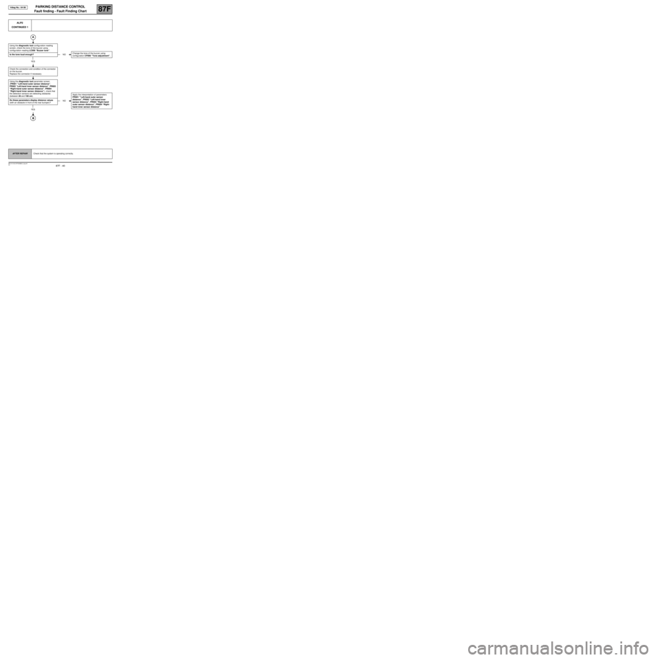
ALP2
CONTINUED 1
Using the diagnostic tool configuration reading
screen, check the tone of the buzzer using
configuration reading LC006 “Buzzer tone”.
Is the tone loud enough?
YES
Check the connection and condition of the connector
on the buzzer.
Replace the connector if necessary.
Using the diagnostic tool parameter screen
(PR001 “Left-hand outer sensor distance”,
PR002 “Left-hand inner sensor distance”, PR003
“Right-hand outer sensor distance”, PR004
“Right-hand inner sensor distance”), check that
the detection sensors are detecting obstacles
(between 26 and 150 cm).
Do these parameters display distance values
(with an obstacle in front of the rear bumper)?
YES
NOChange the tone of the buzzer using
configuration CF006 “Tone adjustment”.
NOApply the interpretation of parameters
PR001 '“Left-hand outer sensor
distance”, PR002 “Left-hand inner
sensor distance”, PR003 “Right-hand
outer sensor distance”, PR004 “Right-
hand inner sensor distance”
AFTER REPAIRCheck that the system is operating correctly.
Page 43 of 43
PARKING DISTANCE CONTROL
Fault finding - Fault Finding Chart
87F
87F - 43V2 MR-413-X44-87F000$924_eng.mif
Vdiag No.: 04 08
ALP4 buzzer sounds continuously (with caravan attachment)
NOTESOnly investigate this customer complaint after a full check using the diagnostic tool
(there must be no present or stored faults).
Make sure it is a Renault caravan attachment.
Check that the cover is correctly aligned with the caravan towing
hitch.
If it is incorrectly aligned, realign it or remove it.
Is the fault still present?
YES
Using the diagnostic tool, gradually increase the distance between the central sensors and the ball on the caravan
attachment centimetre by centimetre (this distance enables the threshold point to be redetermined (0 cm) from the
rear of the vehicle depending on the length of the caravan attachment) using configuration VP003 “Caravan
attachment distance” (maximum distance: 35 cm). The caravan attachment distance can be checked with
parameter PR026.
End of fault finding procedure.
NOEnd of fault finding
procedure.
AFTER REPAIRCheck that the system is operating correctly.
AAP_V04_ ALP4/AAP_V08_ ALP4