engine RENAULT TWINGO 2009 2.G Electrical Equipment - Petrol Injection Workshop Manual
[x] Cancel search | Manufacturer: RENAULT, Model Year: 2009, Model line: TWINGO, Model: RENAULT TWINGO 2009 2.GPages: 348
Page 319 of 348
17B-319V7 MR-413-X44-17B000$172.mif
PETROL INJECTION
Fault finding – Interpretation of parameters17B
SIM 32 injection
Program no.: D3
Vdiag No.: 44, 4C, 50
and 54
PR587MOTORISED THROTTLE VALVE LOWER STOP, GANG 1
PARAMETER
DEFINITIONThis parameter indicates the motorised throttle lower stop position for gang 1 in volts.
NOTESSpecial notes:
Only perform these tests if the parameters do not correspond with the system operation
programming.
Conformity check: Engine stopped and ignition on, or engine running, and engine coolant temperature
> 80˚C.
The value should be:
PR587 ≈ 0.5 V.
In the event of a fault, apply the interpretation of DF095 Throttle potentiometer circuit gang 1 and DF096
Throttle potentiometer circuit gang 2.
SIM32_V44_PR587 / SIM32_V4C_PR587 / SIM32_V50_PR587 / SIM32_V54_PR587
AFTER REPAIRCarry out a road test, then check with the diagnostic tool.
Page 320 of 348
17B-320V7 MR-413-X44-17B000$172.mif
PETROL INJECTION
Fault finding – Interpretation of parameters17B
SIM 32 injection
Program no.: D3
Vdiag No.: 44, 4C, 50
and 54
PR588MOTORISED THROTTLE VALVE LOWER STOP GANG 2
PARAMETER
DEFINITIONThis parameter indicates the motorised throttle lower stop position for gang 2 in volts.
NOTESSpecial notes:
Only perform these tests if the parameters do not correspond with the system operation
programming.
Conformity check: Engine stopped and ignition on, or engine running, and engine coolant temperature
> 80˚C.
The value should be:
PR588 ≈ 4.5 V.
In the event of a fault, apply the interpretation of DF095 Throttle potentiometer circuit gang 1 and DF096
Throttle potentiometer circuit gang 2.
SIM32_V44_PR588 / SIM32_V4C_PR588 / SIM32_V50_PR588 / SIM32_V54_PR588
AFTER REPAIRCarry out a road test, then check with the diagnostic tool.
Page 321 of 348
17B-321V7 MR-413-X44-17B000$172.mif
PETROL INJECTION
Fault finding – Interpretation of parameters17B
SIM 32 injection
Program no.: D3
Vdiag No.: 44, 4C, 50
and 54
PR589MOTORISED THROTTLE VALVE UPPER STOP, GANG 1
PARAMETER
DEFINITIONThis parameter indicates the motorised throttle upper stop position for gang 1 in volts.
NOTESSpecial notes:
Only perform these tests if the parameters do not correspond with the system operation
programming.
Conformity check: Engine stopped and ignition on, or engine running, and engine coolant temperature
> 80˚C.
The value should be:
PR589 ≈ 0.9 V.
In the event of a fault, apply the interpretation of DF095 Throttle potentiometer circuit gang 1 and DF096
Throttle potentiometer circuit gang 2.
SIM32_V44_PR589 / SIM32_V4C_PR589 / SIM32_V50_PR589 / SIM32_V54_PR589
AFTER REPAIRCarry out a road test, then check with the diagnostic tool.
Page 322 of 348
17B-322V7 MR-413-X44-17B000$172.mif
PETROL INJECTION
Fault finding – Interpretation of parameters17B
SIM 32 injection
Program no.: D3
Vdiag No.: 44, 4C, 50
and 54
PR590MOTORISED THROTTLE VALVE UPPER STOP GANG 2
PARAMETER
DEFINITIONThis parameter indicates the motorised throttle upper stop position for gang 2 in volts.
NOTESSpecial notes:
Only perform these tests if the parameters do not correspond with the system operation
programming.
Conformity check: Engine stopped and ignition on, or engine running, and engine coolant temperature
> 80˚C.
The value should be:
PR590 ≈ 4 V.
In the event of a fault, apply the interpretation of DF095 Throttle potentiometer circuit gang 1 and DF096
Throttle potentiometer circuit gang 2.
SIM32_V44_PR590 / SIM32_V4C_PR590 / SIM32_V50_PR590 / SIM32_V54_PR590
AFTER REPAIRCarry out a road test, then check with the diagnostic tool.
Page 323 of 348
17B-323V7 MR-413-X44-17B000$172.mif
PETROL INJECTION
Fault finding – Interpretation of parameters17B
SIM 32 injection
Program no.: D3
Vdiag No.: 44, 4C, 50
and 54
For CLIO III or MODUS only
PR743ALCOHOL LEVEL ESTIMATED IN THE TANK
PARAMETER
DEFINITIONThis parameter is used to estimate the percentage of alcohol contained in the petrol in
the main tank.
NOTESThere must be no present or stored faults.
Refer to CLIO III or MODUS Wiring Diagram Technical Note.
Conformity check: Engine stopped and ignition on, or engine running, and engine coolant temperature
> 80˚C.
This percentage must be between:
0 < PR743 < 100%
This parameter allows the computer to estimate the alcohol level contained in the petrol.
Status ET671 Alcohol level programming should be COMPLETED. This indicates that the percentage of alcohol
in the tank has been detected.
If status ET671 Alcohol level programming is NOT COMPLETED, repeat the programming procedure (see
Configurations and programming, Alcohol level programming).
Disconnect the battery and the injection computer.
Check the cleanliness and condition of the connections
Using the universal bornier, check the insulation and continuity on the following connections:
●3GH between components 887 and 120.
●3GK between components 887 and 120.
If the connection or connections are faulty and there is a repair procedure (see Technical Note 6015A, Electrical
wiring repair, Wiring: Precautions for repair), repair the wiring, otherwise replace it.
If the fault is still present, replace the upstream oxygen sensor.
If the fault is still present, contact the Techline.
SIM32_V44_PR743 / SIM32_V4C_PR743 / SIM32_V50_PR743 / SIM32_V54_PR743
AFTER REPAIRRepeat the conformity check from the start.
Page 324 of 348
17B-324V7 MR-413-X44-17B000$172.mif
PETROL INJECTION
Fault finding – Interpretation of parameters17B
SIM 32 injection
Program no.: D3
Vdiag No.: 44, 4C, 50
and 54
* OCS: Oil Control System.
PR873OIL OXIDATION SIGNAL
(except D7F800 and D4F772)
PARAMETER
DEFINITIONThis parameter indicates the distance of the vehicle when the oil dilution threshold is
reached.
NOTESOnly apply the interpretation of this parameter if the OCS* strategy is activated on the
instrument panel. Check the configuration reading LC106 OCS on the instrument panel
computer is WITH.
Conformity check: Engine stopped and ignition on, or engine running, and engine coolant temperature
> 80˚C.
The oil condition is calculated by the oxidation program in the injection computer, according to the number of
engine revolutions.
When this count reaches a certain threshold before the end of the oil service period, the injection computer
sends a signal to the instrument panel, which will display service due. Parameter PR873 corresponds to
the vehicle mileage at the time this signal is sent.
Then the instrument panel computer deducts 900 miles (1500 km) before displaying the message Service required.
IMPORTANT:
When the message Service due appears on the instrument panel, the customer must have the oil changed within
the remaining 900 miles (1500 km).
SIM32_V44_PR873 / SIM32_V4C_PR873 / SIM32_V50_PR873 / SIM32_V54_PR873
AFTER REPAIRCarry out a road test, then check with the diagnostic tool.
Repeat the conformity check from the start.
Page 326 of 348
17B-326V7 MR-413-X44-17B000$172.mif
PETROL INJECTION
Fault finding – Interpretation of parameters17B
SIM 32 injection
Program no.: D3
Vdiag No.: 44, 4C, 50
and 54
For CLIO III or MODUS only
PR926ALCOHOL FUEL ADAPTIVE CORRECTION
PARAMETER
DEFINITIONThis parameter indicates the alcohol adaptive correction.
NOTESThere must be no present or stored faults.
Refer to CLIO III or MODUS Wiring Diagram Technical Note.
Conformity check: Engine stopped and ignition on, or engine running, and engine coolant temperature
> 80˚C.
The correction of the injection duration depends on the estimated alcohol level in the main tank, and the cold
starting procedure for the engine with the Hi-Flex system is carried out accordingly.
Status ET671 Alcohol level programming should be COMPLETED. This indicates that the percentage of alcohol
in the tank has been detected.
This percentage must be between:
0 < PR926 < 100%.
If status ET671 is Not completed, repeat the programming procedure (see Configurations and programming,
Alcohol level programming).
Disconnect the battery and the injection computer.
Check the cleanliness and condition of the connections.
Use the "Universal bornier" to check the insulation and the continuityof the following connections:
●3GH between components 887 and 120.
●3GK between components 887 and 120.
If the connection or connections are faulty and there is a repair procedure (see Technical Note 6015A, Electrical
wiring repair, Wiring: Precautions for repair), repair the wiring, otherwise replace it.
If the fault is still present, replace the upstream oxygen sensor.
If the fault is still present, contact the Techline.
SIM32_V44_PR926 / SIM32_V4C_PR926 / SIM32_V50_PR926 / SIM32_V54_PR926
AFTER REPAIRRepeat the conformity check from the start.
Page 327 of 348
17B-327V7 MR-413-X44-17B000$180.mif
17B
SIM 32 Injection
Program no.: D3
Vdiag No.: 44, 4C, 50
and 54
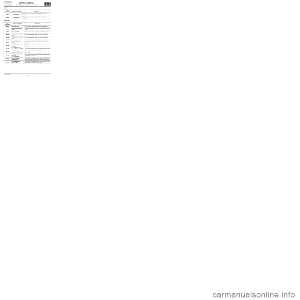
CLEAR:
ACTIVATION:Tool
commandDiagnostic tool title Comments
RZ001 Fault memoryThis command is used for clearing the stored faults from the
computer.
RZ005 programmingThis command enables you to reinitialise the entire vehicle
configuration.
Tool
commandDiagnostic tool title Comments
AC015 Fuel pump relayThis commands enables the fuel pump to be listened to.
AC017Canister bleed solenoid
valveThis command enables the canister bleed solenoid valve to be
opened.
AC027 Motorised throttleThis command enables the motorised throttle to be opened.
AC038Low speed fan assembly
relayThis command enables the fan unit relay to be controlled.
AC039High speed fan assembly
relayThis command enables the fan unit relay to be controlled.
AC079 Actuator static testThis activation enables several actuators to be controlled.
AC117Upstream O2 sensor
heatingThis command enables the upstream sensor heating to be
controlled.
AC118Downstream O2 sensor
heatingThis command enables the downstream sensor heating to be
controlled.
AC156Camshaft dephaser 1
(only for CLIO III or MODUS)This activation enables the camshaft dephaser to be controlled.
AC180Air conditioning
compressor relay controlThis command enables the air conditioning compressor relay to
be controlled.
AC199Controlled coolant
thermostat
(only for Vdiag 4C)The activation of this command enables the controlled coolant
thermostat to be opened.
AC253Camshaft dephaser:
Normal controlThis activation enables the camshaft dephaser solenoid valve to
be fully controlled in a repetitive manner with the ignition on.
AC254Camshaft dephaser:
On/off controlThis activation enables the camshaft to be completely shifted in
relation to the pulley with the engine idling.
PETROL INJECTION
Fault finding – Command summary table
Page 329 of 348
17B-329V7 MR-413-X44-17B000$190.mif
17B
SIM 32 Injection
Program no.: D3
Vdiag No.: 44, 4C, 50
and 54
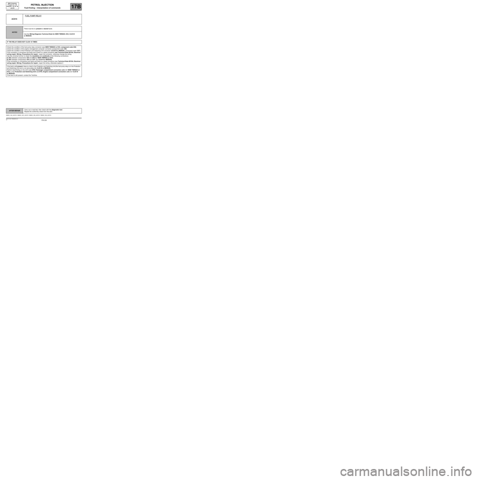
AC015FUEL PUMP RELAY
NOTESThere must be no present or stored faults.
Use the Wiring Diagrams Technical Note for NEW TWINGO, E33, CLIO III
or MODUS.
IF THE RELAY DOES NOT CLICK 10 TIMES
Check the condition of the fuel pump relay connector (see NEW TWINGO or E33, component code 236).
Check the condition of the engine management computer connector (component code 120).
Check the condition of the Protection and Switching Unit connector (CLIO III or MODUS, component code 1337).
If the connector or connectors are faulty and if there is a repair procedure (see Technical Note 6015A, Electrical
wiring repair, Wiring: Precautions for repair), repair the connector, otherwise change the wiring.
Use the universal bornier to check the insulation and continuity of the following connections:
●3AC between components 120 and 236 (for NEW TWINGO or E33),
●3AC between components 120 and 1337 (for CLIO III or MODUS).
If the connection or connections are faulty and there is a repair procedure (see Technical Note 6015A, Electrical
wiring repair, Wiring: Precautions for repair), repair the wiring, otherwise replace it.
If the fault is still present, there is a fault in the Protection and Switching Unit (the fuel pump relay is in the Protection
and Switching Unit and is not removable) (for CLIO III or MODUS).
Perform fault finding on the UCH (see 87B, Passenger compartment connection unit) (for NEW TWINGO or
E33) or the Protection and Switching Unit (see 87G, Engine compartment connection unit) (for CLIO III
or MODUS).
If the fault is still present, contact the Techline.
SIM32_V44_AC015 / SIM32_V4C_AC015 / SIM32_V50_AC015 / SIM32_V54_AC015
PETROL INJECTION
Fault finding – Interpretation of commands
AFTER REPAIRCarry out a road test, then check with the diagnostic tool.
Repeat the conformity check from the start.
Page 331 of 348
17B-331V7 MR-413-X44-17B000$190.mif
PETROL INJECTION
Fault finding – Interpretation of commands17B
SIM 32 Injection
Program no.: D3
Vdiag No.: 44, 4C, 50
and 54
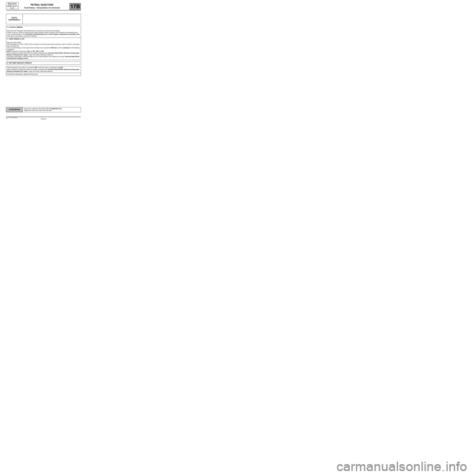
AC015
CONTINUED 2
For CLIO III or MODUS:
Reconnect the Protection and Switching Unit connector and reconnect the battery.
If there is still no + 12 V on the fuel pump relay connector, there is a fault in the Protection and Switching Unit.
Carry out fault finding on the Protection and Switching Unit (see 87G, Engine compartment connection unit).
If the fault is still present, contact the Techline.
For NEW TWINGO or E33:
Reconnect the battery.
With the ignition on, if the + 12 V is still not present on the fuel pump relay connector, there is a fault in the engine
fuse and relay box.
Carry out fault finding on the engine fuse and relay box to check the 30A fuse and the continuity of the following
connection:
●BP17 between components 120 and 397, 238 and 397.
If the connection is faulty and if there is a repair procedure (see Technical Note 6015A, Electrical wiring repair,
Wiring: Precautions for repair), repair the wiring, otherwise replace it.
If the fault is still present, check the battery and run fault finding on the charging circuit (see Technical Note 6014A,
Checking the charging circuit).
IF THE PUMP DOES NOT OPERATE
Check that there is an earth on connection MF on the fuel pump, component code 833.
If the connection is faulty and if there is a repair procedure (see Technical Note 6015A, Electrical wiring repair,
Wiring: Precautions for repair), repair the wiring, otherwise replace it.
If the fault is still present, replace the fuel pump.
AFTER REPAIRCarry out a road test, then check with the diagnostic tool.
Repeat the conformity check from the start.