engine RENAULT TWINGO 2009 2.G Electrical Equipment - Petrol Injection Workshop Manual
[x] Cancel search | Manufacturer: RENAULT, Model Year: 2009, Model line: TWINGO, Model: RENAULT TWINGO 2009 2.GPages: 348
Page 333 of 348
17B-333V7 MR-413-X44-17B000$190.mif
PETROL INJECTION
Fault finding – Interpretation of commands17B
SIM 32 Injection
Program no.: D3
Vdiag No.: 44, 4C, 50
and 54
AC017
CONTINUED
For CLIO III or MODUS:
Reconnect the Protection and Switching Unit connector and reconnect the battery.
If, with the ignition on, there is still no + 12 V on the fuel vapour absorber
canister bleed solenoid valve connector, there is a fault in the Protection and Switching Unit.
Carry out fault finding on the UPC (see 87G, Engine compartment connection unit).
If the fault is still present, contact the Techline.
For NEW TWINGO or E33:
Reconnect the injection locking relay connector and reconnect the battery.
With the ignition on, if there is still not + 12V on the connector for the fuel vapour absorber bleed solenoid, there is
a fault in the engine fuse and relay box.
Carry out fault finding on the engine fuse and relay box, by checking the continuity of the following connection:
●BP17 between components 120 and 397, 238 and 397.
If the connection is faulty and if there is a repair procedure (see Technical Note 6015A, Electrical wiring repair,
Wiring: Precautions for repair), repair the wiring, otherwise replace it.
If the fault is still present, check the battery and run fault finding on the charging circuit (see Technical Note 6014A,
Checking the charging circuit).
Disconnect the battery.
Check the condition of the engine management computer connector (see Wiring Diagrams Technical Note for
NEW TWINGO, E33, CLIO III, or MODUS, component code 120).
If the connectors are faulty and if there is a repair procedure (see Technical Note 6015A, Repairing electrical
wiring, Wiring: Precautions for repair), repair the connector, otherwise replace the wiring.
Use the universal bornier to check the insulation and continuity of the following connection:
●3BB between components 120 and 371.
If the connection is faulty and if there is a repair procedure (see Technical Note 6015A, Electrical wiring repair,
Wiring: Precautions for repair), repair the wiring, otherwise replace it.
Check for earth on connection 3BB of the fuel vapour absorber bleed solenoid valve when running command
AC017 Canister bleed solenoid valve.
Replace the fuel vapour absorber bleed solenoid valve.
If the fault is still present, contact the Techline.
AFTER REPAIRCarry out a road test, then check with the diagnostic tool.
Repeat the conformity check from the start.
Page 337 of 348
17B-337V7 MR-413-X44-17B000$190.mif
PETROL INJECTION
Fault finding – Interpretation of commands17B
SIM 32 Injection
Program no.: D3
Vdiag No.: 44, 4C, 50
and 54
AC180AIR CONDITIONING COMPRESSOR RELAY CONTROL
NOTESSpecial notes:
There must be no present or stored faults.
Use the Wiring Diagrams Technical Note for NEW TWINGO, E33, CLIO III
or MODUS.
Check the condition of the connectors of the air conditioning compressor clutch relay (component code 584) and
of the engine management computer (component code 120).
If the connector or connectors are faulty and there is a repair procedure (see Technical Note 6015A, Electrical
wiring repair, Wiring: Precautions for repair), repair the connector, otherwise replace the wiring.
With the ignition, check for + 12 V on connection 3FB of the air conditioning compressor clutch relay and the
earthing of connection 38K on the injection computer connector.
Use the universal bornier to check the insulation and continuity of the following connections:
●3FB between components 584 and 238,
●38K between components 584 and 120.
If the connection or connections are faulty and there is a repair procedure (see Technical Note 6015A, Electrical
wiring repair, Wiring: Precautions for repair), repair the wiring, otherwise replace it.
If the control still does not operate, run a diagnostic check on the Heating system.
(see 62A, Heating, 62B, Climate control or 62C, Manual air conditioning).
SIM32_V44_AC180 / SIM32_V4C_AC180 / SIM32_V50_AC180 / SIM32_V54_AC180
AFTER REPAIRIf the throttle valve has been replaced, reinitialise the RZ005 programming.
Carry out a road test, then check with the diagnostic tool.
Page 339 of 348
17B-339V7 MR-413-X44-17B000$200.mif
17B
SIM 32 Injection
Program no.: D3
Vdiag No.: 44, 4C, 50
and 54
NOTESOnly refer to the customer complaints after performing a complete check using the
diagnostic tool.
WARNING:
Never drive the vehicle without checking first that there are no throttle valve
faults.
NO DIALOGUE WITH THE COMPUTER ALP1
THE ENGINE WILL NOT START ALP2
IDLING SPEED FAULTSALP3
FAULTS WHILE DRIVINGALP4
Noise when cold (K4M)Technical
Note 6506A
ALP 1
Oil leak from the camshaft dephaser Technical
Note 6506A
ALP 7
Oil leak from the camshaft dephaser solenoid valveTechnical
Note 6506A
ALP 8
PETROL INJECTION
Fault finding – Customer complaints
Page 341 of 348
17B-341V7 MR-413-X44-17B000$210.mif
PETROL INJECTION
Fault finding – Fault Finding Chart17B
SIM 32 Injection
Program no.: D3
Vdiag No.: 44, 4C, 50
and 54
ALP1
CONTINUED 1
CHECK
ON
VEHICLE
Check the electrical voltage of the battery.
Check the cleanliness and condition of the battery terminals.
Check the condition of the battery earth cable and ensure that there is a good
electrical connection with the bodywork.
Check the condition of the engine management computer connector
(component code 120).
If the connector is faulty and there is a repair method (see Technical Note 6015A,
Repairing electrical wiring, Wiring: Precautions for repair), repair the connector,
otherwise replace the wiring.
Check the injection computer earth terminal for cleanliness and make sure it is
correctly connected to the bodywork.
Check the 30 A supply fuse of the injection locking relay, and the condition and
cleanliness of the contacts.
Check the 40 A supply fuse of the Protection and Switching Unit and the condition
and cleanliness of the contacts.
Check the injection computer after ignition feed 20 A fuse, and the condition and
cleanliness of the contacts.
AFTER REPAIRCarry out a road test, then check with the diagnostic tool.
Repeat the conformity check from the start.
Page 342 of 348
17B-342V7 MR-413-X44-17B000$210.mif
PETROL INJECTION
Fault finding – Fault Finding Chart17B
SIM 32 Injection
Program no.: D3
Vdiag No.: 44, 4C, 50
and 54
ALP1
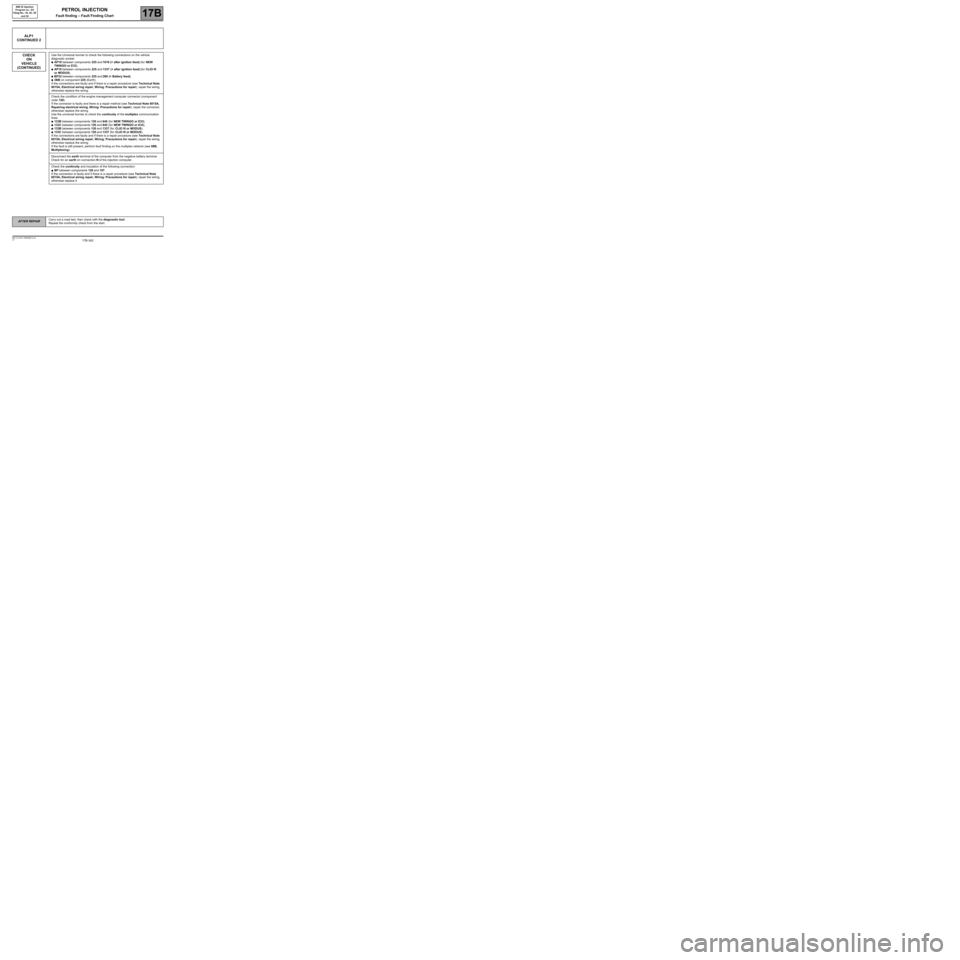
CONTINUED 2
CHECK
ON
VEHICLE
(CONTINUED)
Use the Universal bornier to check the following connections on the vehicle
diagnostic socket:
●AP10 between components 225 and 1016 (+ after ignition feed) (for NEW
TWINGO or E33),
●AP10 between components 225 and 1337 (+ after ignition feed) (for CLIO III
or MODUS),
●BP32 between components 225 and 260 (+ Battery feed),
●3BB on component 225 (Earth).
If the connections are faulty and if there is a repair procedure (see Technical Note
6015A, Electrical wiring repair, Wiring: Precautions for repair), repair the wiring,
otherwise replace the wiring.
Check the condition of the engine management computer connector (component
code 120).
If the connector is faulty and there is a repair method (see Technical Note 6015A,
Repairing electrical wiring, Wiring: Precautions for repair), repair the connector,
otherwise replace the wiring.
Use the universal bornier to check the continuity of the multiplex communication
lines:
●133B between components 120 and 645 (for NEW TWINGO or E33),
●133C between components 120 and 645 (for NEW TWINGO or E33),
●133B between components 120 and 1337 (for CLIO III or MODUS),
●133C between components 120 and 1337 (for CLIO III or MODUS).
If the connections are faulty and if there is a repair procedure (see Technical Note
6015A, Electrical wiring repair, Wiring: Precautions for repair), repair the wiring,
otherwise replace the wiring.
If the fault is still present, perform fault finding on the multiplex network (see 88B,
Multiplexing).
Disconnect the earth terminal of the computer from the negative battery terminal.
Check for an earth on connection N of the injection computer.
Check the continuity and insulation of the following connection:
●BP between components 120 and 107.
If the connection is faulty and if there is a repair procedure (see Technical Note
6015A, Electrical wiring repair, Wiring: Precautions for repair), repair the wiring,
otherwise replace it.
AFTER REPAIRCarry out a road test, then check with the diagnostic tool.
Repeat the conformity check from the start.
Page 343 of 348
17B-343V7 MR-413-X44-17B000$210.mif
PETROL INJECTION
Fault finding – Fault Finding Chart17B
SIM 32 Injection
Program no.: D3
Vdiag No.: 44, 4C, 50
and 54
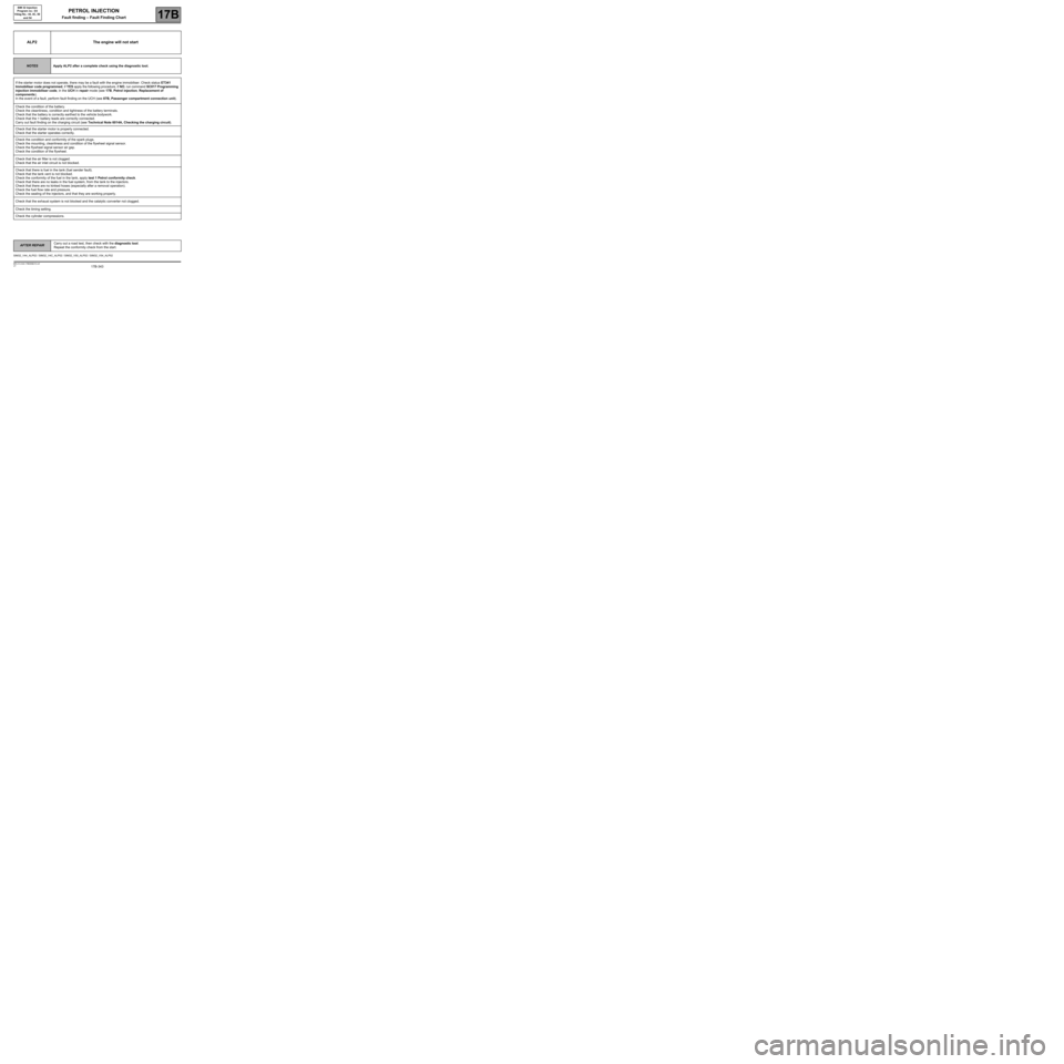
ALP2 The engine will not start
NOTESApply ALP2 after a complete check using the diagnostic tool.
If the starter motor does not operate, there may be a fault with the engine immobiliser. Check status ET341
Immobiliser code programmed, if YES apply the following procedure, if NO, run command SC017 Programming
injection immobiliser code, in the UCH in repair mode (see 17B, Petrol injection, Replacement of
components).
In the event of a fault, perform fault finding on the UCH (see 87B, Passenger compartment connection unit).
Check the condition of the battery.
Check the cleanliness, condition and tightness of the battery terminals.
Check that the battery is correctly earthed to the vehicle bodywork.
Check that the + battery leads are correctly connected.
Carry out fault finding on the charging circuit (see Technical Note 6014A, Checking the charging circuit).
Check that the starter motor is properly connected.
Check that the starter operates correctly.
Check the condition and conformity of the spark plugs.
Check the mounting, cleanliness and condition of the flywheel signal sensor.
Check the flywheel signal sensor air gap.
Check the condition of the flywheel.
Check that the air filter is not clogged.
Check that the air inlet circuit is not blocked.
Check that there is fuel in the tank (fuel sender fault).
Check that the tank vent is not blocked.
Check the conformity of the fuel in the tank, apply test 1 Petrol conformity check.
Check that there are no leaks in the fuel system, from the tank to the injectors.
Check that there are no kinked hoses (especially after a removal operation).
Check the fuel flow rate and pressure.
Check the sealing of the injectors, and that they are working properly.
Check that the exhaust system is not blocked and the catalytic converter not clogged.
Check the timing setting.
Check the cylinder compressions.
SIM32_V44_ALP02 / SIM32_V4C_ALP02 / SIM32_V50_ALP02 / SIM32_V54_ALP02
AFTER REPAIRCarry out a road test, then check with the diagnostic tool.
Repeat the conformity check from the start.
Page 347 of 348
17B-347V7 MR-413-X44-17B000$220.mif
PETROL INJECTION
Fault finding – Tests17B
SIM 32 Injection
Program no.: D3
Vdiag No.: 44, 4C, 50
and 54
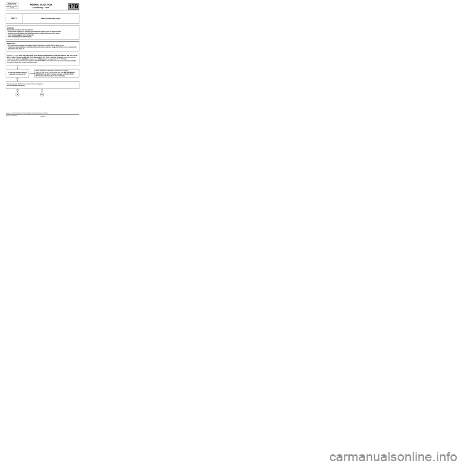
TEST 1 Petrol conformity check
WARNING
During this operation, it is essential to:
–refrain from smoking or bringing incandescent objects close to the work area,
–protect yourself against fuel splashes due to residual pressure in the pipes,
–wear safety goggles with side guards,
–wear leaktight gloves (Nitrile type).
IMPORTANT
–To avoid any corrosion or damage, protect the areas on which fuel is likely to run.
–To prevent impurities from entering the circuit, place protective plugs on all fuel circuit components
exposed to the open air.
Remove 1 l of fuel at the fuel filter outlet, in the engine compartment (see MR 385 (Modus), MR 392 (Clio III),
MR 411 (New Twingo), or MR 442 (E33), Mechanical, 19C, Tank, Fuel tank: Draining), using a pneumatic
transfer pump (part no. 634-200) and place it in 1300 ml plastic cup (part no. 77 11 171 413).
Close the plastic cup with its cover (part no. 77 11 171 416) and let the fuel rest for approximately 2 minutes.
This type of plastic cup is used to prepare paint.
Is the fuel cloudy or does it
separate into two parts?Water is present in the petrol; the fuel is not correct.
Drain the fuel circuit, including the tank (see MR 385 (Modus),
MR 392 (Clio III), MR 411 (New Twingo), or MR 442 (E33),
Mechanical, 19C Tank, Fuel tank: Draining).
Visually compare the fuel removed with the correct petrol.
Are the samples identical?
YES
NO
YES
A
NO
B
SIM32_V44_TEST1/SIM32_V4C_TEST1/SIM32_V50_TEST1/SIM32_V54_TEST1