Idle control value RENAULT TWINGO 2009 2.G Electrical Equipment - Petrol Injection Workshop Manual
[x] Cancel search | Manufacturer: RENAULT, Model Year: 2009, Model line: TWINGO, Model: RENAULT TWINGO 2009 2.GPages: 348
Page 12 of 348
17B-12V7 MR-413-X44-17B000$030.mif
PETROL INJECTION
Fault finding – System operation17B
SIM 32 Injection
Program no.: D3
Vdiag No.: 44, 4C, 50
and 54
ET086: Camshaft dephaser control
FAULT: this defect mode covers all faults that affect the measurement of the dephaser position.
The dephaser is controlled at the lower stop and the camshaft angle measurement is forced to 0.
Tooth signal fault.
Tooth/camshaft signal consistency fault finding procedure.
This type covers all faults affecting the camshaft dephaser (pulley and solenoid valve)
●Electrical fault finding on the solenoid valve.
●The camshaft dephaser is controlled at the lower stop.
FAULT: this defect mode covers all faults that affect the dephaser (pulley and solenoid valve).
The dephaser is set to the low stop.
Electrical fault finding on the solenoid valve.
Dephaser position fault finding procedure.
This type groups together all faults affecting the measuring of the camshaft dephaser position.
●tooth signal fault
●tooth/camshaft signal consistency fault finding procedure
The VVT is controlled at the lower stop and the camshaft angle measurement is forced to the requested setpoint.
A first program called Memo phasing is applied to phase the engine management on starting according to the data
recorded at the last setting. It is therefore essential to wait until the end of the "powerlatch" phase (computer self-
supply phase enabling data to be saved which lasts for approximately 30 seconds) before starting any operations.
Then, a second program confirms the first decision. It is based on torque analysis.
Air supply
The idle speed regulator performs all of the calculations required for physical control of the idle speed actuator: the
motorised throttle. The functional component of the regulator is adaptive (variation programming and ageing).
If the idle speed regulation conditions are met, the status ET054 Idle speed regulation is "Active", and the idle
speed regulator continually positions the motorised throttle to maintain the engine speed at its idle reference value.
The motorised throttle opening ratio necessary to comply with the speed setpoint is then given by parameter
PR091 Idle speed regulation theoretical OCR.
The PR090 Idle speed regulation programming value is a stored parameter designed to "program" engine
variations and engine wear and tear for the idle speed regulator. The programming is carried out only when the
engine is idle and warm, and no electrical consumer (air conditioning, fan assembly, power assisted steering) is
operating. Therefore it adjusts slowly.
Page 13 of 348
17B-13V7 MR-413-X44-17B000$030.mif
PETROL INJECTION
Fault finding – System operation17B
SIM 32 Injection
Program no.: D3
Vdiag No.: 44, 4C, 50
and 54
Idle speed
The idle speed setpoint is dependent on:
–the coolant temperature,
–the emission control programs,
–air conditioning requirements,
–the position of the gear lever,
–any power-assisted steering operation,
–the passenger compartment heating resistors,
–the oil temperature (engine protection),
–and lastly, the electric power balance (engine speed is increased by a maximum of 160 rpm if the battery voltage
remains below 12.7 V).
Ignition
Advance is calculated for each cylinder, and is limited between - 23˚ to + 72˚, and includes possible corrections due
to pinking.
Anti-pinking correction is the maximum advance value taken from the advance of one of the cylinders. If none of the
cylinders is pinking, this correction is zero.
Richness
For the catalytic converter to operate correctly, adjust around richness 1.
The richness regulation controlled by the upstream sensor which ensures a richness of around 1.
The upstream sensor supplies a voltage according to the image of the average engine richness: the voltage supplied
to the computer represents a Rich-Lean signal.
For the upstream sensor to be operational very rapidly, it is heated. The heating works only when the engine is
running. It is deactivated at speeds above 84 mph (140 km/h) or when the engine is under load.
The downstream sensor is also heated. The command does not activate immediately after starting the engine. It is
activated when the engine is running and has reached its operating temperature. The downstream heating sensor is
deactivated at speeds above 84 mph (140 km/h) or when the engine is under load.
Torque management
The torque structure is the system for managing engine torque. It is required for certain functions such as the
electronic stability program (ESP), automatic transmission (BVA) or sequential gearbox (BVR).
Each computer (ESP, sequential gearbox, automatic transmission) sends a request for torque via the multiplex
network to the injection computer. This intervenes between the torque requests received and the driver's requests
(made via the pedal or the cruise control/speed limiter function). The result of this intervention is the torque setpoint
to be applied. Using the torque setpoint, the structure calculates the throttle position setpoint, the ignition advance
and if the turbocharging function is present, the turbocharging solenoid valve setpoint.
Page 24 of 348
17B-24V7 MR-413-X44-17B000$060.mif
PETROL INJECTION
Fault finding – Features17B
SIM 32 Injection
Program no.: D3
Vdiag No.: 44, 4C, 50
and 54
Air supply
The idle speed regulator performs all of the calculations that allow the idle speed actuator, the motorised throttle, to
be controlled physically. The functional component of the regulator is adaptive (variation programming and ageing).
If the idle speed regulation conditions are met, the status ET054 Idle speed regulation is "Active", and the idle
speed regulator continually positions the motorised throttle to maintain the engine speed at its idle reference value.
The motorised throttle opening ratio necessary to comply with the speed setpoint is then given by parameter PR091
Idle speed regulation theoretical OCR*.
The PR090 Idle speed regulation programming value is a stored parameter designed to program engine
variations and engine wear and tear for the idle speed regulator. The programming is carried out only when the
engine is idle and warm, and no electrical consumer (air conditioning, fan assembly, power assisted steering) is
operating. Therefore it adjusts slowly.
Idle speed
The idle speed setpoint is dependent on:
–the coolant temperature,
–the emission control programs,
–air conditioning requirements,
–the position of the gear lever,
–any power-assisted steering operation,
–the passenger compartment heating resistors,
–the oil temperature (engine protection),
–the electric power balance (engine speed is increased by 160 rpm maximum if the battery voltage remains below
12.7 V).
Ignition
Advance is calculated for each cylinder, and is limited between - 23˚ to + 72˚, and includes possible corrections due
to pinking.
Anti-pinking correction is the maximum advance value taken from the advance of one of the cylinders. If none of the
cylinders is pinking, this correction is zero.
Page 264 of 348
17B-264V7 MR-413-X44-17B000$160.mif
PETROL INJECTION
Fault finding – Parameter summary table17B
SIM 32 Injection
Program no.: D3
Vdiag No.: 44, 4C, 50
and 54
OCR*: Opening cyclic ratio
Heat.*: Heating
Tool ParameterDiagnostic tool title
PR125Power consumed by the air conditioning compressor
PR126Advance after anti-pinking correction
PR127Heat.* resistor maximum authorised power
PR130Cruise control setpoint
PR138Richness correction
PR143Self-adapting richness gain
PR144Self-adapting richness offset
PR147Pedal potentiometer voltage gang 1
PR148Pedal potentiometer voltage gang 2
PR190Engine idle speed setpoint.
PR312Inlet manifold vacuum
PR424Programming the no-load position value
PR427Average pinking signal
PR429Measured throttle position
PR448Ignition advance
PR538Measured throttle voltage, gang 2
PR539Measured throttle voltage gang 1
PR568Pedal position gang 1
PR569Pedal position gang 2
PR587Motorised throttle lower stop gang 1
PR588Motorised throttle lower stop gang 2
PR589Motorised throttle upper stop gang 1
PR590Motorised throttle upper stop gang 2
PR632Controlled coolant thermostat OCR* (Vdiag 4C only)
PR743Estimated alcohol level in the tank (CLIO III or MODUS only)
PR744Engine temperature setpoint (Vdiag 4C only)
PR745Camshaft dephaser position setpoint (Vdiag 4C only)
PR746Camshaft dephaser position (Vdiag 4C only)
PR873Oil oxidation signal (except D7F800 and D4F772)
PR874Last overhaul (except D7F800 and D4F772)
PR926Alcohol fuel adaptive correction (CLIO III or MODUS only)
Page 265 of 348
17B-265V7 MR-413-X44-17B000$171.mif
17B
SIM 32 Injection
Program no.: D3
Vdiag No.: 44, 4C, 50
and 54
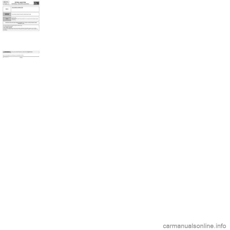
PR014IDLE SPEED CORRECTION
PARAMETER
DEFINITIONThis parameter indicates the engine's rotational speed in rpm.
NOTESSpecial notes:
Only perform these tests if the parameters do not correspond with the system operation
programming.
Conformity check with engine stopped and ignition on, or engine running and engine coolant
temperature > 80˚C
This status indicates the engine idle speed correction value.
The value should be between:
0 rpm < PR014 < 224 rpm.
The idle speed regulator performs all of the calculations that allow the idle speed actuator to be controlled
physically: the motorised throttle. The functional component of the regulator is adaptive (variation programming
and ageing).
SIM32_V44_PR014/SIM32_V4C_PR014/SIM32_V50_PR014/SIM32_V54_PR014
PETROL INJECTION
Fault finding – Interpretation of parameters
AFTER REPAIRCarry out a road test followed by a check with the diagnostic tool.