wiring RENAULT TWINGO 2009 2.G Electrical Equipment - Radio R2-08 Workshop Manual
[x] Cancel search | Manufacturer: RENAULT, Model Year: 2009, Model line: TWINGO, Model: RENAULT TWINGO 2009 2.GPages: 106, PDF Size: 0.61 MB
Page 2 of 106
86A-2V1 MR-413-X44-86A150$010.mif
86A
R2-08
Vdiag No.: 64
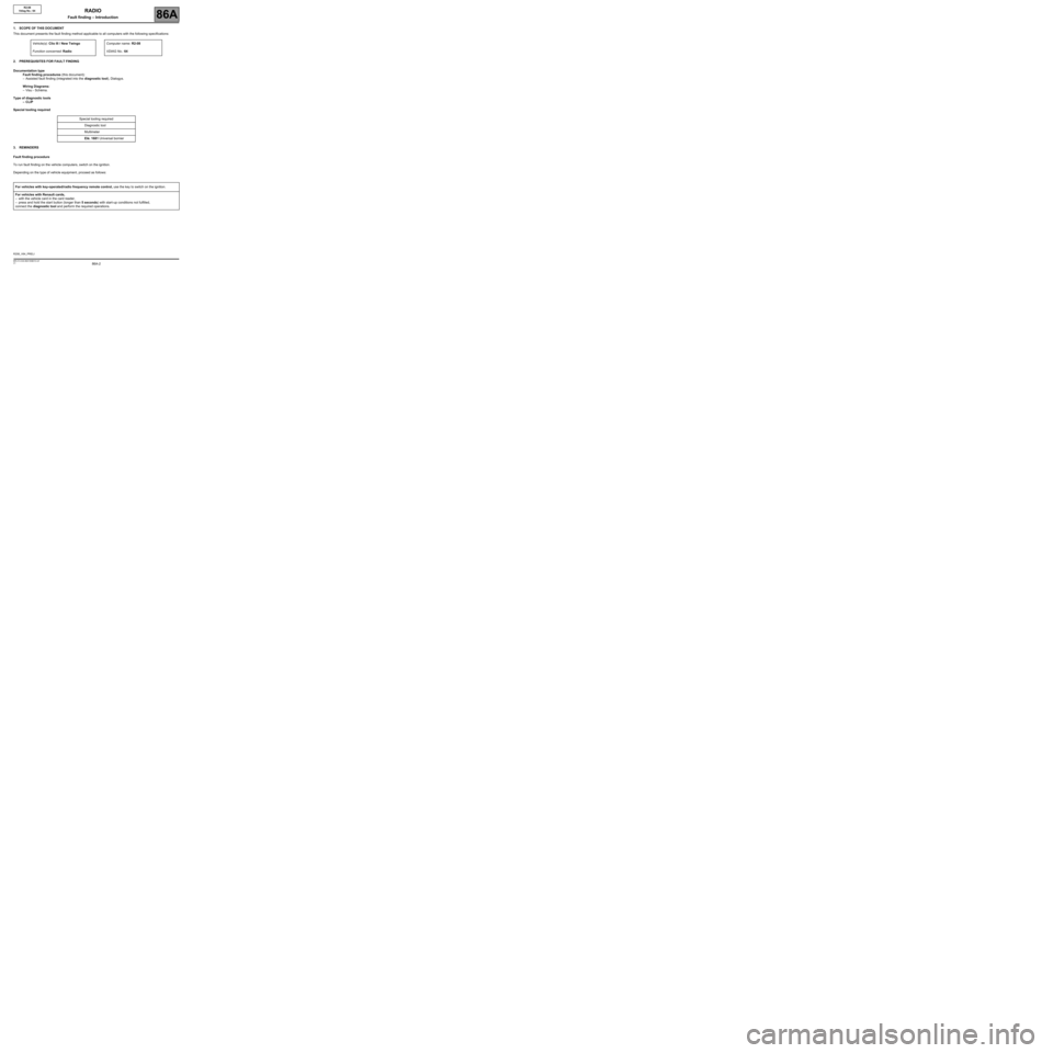
1. SCOPE OF THIS DOCUMENT
This document presents the fault finding method applicable to all computers with the following specifications:
2. PREREQUISITES FOR FAULT FINDING
Documentation type
Fault finding procedures (this document):
–Assisted fault finding (integrated into the diagnostic tool), Dialogys.
Wiring Diagrams:
–Visu - Schéma.
Type of diagnostic tools
–CLIP
Special tooling required
3. REMINDERS
Fault finding procedure
To run fault finding on the vehicle computers, switch on the ignition.
Depending on the type of vehicle equipment, proceed as follows:Vehicle(s): Clio III / New TwingoComputer name: R2-08
Function concerned: RadioVDIAG No.: 64
Special tooling required
Diagnostic tool
Multimeter
Elé. 1681 Universal bornier
For vehicles with key-operated/radio frequency remote control, use the key to switch on the ignition.
For vehicles with Renault cards,
–with the vehicle card in the card reader,
–press and hold the start button (longer than 5 seconds) with start-up conditions not fulfilled,
connect the diagnostic tool and perform the required operations.
R208_V64_PRELI
RADIO
Fault finding – Introduction
Page 6 of 106

86A-6V1 MR-413-X44-86A150$010.mif
RADIO
Fault finding – Introduction86A
R2-08
Vdiag No.: 64
4. FAULT FINDING PROCEDURE (continued)
4.1 Wiring check
Fault finding problems
Disconnecting the connectors and/or manipulating the wiring may temporarily clear the cause of a fault.
Electrical measurements of voltage, resistance and insulation are generally correct, especially if the fault is not
present when the analysis is made (stored fault).
Visual inspection
Look for damage under the bonnet and in the passenger compartment.
Carefully check the fuses, insulators and wiring harness routing.
Look for signs of oxidation.
Physical inspection
When handling the wiring, use the diagnostic tool to detect any change in the status of the fault from stored to
present.
Make sure that the connectors are firmly secured.
Apply light pressure to the connectors.
Twist the wiring harness.
If there is a change in status, try to locate the source of the fault.
Checking earth insulation
This check is carried out by measuring the voltage (multimeter in voltmeter mode) between the suspect connection
and the 12 V or 5 V. The correct measured value is 0 V.
Checking insulation against + 12 V or + 5 V
This check is carried out by measuring the voltage (multimeter in voltmeter mode) between the suspect
connection and the earth. In the first instance, the earth may be taken on the chassis. The correct measured
value should be 0 V
Continuity check
A continuity check is carried out by measuring the resistance (multimeter in ohmmeter mode), with the connectors
disconnected at both ends. The expected result must be between: 0 Ω < X < 2 Ω for every connection. The line must
be fully checked, and the intermediate connections are only included in the method if this saves time during the fault
finding procedure. The continuity check on the multiplex lines must be carried out on both wires. The measured
value must be between: 0 Ω < X < 2 Ω.
Checking the supply
This check may be carried out using a test light (21 W or 5 W depending on the maximum authorised load)
Page 8 of 106
86A-8V1 MR-413-X44-86A150$010.mif
RADIO
Fault finding – Introduction86A
R2-08
Vdiag No.: 64
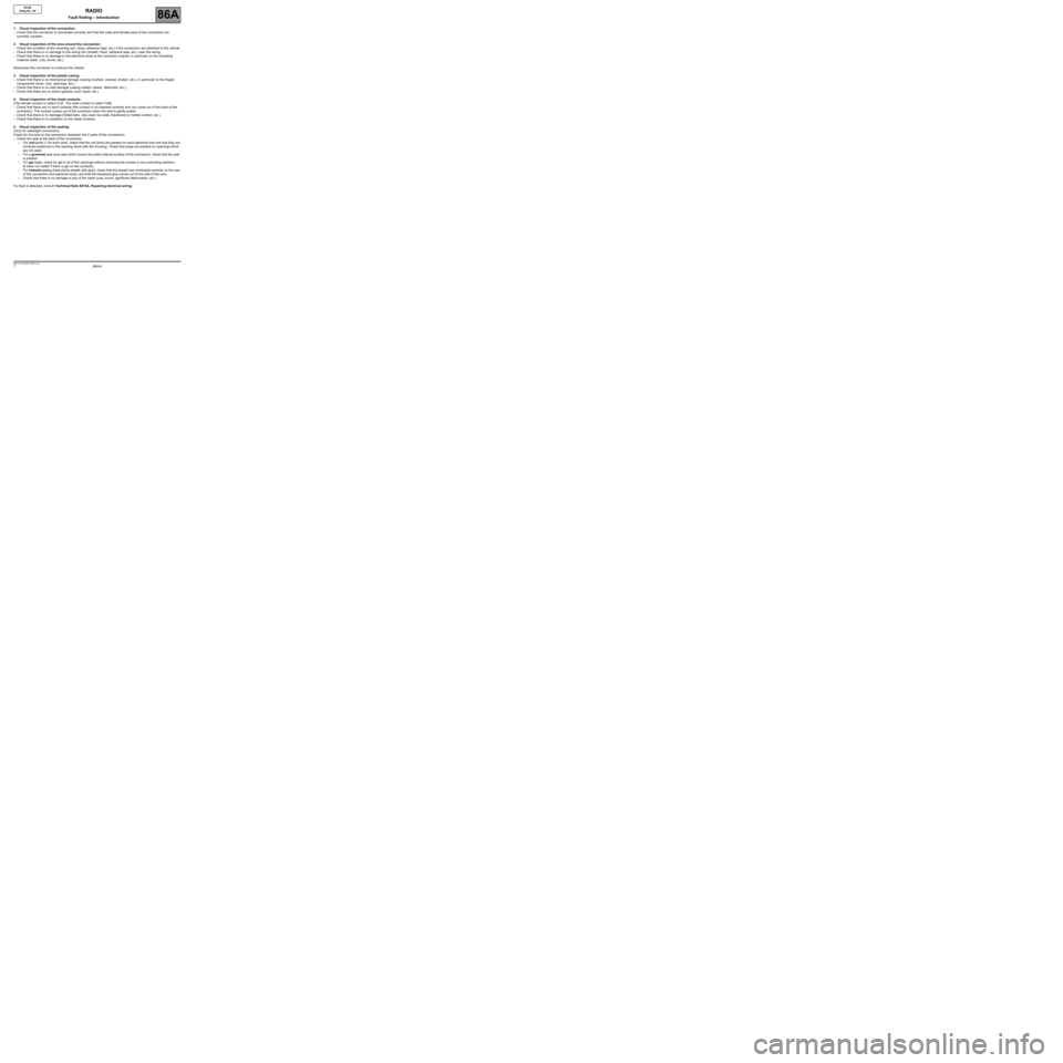
1. Visual inspection of the connection:
–Check that the connector is connected correctly and that the male and female parts of the connection are
correctly coupled.
2. Visual inspection of the area around the connection:
–Check the condition of the mounting (pin, strap, adhesive tape, etc.) if the connectors are attached to the vehicle.
–Check that there is no damage to the wiring trim (sheath, foam, adhesive tape, etc.) near the wiring.
–Check that there is no damage to the electrical wires at the connector outputs, in particular on the insulating
material (wear, cuts, burns, etc.).
Disconnect the connector to continue the checks.
3. Visual inspection of the plastic casing:
–Check that there is no mechanical damage (casing crushed, cracked, broken, etc.), in particular to the fragile
components (lever, lock, openings, etc.).
–Check that there is no heat damage (casing melted, darker, deformed, etc.).
–Check that there are no stains (grease, mud, liquid, etc.).
4. Visual inspection of the metal contacts:
(The female contact is called CLIP. The male contact is called TAB).
–Check that there are no bent contacts (the contact is not inserted correctly and can come out of the back of the
connector). The contact comes out of the connector when the wire is gently pulled.
–Check that there is no damage (folded tabs, clips open too wide, blackened or melted contact, etc.).
–Check that there is no oxidation on the metal contacts.
5. Visual inspection of the sealing:
(Only for watertight connectors)
Check for the seal on the connection (between the 2 parts of the connection).
–Check the seal at the back of the connectors:
–For unit joints (1 for each wire), check that the unit joints are present on each electrical wire and that they are
correctly positioned in the opening (level with the housing). Check that plugs are present on openings which
are not used.
–For a grommet seal (one seal which covers the entire internal surface of the connector), check that the seal
is present.
–For gel seals, check for gel in all of the openings without removing the excess or any protruding sections
(it does not matter if there is gel on the contacts).
–For hotmelt sealing (heat-shrink sheath with glue), check that the sheath has contracted correctly on the rear
of the connectors and electrical wires, and that the hardened glue comes out of the side of the wire.
–Check that there is no damage to any of the seals (cuts, burns, significant deformation, etc.).
If a fault is detected, consult Technical Note 6015A, Repairing electrical wiring.
Page 33 of 106
86A-33
AFTER REPAIRCarry out another fault finding check on the system.
Clear the stored faults using command RZ003 Fault memory.
Deal with any other faults.
V1 MR-413-X44-86A150$120.mif
86A
R2-08
Vdiag No.: 64
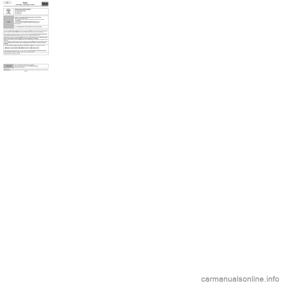
DF001
PRESENT
OR
STOREDFRONT RIGHT-HAND SPEAKERCC.0: Short circuit to earth
CC.1: Short circuit to + 12 V
CO: Open circuit
CC: Short circuit
NOTESConditions for applying fault finding procedures to stored faults:
The fault is declared present after:
–The multimedia system was switched on using the on/off button for at least
10 seconds,
–Command AC004 Front right-hand speakers line test was run.
–The fault can only be detected if the battery voltage is between:
12 V < X < 15 V.
Use the Wiring Diagrams Technical Note for Clio III or New Twingo.
Check the condition and connection of the connectors of the radio 261, of the front right-hand tweeter 365, of
the front right-hand speaker 1598 (left-hand drive) or 1597 (right-hand drive) (bent or broken tabs, etc.).
If the connector(s) is faulty and if there is a repair procedure (see Technical Note 6015A, Repairing electrical
wiring, Wiring: Precautions for repair), repair the connector, otherwise replace the wiring.
Disconnect the connector of component 1598 (left-hand drive) or 1597 (right-hand drive) (see MR 392 (Clio III) or
MR 411 (New Twingo) Mechanical, 86A, Radio, Front speaker: Removal - Refitting).
Measure the resistance of component 1598 (left-hand drive) or 1597 (right-hand drive) using a multimeter, with the
ignition off.
If the resistance is not between: 3.5 Ω < X < 4.5 Ω, replace component 1598 (left-hand drive) or 1597 (right-hand
drive) (see MR 392 (Clio III) or MR 411 (New Twingo) Mechanical, 86A, Radio, Front speaker: Removal -
Refitting).
Check the continuity, insulation and absence of interference resistance on the following connections:
•34E between components 261 and 365, 1598 (left-hand drive) or 1597 (right-hand drive),
•34F between components 261 and 365, 1598 (left-hand drive) or 1597 (right-hand drive).
If the connection(s) are faulty and there is a repair method (see Technical Note 6015A, Repairing electrical
wiring, Wiring: Precautions for repair), repair the wiring, otherwise replace it.
If the fault persists, contact your Techline.
R208_V64_DF001
RADIO
Fault finding – Interpretation of faults
Page 34 of 106
86A-34
AFTER REPAIRCarry out another fault finding check on the system.
Clear the stored faults using command RZ003 Fault memory.
Deal with any other faults.
V1 MR-413-X44-86A150$120.mif
RADIO
Fault finding – Interpretation of faults86A
R2-08
Vdiag No.: 64
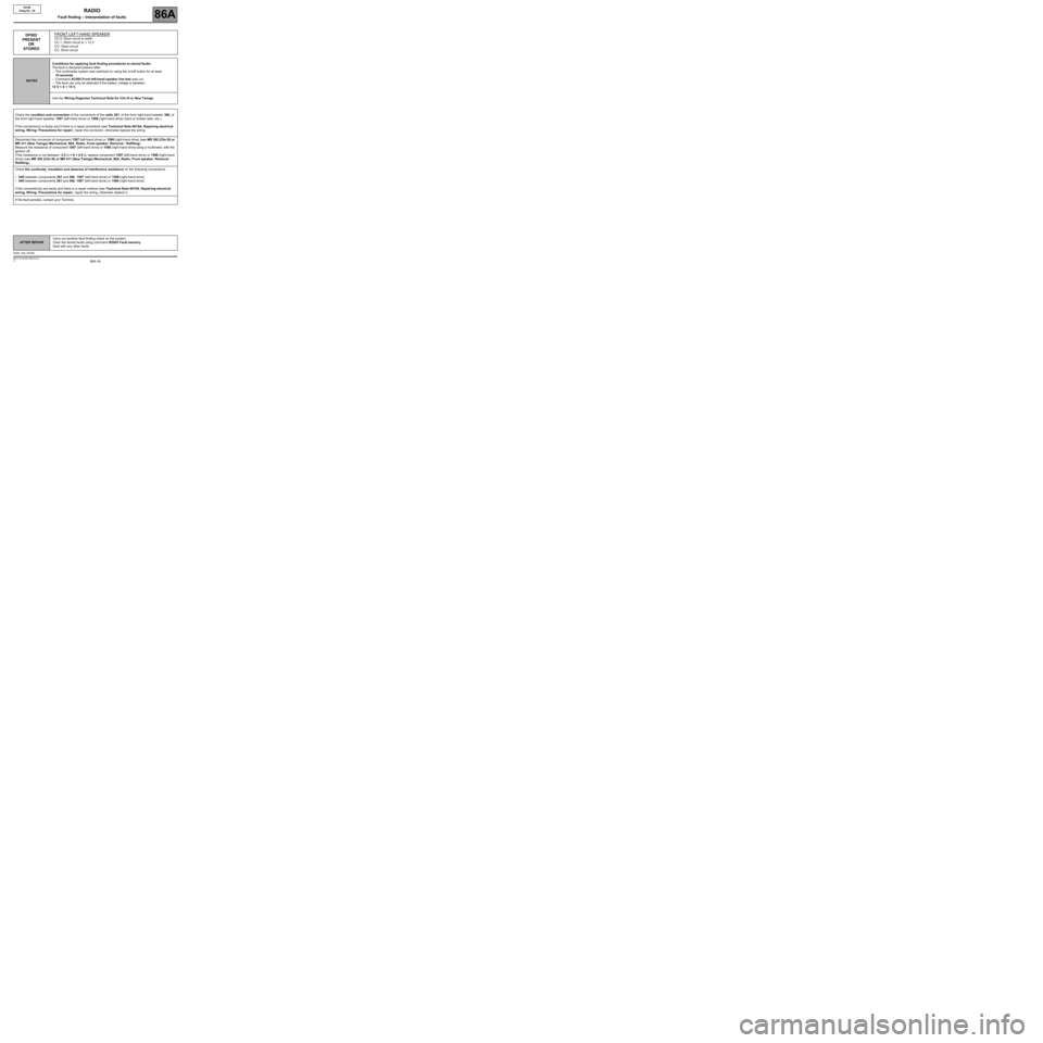
DF002
PRESENT
OR
STOREDFRONT LEFT-HAND SPEAKERCC.0: Short circuit to earth
CC.1: Short circuit to + 12 V
CO: Open circuit
CC: Short circuit
NOTESConditions for applying fault finding procedures to stored faults:
The fault is declared present after:
–The multimedia system was switched on using the on/off button for at least
10 seconds,
–Command AC005 Front left-hand speaker line test was run,
–The fault can only be detected if the battery voltage is between:
12 V < X < 15 V.
Use the Wiring Diagrams Technical Note for Clio III or New Twingo.
Check the condition and connection of the connectors of the radio 261, of the front right-hand tweeter 366, of
the front right-hand speaker 1597 (left-hand drive) or 1598 (right-hand drive) (bent or broken tabs, etc.).
If the connector(s) is faulty and if there is a repair procedure (see Technical Note 6015A, Repairing electrical
wiring, Wiring: Precautions for repair), repair the connector, otherwise replace the wiring.
Disconnect the connector of component 1597 (left-hand drive) or 1598 (right-hand drive) (see MR 392 (Clio III) or
MR 411 (New Twingo) Mechanical, 86A, Radio, Front speaker: Removal - Refitting).
Measure the resistance of component 1597 (left-hand drive) or 1598 (right-hand drive) using a multimeter, with the
ignition off.
If the resistance is not between: 3.5 Ω < X < 4.5 Ω, replace component 1597 (left-hand drive) or 1598 (right-hand
drive) (see MR 392 (Clio III) or MR 411 (New Twingo) Mechanical, 86A, Radio, Front speaker: Removal -
Refitting).
Check the continuity, insulation and absence of interference resistance on the following connections:
•34G between components 261 and 366, 1597 (left-hand drive) or 1598 (right-hand drive),
•34H between components 261 and 366, 1597 (left-hand drive) or 1598 (right-hand drive).
If the connection(s) are faulty and there is a repair method (see Technical Note 6015A, Repairing electrical
wiring, Wiring: Precautions for repair), repair the wiring, otherwise replace it.
If the fault persists, contact your Techline.
R208_V64_DF002
Page 35 of 106
86A-35
AFTER REPAIRCarry out another fault finding check on the system.
Clear the stored faults using command RZ003 Fault memory.
Deal with any other faults.
V1 MR-413-X44-86A150$120.mif
RADIO
Fault finding – Interpretation of faults86A
R2-08
Vdiag No.: 64
DF003
PRESENT
OR
STOREDREAR RIGHT-HAND SPEAKERCC.0: Short circuit to earth
CC.1: Short circuit to + 12 V
CO: Open circuit
CC: Short circuit
NOTESConditions for applying fault finding procedures to stored faults:
The fault is declared present after:
–The multimedia system was switched on using the on/off button for at least
10 seconds,
–Command AC006 Rear right-hand speaker line test was run,
–The fault can only be detected if the battery voltage is between:
12 V < X < 15 V.
Use the Wiring Diagrams Technical Note for Clio III or New Twingo.
Check the condition and connection of the connectors of radio 261 and of the rear right-hand speaker 189
(bent or broken tabs, etc.).
If the connector(s) is faulty and if there is a repair procedure (see Technical Note 6015A, Repairing electrical
wiring, Wiring: Precautions for repair), repair the connector, otherwise replace the wiring.
Disconnect the connector of component 189 (see MR 392 (Clio III) or MR 411 (New Twingo) Mechanical, 86A,
Radio, Rear speaker: Removal - Refitting).
Measure the resistance of component 189 using a multimeter, with the ignition off.
If the resistance is not between: 3.5 Ω < X < 4.5 Ω, replace component 189 (see MR 392 (Clio III) or MR 411
(New Twingo) Mechanical, 86A, Radio, Rear speaker: Removal - Refitting).
Check the continuity, insulation and absence of interference resistance on the following connections:
•34D between components 261 and 189,
•34C between components 261 and 189.
If the connections are faulty and if there is a repair procedure (see Technical Note 6015A, Electrical wiring
repair, Wiring: Precautions for repair), repair the wiring, otherwise replace it.
If the fault persists, contact your Techline.
R208_V64_DF003
Page 36 of 106
86A-36
AFTER REPAIRCarry out another fault finding check on the system.
Clear the stored faults using command RZ003 Fault memory.
Deal with any other faults.
V1 MR-413-X44-86A150$120.mif
RADIO
Fault finding – Interpretation of faults86A
R2-08
Vdiag No.: 64
DF004
PRESENT
OR
STOREDREAR LEFT-HAND SPEAKERCC.0: Short circuit to earth
CC.1: Short circuit to + 12 V
CO: Open circuit
CC: Short circuit
NOTESConditions for applying fault finding procedures to stored faults:
The fault is declared present after:
–The multimedia system was switched on using the on/off button for at least
10 seconds,
–Command AC007 Rear left-hand speaker line test was run,
–The fault can only be detected if the battery voltage is between:
12 V < X < 15 V.
Use the Wiring Diagrams Technical Note for Clio III or New Twingo.
Check the condition and connection of the connectors of radio 261 and of the rear left-hand speaker 190 (bent or
broken tabs, etc.).
If any of the connectors are faulty and there is a repair method (see Technical Note 6015A, Electrical wiring
repair, Wiring: Precautions for repair), repair the connector, otherwise replace the wiring.
Disconnect the connector of component 190 (see MR 392 (Clio III) or MR 411 (New Twingo) Mechanical, 86A,
Radio, Rear speaker: Removal - Refitting).
Measure the resistance of component 190 using a multimeter, with the ignition off.
If the resistance is not between: 3.5 Ω < X < 4.5 Ω, replace component 190 (see MR 392 (Clio III) or MR 411
(New Twingo) Mechanical, 86A, Radio, Rear speaker: Removal - Refitting).
Check the continuity, insulation and absence of interference resistance on the following connections:
•34A between components 261 and 190,
•34B between components 261 and 190.
If the connection(s) are faulty and there is a repair method (see Technical Note 6015A, Repairing electrical
wiring, Wiring: Precautions for repair), repair the wiring, otherwise replace it.
If the fault persists, contact your Techline.
R208_V64_DF004
Page 37 of 106
86A-37
AFTER REPAIRCarry out another fault finding check on the system.
Clear the stored faults using command RZ003 Fault memory.
Deal with any other faults.
V1 MR-413-X44-86A150$120.mif
RADIO
Fault finding – Interpretation of faults86A
R2-08
Vdiag No.: 64
DF006
PRESENT
OR
STOREDFM1 AMPLI
CC.0: Short circuit to earth
CO: Open circuit
NOTESConditions for applying fault finding procedures to stored faults:
The fault is declared present after the multimedia system is switched on using the on/
off button.
The fault can only be detected if the battery voltage is between:
12 V < X < 15 V.
Use the Wiring Diagrams Technical Note for Clio III or New Twingo.
If the vehicle is equipped with a navigation system, go on to Part B, otherwise go to Part A.
Part A:
Check the connection and condition of the aerial connectors on the radio, component code 261, and on the roof
aerial connector, component code 1208.
If the connector(s) is faulty and if there is a repair procedure (see Technical Note 6015A, Repairing electrical
wiring, Wiring: Precautions for repair), repair the connector, otherwise replace the wiring.
Check the insulation, continuity and absence of interference resistance on the following connections:
•34AN between components 261 and 1208,
•TB13 between components 261 and 1208.
If the connections are faulty and if there is a repair procedure (see Technical Note 6015A, Electrical wiring
repair, Wiring: Precautions for repair), repair the wiring, otherwise replace it.
If the connections are correct, replace the roof aerial amplifier, component code 1208 (see MR 392 (Clio III) or
MR 411 (New Twingo) Mechanical, 86A, Radio, Radio aerial: Removal - Refitting).
If the fault is still present, replace the radio (see MR 392 (Clio III) or MR 411 (New Twingo) Mechanical, 86A,
Radio, Radio: Removal - Refitting).
If the fault persists, contact your Techline.
R208_V64_DF006
Page 38 of 106
86A-38
AFTER REPAIRCarry out another fault finding check on the system.
Clear the stored faults using command RZ003 Fault memory.
Deal with any other faults.
V1 MR-413-X44-86A150$120.mif
RADIO
Fault finding – Interpretation of faults86A
R2-08
Vdiag No.: 64
DF006
CONTINUED
Part B:
Check the connection and condition of the aerial connectors on the radio and navigation system, component codes
261 and 662, and of the connector on the roof aerial, component code 1874.
If the connector(s) is faulty and if there is a repair procedure (see Technical Note 6015A, Repairing electrical
wiring, Wiring: Precautions for repair), repair the connector, otherwise replace the wiring.
Check the insulation, continuity and absence of interference resistance on the following connections:
•46CJ between components 261 and 662,
•TB82 between components 261 and 662.
If the connection(s) are faulty and there is a repair method (see Technical Note 6015A, Repairing electrical
wiring, Wiring: Precautions for repair), repair the wiring, otherwise replace it.
Check the insulation, continuity and absence of interference resistance on the following connections:
•34EP between components 261 and 1874,
•TB39 between components 261 and 1874.
If the connection(s) are faulty and there is a repair method (see Technical Note 6015A, Repairing electrical
wiring, Wiring: Precautions for repair), repair the wiring, otherwise replace it.
If the connections are correct, replace the roof aerial amplifier, component code 1874 (see MR 392, Mechanical,
86A, Radio, Radio aerial: Removal - Refitting).
If the fault is still present, replace the radio (see MR 392, Mechanical, 86A, Radio, Radio: Removal - Refitting).
If the fault persists, contact your Techline.
Page 40 of 106
86A-40
AFTER REPAIRCarry out another fault finding check on the system.
Clear the stored faults using command RZ003 Fault memory.
Deal with any other faults.
V1 MR-413-X44-86A150$120.mif
RADIO
Fault finding – Interpretation of faults86A
R2-08
Vdiag No.: 64
DF023
PRESENT
OR
STOREDCD CHANGER
1.DEF: Internal electronic fault
NOTESAn ACB (Audio Connection Unit) can also be connected in place of the CD changer.
Use the Wiring Diagrams Technical Note for Clio III or New Twingo.
Check for a CD changer in the vehicle.
Check the consistency between the configuration of the radio and the vehicle equipment by reading configuration
LC005 External components and correct it, if necessary, using SC002 Computer configuration
(see Configuration and programming).
If the vehicle is equipped with a CD changer, it was fitted as an accessory. Please refer to the handbook delivered
with the product.
If the fault is still present, replace the CD changer.
R208_V64_DF023