RENAULT TWINGO 2009 2.G Electrical Equipment - Radio Owner's Manual
Manufacturer: RENAULT, Model Year: 2009, Model line: TWINGO, Model: RENAULT TWINGO 2009 2.GPages: 42, PDF Size: 0.29 MB
Page 21 of 42

86A-21
MR-413-X44-86A000$819_eng.mif
V1
RADIO
Fault finding chart86A
ALP 3
CONTINUED
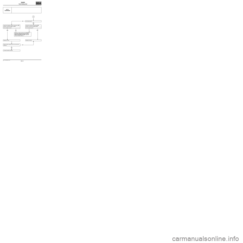
Check the insulation to earth of connection SP2
between components 261 and 1016.
Is the insulation correct?
YES NO
Replace the fuse.
Does the radio operate after the fuse has been
replaced?
YES
The fault has been rectified.
NOIs the fuse sound?
YES
Check the continuity of connection SP2
between components 1016 and 261.
Is the continuity good?
YES
Replace the radio.
If there is a repair procedure (see Technical
Note 6015A, Repairing electrical wiring,
Wiring: Precautions for repair), repair the
wiring, otherwise replace it.
NOA
Page 22 of 42

86A-22
MR-413-X44-86A000$819_eng.mif
V1
RADIO
Fault finding chart86A
ALP 4The radio is switched on, but the display and control satellite do
not operate
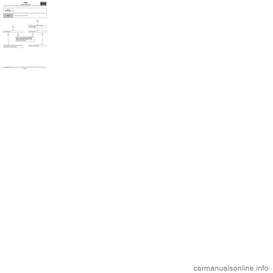
NOTESFor radio versions with remote display.
The radio operates but the display does not
light up.
Check the functions of the display that are not
connected to the radio by switching on the “+
side lights feed” (screen backlighting and
exterior temperature).
Does the backlighting or exterior temperature
display work?
YES
Check the continuity and insulation of the wiring
between the radio and the display using a
multimeter (see Wiring Diagrams Technical
Note for New Twingo, code 261).
NODisconnect the aerial amplifier
(component 886).
Does the screen light up?
YES NO
C
BA
Page 23 of 42

86A-23
MR-413-X44-86A000$819_eng.mif
V1
RADIO
Fault finding chart86A
ALP 4
CONTINUED 1
NOTESFor radio versions with remote display.
Are the tests OK?
YES NO
Disconnect then reconnect the display. If the fault
is still present, replace the display.
Check the continuity and insulation of
connection 34AM.
Are the tests OK?
NO YES
Replace the aerial amplifier.
If there is a repair procedure (see Technical
Note 6015A, Repairing electrical wiring,
Wiring: Precautions for repair), repair the
wiring, otherwise replace it.
B
C
Page 24 of 42

86A-24
MR-413-X44-86A000$819_eng.mif
V1
RADIO
Fault finding chart86A
ALP 4
CONTINUED 2
NOTESFor radio versions with remote display.
Check for 12 V between connections BCP4 and
MAM of component 653.
Is there a voltage of 12 V?
YES
Check for 12 V on connection SP2 of
component 653.
Is there a voltage of 12 V?
NO YES
Continuity fault on connection SP2 between
components 653 and 1016. If there is a repair
procedure (see Technical Note 6015A,
Repairing electrical wiring, Wiring:
Precautions for repair), repair the wiring,
otherwise replace it.
NOCheck for 12 V between connection BCP4
and the chassis earth.
Is there a voltage of 12 V?
YES NO
Continuity fault on connection BCP4 between
components 653 and 1016. If there is a repair
procedure (see Technical Note 6015A,
Repairing electrical wiring, W iring:
Precautions for repair), repair the wiring,
otherwise replace it.
Continuity fault on the earth MAM of
component 653 on the chassis. If there is a
repair procedure (see Technical Note 6015A,
Repairing electrical wiring, Wiring:
Precautions for repair), repair the wiring,
otherwise replace it.
Replace the display (see MR 411
Mechanical, 86A, Radio, Display:
Removal - Refitting).
A
Page 25 of 42

86A-25
MR-413-X44-86A000$819_eng.mif
V1
RADIO
Fault finding chart86A
ALP 5 The satellite controls do not work
NOTESFor radio versions with remote display.
The radio operates but the radio control satellite
does not.
Does the remote display operate?
YES
Check that the satellite is correctly connected to
the display (see Wiring Diagrams Technical
Note for New Twingo, code 325).
Are the satellite controls connected correctly?
YES
Check the satellite resistance with a multimeter
(see Radio control satellite: Test).
Are the resistance values correct?
YES
NOSee ALP 4.
NOReconnect the radio control satellite and
check the system operates correctly.
NOReplace the satellite.
A
Page 26 of 42

86A-26
MR-413-X44-86A000$819_eng.mif
V1
RADIO
Fault finding chart86A
ALP 5
CONTINUED
Check the continuity and insulation of the
following connections:
–34AT, 34AR, 34AS, 34AQ, 34AU and 34AP
between the satellite and the display.
Are the connections correct?
YES
Check the continuity and insulation of the
connections between the radio and the display.
Are the connections correct?
YES
Replace the display.
NOIf there is a repair procedure (see Technical
Note 6015A, Repairing electrical wiring,
Wiring: Precautions for repair), repair the
wiring, otherwise replace it.
NOIf there is a repair procedure (see Technical
Note 6015A, Repairing electrical wiring,
Wiring: Precautions for repair), repair the
wiring, otherwise replace it.
A
Page 27 of 42

86A-27
MR-413-X44-86A000$819_eng.mif
V1
RADIO
Fault finding chart86A
ALP 5 The satellite controls do not work
NOTESFor radio versions without remote display.
The radio operates but the radio control satellite
does not.
Check that the satellite is connected to the radio
(see Wiring Diagrams Technical Note for New
Twingo, code 325).
Are the satellite controls connected correctly?
YES
Measure the satellite resistance with a
multimeter (see Radio control satellite: Test).
Are the resistance values correct?
YES
Check the continuity and insulation of the
following connections:
–34AT, 34AR, 34AS, 34AQ, 34AU and 34AP
between the satellite and the radio.
Are the connections correct?
YES
Replace the radio.
NOReconnect the radio control satellite and
check the system operates correctly.
NOReplace the satellite.
NOIf there is a repair procedure (see Technical
Note 6015A, Repairing electrical wiring,
Wiring: Precautions for repair), repair the
wiring, otherwise replace it.
Page 28 of 42

86A-28
MR-413-X44-86A000$819_eng.mif
V1
RADIO
Fault finding chart86A
ALP 6 Radio reception faults
Poor radio reception.
Does the radio "scan"the stations in FM mode?
NO
Does the sound cut out for < than 1 second from
time to time in FM mode?
Does the radio crackle?
NO YES
The vehicle is in an area of poor reception.
YESFault external to the radio (transmitter
synchronisation).
YESThe vehicle is in an area of poor reception.
The radio takes longer to find an adequate
transmitter.
Disable AF in Expert mode.
With the vehicle outside and in an area with
good reception, test the reception level in the
radio's fault finding menu.
A
Page 29 of 42

86A-29
MR-413-X44-86A000$819_eng.mif
V1
RADIO
Fault finding chart86A
ALP 6
CONTINUED 1
Is the reception level good?
YES
Check whether the poor reception is localised or
permanent and on all stations.
Is the fault permanent?
YES
Check the continuity and insulation of the wiring
between the radio and the aerial amplifier. Carry
out the tests on the aerial.
YES
Is the test OK?
YES
Replace the radio.NOWithout moving the vehicle, compare the
level with that of a Long Wave station.
Is the level higher?
NO
Check the vehicle
aerial.
NOThe vehicle is in an area of
poor FM reception.
NOIf there is a repair procedure (see Technical
Note 6015A, Repairing electrical wiring,
Wiring: Precautions for repair), repair the
wiring, otherwise replace it.
A
B
Page 30 of 42

86A-30
MR-413-X44-86A000$819_eng.mif
V1
RADIO
Fault finding chart86A
ALP 6
CONTINUED 2
Hold the aerial wire near to the radio.
Is the level higher?
NO
Check the continuity and insulation of the wiring
between the radio and the aerial.
Is the test OK?
YES
Replace the radio.
YESReplace the aerial amplifier.
NOIf there is a repair procedure (see Technical
Note 6015A, Repairing electrical wiring,
Wiring: Precautions for repair), repair the
wiring, otherwise replace it.
B