climate control RENAULT TWINGO 2009 2.G Engine And Peripherals Passenger Compartment Connection Unit OBD Workshop Manual
[x] Cancel search | Manufacturer: RENAULT, Model Year: 2009, Model line: TWINGO, Model: RENAULT TWINGO 2009 2.GPages: 179, PDF Size: 0.57 MB
Page 9 of 179
87B-9
MR-413-X44-87B000$192.mif
V5
87B
PASSENGER COMPARTMENT CONNECTION UNIT
Fault finding - Role of components
GENERAL OPERATION
The UCH is involved in the following five functions (shared between several computers):
–Access-security function
This function is divided into three sub-functions: Access, Protection and Starting (see 82D, Access - Safety).
–Air heating and manual air conditioning function
This function is divided into four sub-functions, which are: User selection, Heating, Cold loop and Passenger
compartment ventilation (see 61A, Heating and see 62C, Manual air conditioning).
In this function, the UCH manages the heated rear screen operation indicator lights, heating controls and air
conditioning activation requests, by sending requests to the engine management computer:
–In the case of a vehicle fitted with manual air conditioning, by pressing on the air conditioning button.
–In the case of a vehicle fitted with climate control, by request from the user or the climate control computer in
automatic mode.
–Wiping function
This function is divided into two sub-functions, which are: Wiper control and Wiper power (see 85A,
Wiping-washing).
–Lighting Function
This function is divided into two sub-functions, which are: Lighting control and Lighting power (see 80D, Lighting).
–Energy management function
Note: There is no UPC on this vehicle; this function is managed by the UCH.
The system is composed of the UCH which stores the programming for electrical energy management, the starter,
the battery, and the alternator controlled via a BSS connection.
The role of this system is:
●to ensure electrical energy is supplied to the vehicle whilst respecting the dynamic performance
constraints of the engine and transmission assembly,
●to control alternator loading* and load shedding** during engine management authorisation or variation of
the electrical load,
●to ensure the quality of the on board network voltage in terms of the voltage level and variation,
●to optimise the battery charge by applying a voltage to its terminals correlating to its initial charge status
(in sleep mode) and to its internal temperature,
●to inform the engine management about the mechanical power taken from the accessories pulley, the
alternator charge rate and the rotor excitation current value,
●to run fault finding on the charging circuit: “Battery” warning light display.
*loading: This operation consists of transferring control of the vehicle's electrical consumption from the battery
to the alternator.
**load shedding: This operation consists of involving the battery in the vehicle's general electric power balance.
MR-413-X44-87B000$192.mif
UCH
Vdiag No.: 44
Page 11 of 179
87B-11
MR-413-X44-87B000$192.mif
V5
UCH
Vdiag No.: 44PASSENGER COMPARTMENT CONNECTION UNIT
Fault finding - Role of components87B
Functions managed by the different UCH ranges on the New Twingo:
* CPE: Electric central door locking
* CAR: Automatic locking when drivingL1
Entry levelL2
Mid-rangeL3
Top of the
range
UCH reprogrammingXX X
Multiplex connectionXX X
Fault findingXX X
Access - Protection X X X
Transponder keyX
Transponder and radiofrequency keyXX
Engine immobiliserXX X
+ Accessories feed controlXX X
Alarm management (predisposition)XX
Locking and unlocking using electric central door locking buttonXX
DeadlockingX
Locking when driving (CAR*)XX
Automatic unlocking (in the event of impact)XX
Engine thermal protectionXX X
Automatic re-lockingXX
One-touch electric windowsX
Tailgate electric lockXX X
Tailgate opening switchXX X
Tailgate locking switch (with key)X
Air conditioning
Electric heated rear screen managementXX X
Air conditioning request managementXX
Automatic climate control management (via CAN network)XX
External temperature managementXX
Page 25 of 179
87B-25
MR-413-X44-87B000$384.mif
V5
87B
PASSENGER COMPARTMENT CONNECTION UNIT
Fault finding - Interpretation of faults
DF001
PRESENT
OR
STOREDUCH
1.DEF : Internal electronic fault
NOTESConditions for applying the fault finding procedure to stored faults:
The fault is declared present after the ignition is switched off and back on.
If the fault is stored, clear the fault, switch off the ignition and disconnect the F8 (15A) fuse of the UCH supply
(component code 645) on the passenger compartment fuse and relay box (component code 1016).
–Refit the fuse and switch the ignition back on.
–Request locking and then unlocking, then start the engine.
Check the condition and connection of the PE1, PE2 and PE3 connectors of the UCH (component code 645)
(tabs pushed back, oxidised, broken).
If the connector(s) are faulty and there is a repair procedure (see Technical Note 6015A, Electrical wiring
repair, Wiring: Precautions for repair), repair the wiring, otherwise replace the wiring.
Check for + after ignition feed on connection AP43 of component 645.
Check for + accessories feed on connection SP2 (for vehicles fitted with a manual gearbox) or SP15
(for vehicles fitted with a sequential gearbox) of component 645.
Check for earth on connection NAM of component 645. Check the earth on connection MAM of component 645.
If the connection or connections are faulty and there is a repair procedure (see Technical Note 6015A, Electrical
wiring repair, Wiring: Precautions for repair), repair the wiring, otherwise replace it.
If the fault reappears as stored, contact Techline.
If the fault does not reappear, switch the lighting, wipers, vehicle locking and climate control request controls on
and off several times, then read the faults again.
If the fault is still present. Do not operate on the computer, contact Techline.
AFTER REPAIRIf the computer has been replaced (at the request of the Techline): reconfigure the new
UCH (see Configurations and programming).
Deal with any other faults.
UCH_V44_DF001
MR-413-X44-87B000$384.mif
UCH
Vdiag No.: 44
Page 35 of 179
87B-35
MR-413-X44-87B000$384.mif
V5
PASSENGER COMPARTMENT CONNECTION UNIT
Fault finding - Interpretation of faults
UCH
Vdiag No.: 44
87B
DF041
PRESENT
OR
STOREDHEATED REAR SCREEN INDICATOR LIGHT CIRCUIT
CC.1 : Short circuit to + 12 volts
NOTESApply this fault only to versions without heating or with manual climate control.
Conditions for applying the fault finding procedure to stored faults:
The fault appears after:
The ignition is switched of f and back on again and the rear screen de-icer is
requested.
OR
Running command AC019 Heated rear screen indicator light.
Check that fuses F29 (15 A) and F42 (10 A) are sound and correctly fitted in the passenger compartment fuse
and relay box (component code 1016) and/or heating.
Replace the fuse(s) if necessary.
Check the air conditioning control panel black 9-track connector, (component code 319) (bent, oxidised or
broken tabs).
Check that the earth on connection NAM of the manual air conditioning control panel black 9-track connector is
in perfect condition.
Check for + 12 V on connection LPD (by running command AC019 Heated rear screen indicator light) of the
manual air conditioning control panel black 9-track connector.
Check for + 12 V accessories feed on connection SP2 of the manual air conditioning control panel black 9-track
connector.
Check that the rear screen de-icing indicator comes on when activating command AC019 Heated rear screen
indicator.
Check the PE1 40-track connector of the UCH, component code 645 (tabs bent, oxidised, broken).
AFTER REPAIRCarry out another fault finding check on the system.
Clear the stored faults.
Deal with any other faults.
UCH_V44_DF041
Page 37 of 179
87B-37
MR-413-X44-87B000$384.mif
V5
PASSENGER COMPARTMENT CONNECTION UNIT
Fault finding - Interpretation of faults
UCH
Vdiag No.: 44
87B
DF042
PRESENT
OR
STOREDAIR CONDITIONING WARNING LIGHT CIRCUIT
CC.1 : Short circuit to + 12 V
NOTESConditions for applying the fault finding procedure to stored faults:
The fault is declared present after the ignition is switched on and following an air
conditioning activation request with all the lights switched off.
Check that the type of air conditioning of the vehicle (equipment level) corresponds with the UCH configuration:
Check that LC013 Air conditioning type corresponds with the vehicle equipment level. Otherwise carry out
CF019 Air conditioning type.
Check that fuses F29 (15A) and F42 (10 A) are sound and correctly fitted in the passenger compartment fuse and
relay box (component code 1016).
Replace the fuse(s) if necessary.
Check the air conditioning control panel black 9-track connector, (component code 319) (bent, oxidised or
broken tabs).
Check that the earth on connection NAM of the manual air conditioning control panel black 9-track connector is
in perfect condition.
Check for + 12 V accessories feed on connections LPD and SP2 of the manual air conditioning control panel
black 9-track connector.
Check the PE1 and PE2 40-track connectors of the UCH, (component code 645) (tabs bent, oxidised, broken).
Check the insulation, continuity and absence of interference resistance of the following connections:
●Connection code 15A between components 319 and 645.
●Connection code 38ES between components 319 and 645.
●Connection code 38LP between components 319 and 645.
●Connection codes LPD and SP2 between components 319 and 1016.
If the connection or connections are faulty and there is a repair procedure (see Technical Note 6015A, Electrical
wiring repair, Wiring: Precautions for repair), repair the wiring, otherwise replace it.
If the fault is still present, replace the air conditioning control panel (component code 319) (see MR 411
Mechanical systems 62B, Climate control, Control panel: Removal - Refitting).
If the fault is still present, contact the Techline.
AFTER REPAIRCarry out another fault finding check on the system.
Clear the stored faults.
Deal with any other faults.
UCH_V44_DF042
Page 38 of 179
87B-38
MR-413-X44-87B000$384.mif
V5
PASSENGER COMPARTMENT CONNECTION UNIT
Fault finding - Interpretation of faults
UCH
Vdiag No.: 44
87B
*RF: radio frequencyDF054
PRESENT
OR
STORED
COMPUTER
The radiofrequency receiver inside the UCH computer does not work
1.DEF : Internal electronic fault
NOTESConditions for applying the fault finding procedure to stored faults:
–The fault is declared present after the ignition has been switched on.
If the fault is stored, switch off the ignition and check the F8 (15A) fuse of the UCH supply (component
code 645) on the passenger compartment fuse and relay box (component code 1016).
–Replace the fuse if necessary, clear the fault and switch on the ignition again.
–Request locking and then unlocking, then start the engine.
Check for + after ignition feed on connections AP43, BP15, APT, BP6, BP13, BP19, SP2, SP15 of
component 645.
Check for + 12 V accessories feed on connections SP2 and SP15 of component 645.
Check for earth on connections MAN and NAM of component 645.
If the connection or connections are faulty and there is a repair procedure (see Technical Note 6015A, Electrical
wiring repair, Wiring: Precautions for repair), repair the wiring, otherwise replace it.
Check that status ET045 “RF* signal received” is “Yes” by pressing the locking button on the key, if when
pressing the status is “No” check the battery and the conformity of the key.
If the fault does not reappear, switch the lighting, wipers, vehicle locking and climate control request controls on
and off several times, then read the faults again.
If the fault is still present. Do not operate on the computer, contact Techline.
AFTER REPAIRCarry out another fault finding check on the system.
Clear the stored faults.
Deal with any other faults.
UCH_V44_DF054
Page 76 of 179
87B-76
MR-413-X44-87B000$480.mif
V5
UCH
Vdiag No.: 44PASSENGER COMPARTMENT CONNECTION UNIT
Fault finding - Conformity check87B
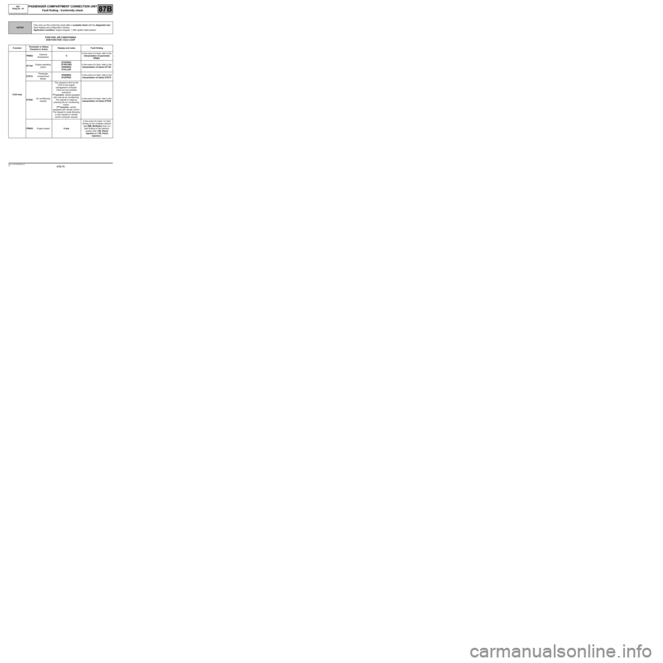
FUNCTION: AIR CONDITIONING
SUB-FUNCTION: COLD LOOP
NOTESOnly carry out this conformity check after a complete check with the diagnostic tool
(fault reading and configuration checks).
Application condition: engine stopped, + after ignition feed present.
FunctionParameter or Status
Checked or ActionDisplay and notes Fault finding
Cold loopPR002:External
temperature˚CIn the event of a fault, refer to the
interpretation of parameter
PR002.
ET142:Engine operating
phaseSTOPPED
STARTING
RUNNING
STALLEDIn the event of a fault, refer to the
interpretation of status ET142.
ET015:Passenger
compartment
blowerRUNNING
STOPPEDIn the event of a fault, refer to the
interpretation of status ET015.
ET030:Air conditioning
requestThis request is sent by the
UCH to the engine
management computer.
There are two possible
scenarios:
1
st scenario: vehicle equipped
with manual air conditioning.
The request is made by
pressing the air conditioning
button.
2
nd scenario: vehicle
equipped with climate control.
The request is made following
a user request or climate
control computer request.In the event of a fault, refer to the
interpretation of status ET030.
PR025:Engine speed0 rpmIn the event of a fault, run fault
finding on the multiplex network
(see 88B, Multiplex) then run
fault finding on the injection
system (see 13B, Diesel
injection or 17B, Petrol
injection).
Page 88 of 179
87B-88
MR-413-X44-87B000$576.mif
V5
PASSENGER COMPARTMENT CONNECTION UNIT
Fault finding - Interpretation of statuses
UCH
Vdiag No.: 44
87B
ET015
CONTINUED
Check the insulation, continuity and the absence of interference resistance on the following connections:
Manual air conditioning between the air conditioning control panel (component code 319) and the blower unit:
Connection code 38AH between components 319 and 164.
Connection code 38AJ between components 319 and 164.
Connection code 38AK between components 319 and 164.
Connection code 38AL between components 319 and 164.
Connection code 38DA between components 164 and 1156.
Connection code 38DB between components 164 and 1156.
Connection code SP3 between components 164 and 1016.
Between the air conditioning control panel (component code 319) and the UCH: Climate control:
Connection code 38LQ between components 319 and 645.
Connection code 15M between components 319 and 645.
Connection code 15A between components 319 and 645.
Connection code 38LQ between components 319 and 645.
Connection code 38ES between components 319 and 645.
Connection code SP2 between component 319 and earth.
Connection code LPD between component 319 and earth.
Connection code SP3 between components 164 and 1016.
Connection code SP3 between components 164 and 1428.
Connection code NAM between component 319 and earth.
Connection code MAN between component 319 and earth.
If the connection or connections are faulty and there is a repair procedure (see Technical Note 6015A, Electrical
wiring repair, Wiring: Precautions for repair), repair the wiring, otherwise replace it.
If the fault is still present, contact Techline.
AFTER REPAIRRepeat the conformity check from the start.
Carry out fault finding on the system.
Page 92 of 179
87B-92
MR-413-X44-87B000$576.mif
V5
PASSENGER COMPARTMENT CONNECTION UNIT
Fault finding - Interpretation of statuses
UCH
Vdiag No.: 44
87B
ET028
CONTINUED
Check the insulation, continuity and absence of interference resistance of the following connections:
●Connection code 15A between components 319 and 645.
●Connection code 15M between components 319 and 645.
●Connection codes LPD and SP2 between components 319 and 1016.
If the connection or connections are faulty and there is a repair procedure (see Technical Note 6015A, Electrical
wiring repair, Wiring: Precautions for repair), repair the wiring, otherwise replace it.
If the fault is still present, replace the rear screen de-icing button (component code 319) (see MR 411
mechanical systems 61A heating control panel or 62B Climate control panel).
If the fault is still present, contact the Techline.
AFTER REPAIRRepeat the conformity check from the start.
Carry out fault finding on the system.
Page 93 of 179
87B-93
MR-413-X44-87B000$576.mif
V5
PASSENGER COMPARTMENT CONNECTION UNIT
Fault finding - Interpretation of statuses
UCH
Vdiag No.: 44
87B
ET029
AIR CONDITIONING BUTTON
NOTESNo faults should be present or stored.
Apply this status for vehicles with manual climate control or heating.
SPECIFICATIONSPRESSED
RELEASED
Check the configuration of the heating and air conditioning type of the vehicle:
–Check that LC013 "Air conditioning type" is "Heating" or "Manual" or "Automatic" according to the
equipment level. Otherwise carry out CF019 Air conditioning type.
Check the operation of the air conditioning button indicator light AC015 “Air conditioning button indicator
light”.
Check that fuses F29 (15A) and F42 (10 A) are sound and correctly fitted in the passenger compartment fuse and
relay box (component code 1016).
Replace the fuse(s) if necessary.
Check the air conditioning control panel black 9-track connector, (component code 319) (bent, oxidised or
broken tabs).
Check that the earth on connection NAM of the manual air conditioning control panel black 9-track connector is
in perfect condition.
Check for + 12 V accessories feed on connections LPD and SP2 of the manual air conditioning control panel
black 9-track connector.
Check the PE2 40-track connector of the UCH, component code 645 (tabs bent, oxidised, broken).
If the connector is faulty and there is a repair method (see Technical Note 6015A, Repairing electrical wiring,
Wiring: Precautions for repair), repair the wiring, otherwise replace the wiring.
AFTER REPAIRRepeat the conformity check from the start.
Carry out fault finding on the system.
UCH_V44_ET029