torque RENAULT TWINGO 2009 2.G Engine And Peripherals Workshop Manual
[x] Cancel search | Manufacturer: RENAULT, Model Year: 2009, Model line: TWINGO, Model: RENAULT TWINGO 2009 2.GPages: 652
Page 431 of 652
14A-13
ANTIPOLLUTION
Exhaust gas cooler: Removal - Refitting
K9K
14A
II - REFITTING OPERATION FOR PART
CONCERNED
aOn the workbench, refit the following to the intercoo-
ler:
-a new mounting seal on the gearbox side,
-the mounting on the gearbox side,
-the mounting bolts (gearbox side) onto the inter-
cooler without tightening them,
-a new exhaust gas recirculation rigid pipe,
-the bolts of the exhaust gas recirculation rigid pipe
bracket on the cooler without tightening them.
aFit the exhaust gas recirculation assembly onto the
cylinder head.
aAdjust the mounting (gearbox side) and the exhaust
gas recirculation rigid pipe until they are flat against
the cylinder head.
aFit the exhaust gas recirculation unit assembly bolts,
without tightening them.
aTighten the bolts of the mounting (gearbox side) and
of the exhaust gas recirculation rigid pipe on the ex-
haust gas cooler to secure them on the exhaust gas
cooler.
aRemove the exhaust gas recirculation assembly.
aOn the workbench, torque tighten:
-the mounting bolts (gearbox side) on the cooler
(12 N.m),
-the bolts of the exhaust gas recirculation rigid
pipe on the exhaust gas cooler (12 N.m),
-the bolts of the exhaust gas recirculation rigid
pipe bracket (25 N.m).aOn the workbench, refit the following to the intercoo-
ler:
-a new mounting seal on the gearbox side,
-the mounting on the gearbox side,
-the mounting bolts (gearbox side) onto the inter-
cooler without tightening them,
-a new mounting seal on the timing end,
-the mounting on the timing end,
-the mounting bolts (timing end) onto the intercooler
without tightening them.
aFit the exhaust gas recirculation assembly onto the
cylinder head.
aAdjust the two mountings until they are flat against
the cylinder head.
aFit the exhaust gas recirculation unit assembly bolts,
without tightening them.
aTighten the bolts of the two mountings on the ex-
haust gas cooler to immobilise them on the exhaust
gas cooler.
aRemove the exhaust gas recirculation assembly.
aOn the workbench, torque tighten the mounting
bolts on the cooler (12 N.m).
III - FINAL OPERATION
aRefit the exhaust gas recirculation assembly (see
14A, Antipollution, Exhaust gas recirculation as-
sembly: Removal - Refitting, page 14A-15) . K9K, and 718
Note:
The cooler must absolutely be able to move in
relation to the mounting (gearbox side) and to the
exhaust gas recirculation rigid pipe so that it can
be properly adjusted afterwards on the cylinder
head.
K9K, and 740
Note:
The cooler must absolutely be able to move in
relation to its tw o mountings so that it can be
properly adjusted afterwards on the cylinder
head.
Page 432 of 652
14A-14
ANTIPOLLUTION
Exhaust gas cooler: Removal - Refitting
K9K
14A
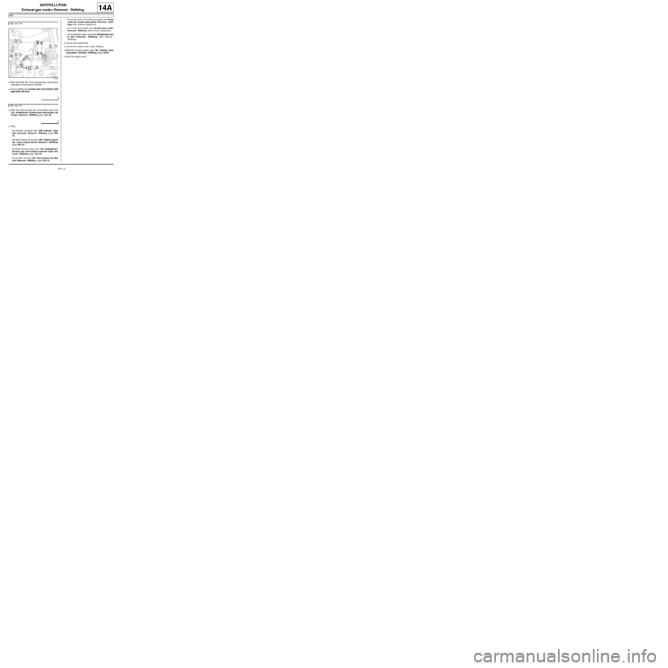
aRefit the bolts (4) of the exhaust gas recirculation
rigid pipe on the exhaust manifold.
aTorque tighten the exhaust gas recirculation rigid
pipe bolts (36 N.m).
aRefit the rigid exhaust gas recirculation pipe (see
14A, Antipollution, Exhaust gas recirculation rig-
id pipe: Removal - Refitting, page 14A-19) .
aRefit:
-the catalytic converter (see 19B, Exhaust, Cata-
lytic converter: Removal - Refitting, page 19B-
12) ,
-the lower engine tie-bar (see 19D, Engine mount-
ing, Lower engine tie-bar: Removal - Refitting,
page 19D-18) ,
-the EGR solenoid valve (see 14A, Antipollution,
Exhaust gas recirculation solenoid valve: Re-
moval - Refitting, page 14A-10) ,
-the air filter unit (see 12A, Fuel mixture, Air filter
unit: Removal - Refitting, page 12A-13) ,-the scoop under the scuttle panel grille (see Scoop
under the scuttle panel grille: Removal - Refit-
ting) (56A, Exterior equipment),
-the scuttle panel grille (see Scuttle panel grille:
Removal - Refitting) (56A, Exterior equipment),
-the windscreen wiper arms (see Windscreen wip-
er arm: Removal - Refitting) (85A, Wiping -
Washing),
aTop up the coolant level.
aConnect the battery (see ) (80A, Battery).
aBleed the cooling system (see 19A, Cooling, Cool-
ing system: Draining - Refilling, page 19A-9) .
aRefit the engine cover. K9K, and 718
141224
K9K, and 740
Page 433 of 652
14A-15
ANTIPOLLUTION
Exhaust gas recirculation assembly: Removal - Refitting
K9K
14A
REMOVAL
I - REMOVAL PREPARATION OPERATION
aPosition the vehicle on a two-post lift (see Vehicle:
Towing and lifting) (02A, Lifting equipment).
aDisconnect the battery (see ) (80A, Battery).
aRemove:
-the engine cover,
-the windscreen wiper arms (see Windscreen wip-
er arm: Removal - Refitting) (85A, Wiping -
Washing)
-the scuttle panel grille (see Scuttle panel grille:
Removal - Refitting) (56A, Exterior equipment),
-the scoop under the scuttle panel grille (see Scoop
under the scuttle panel grille: Removal - Refit-
ting) (56A, Exterior equipment),
-the air filter unit (see 12A, Fuel mixture, Air filter
unit: Removal - Refitting, page 12A-13) ,
-the EGR solenoid valve (see 14A, Antipollution,
Exhaust gas recirculation solenoid valve: Re-
moval - Refitting, page 14A-10) ,
-the lower engine tie-bar (see 19D, Engine mount-
ing, Lower engine tie-bar: Removal - Refitting,
page 19D-18) ,
-the catalytic converter (see 19B, Exhaust, Cata-
lytic converter: Removal - Refitting, page 19B-
12) ,
-the rigid exhaust gas recirculation pipe (see 14A,
Antipollution, Exhaust gas recirculation rigid
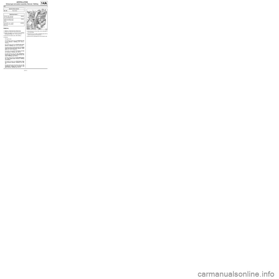
pipe: Removal - Refitting, page 14A-19) .aUndo the clip (1) of the air filter unit air outlet pipe on
the turbocharger.
aDisconnect the oil vapour rebreathing pipe (2) by
carefully separating the brackets (3) .
aRemove the air outlet pipe from the air filter box (4) . Special tooling required
Ms. 583Pipe clamps .
Tightening torquesm
exhaust gas recircula-
tion unit assembly bolts25 N.m
coolant circulation cover
bolts on the exhaust gas
cooler12 N.m
intercooler air outlet
pipe clip at the damper
valve end5.5 N.m
121633
Page 435 of 652
14A-17
ANTIPOLLUTION
Exhaust gas recirculation assembly: Removal - Refitting
K9K
14A
II - OPERATION FOR REMOVAL OF PART
CONCERNED
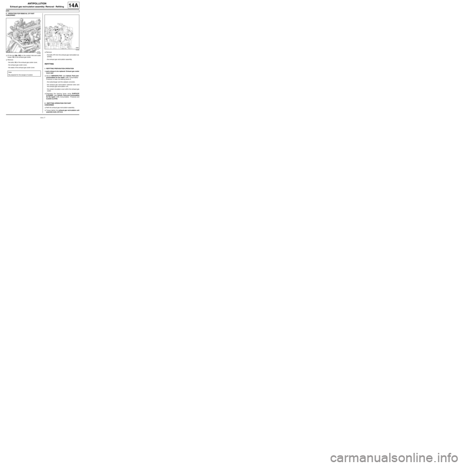
aFit the tool (Ms. 583) on the coolant inlet and outlet
hoses (15) of the exhaust gas cooler.
aRemove:
-the bolts (16) of the exhaust gas cooler cover,
-the exhaust gas cooler cover,
-the seals of the exhaust gas cooler cover.aRemove:
-the bolts (17) from the exhaust gas recirculation as-
sembly,
-the exhaust gas recirculation assembly.
REFITTING
I - REFITTING PREPARATION OPERATION
aparts always to be replaced: Exhaust gas cooler
cover seal.
aUse an ABRASIVE PAD (see Vehicle: Parts and
consumables for the repair) (04B, Consumables -
Products) to clean the bearing faces of:
-the turbocharger and the catalytic converter,
-the exhaust gas recirculation solenoid valve and
the exhaust gas recirculation unit,
-the coolant circulation cover within the exhaust gas
cooler.
aDegrease the bearing faces using SURFACE
CLEANER (see Vehicle: Parts and consumables
for the repair) (04B, Consumables - Products) and
CLEAN CLOTHS.
II - REFITTING OPERATION FOR PART
CONCERNED
aRefit the exhaust gas recirculation assembly.
aTorque tighten the exhaust gas recirculation unit
assembly bolts (25 N.m).
121639
Note:
Be prepared for the escape of coolant.
135460
Page 436 of 652
14A-18
ANTIPOLLUTION
Exhaust gas recirculation assembly: Removal - Refitting
K9K
14A
aRefit:
-new seals on the coolant circulation cover,
-the coolant circulation cover on the exhaust gas
cooler.
aTorque tighten the coolant circulation cover bolts
on the exhaust gas cooler (12 N.m).
aRemove the tool (Ms. 583) from the coolant inlet and
outlet hoses of the exhaust gas cooler.
III - FINAL OPERATION
aFit the intercooler air outlet pipe at the damper valve
end.
aConnect the intercooler air outlet pipe on the side of
the damper valve.
aTorque tighten the intercooler air outlet pipe clip
at the damper valve end (5.5 N.m).
aRefit the intercooler air outlet pipe nut on the lifting
eye.
aConnect the turbocharging pressure regulator vacu-
um pipe.
aClip:
-the turbocharging pressure regulator vacuum pipe,
-the vacuum pipe from the brake servo.
aConnect the brake servo vacuum pipe.
aFit the intercooler air inlet pipe at the turbocharger
end.
aRefit the intercooler air inlet pipe nut at the turbo-
charger end on the lifting eye.
aConnect the intercooler air inlet pipe at the turbo-
charger end.
aClip on the intercooler air inlet pipe clip at the turbo-
charger end.
aRefit the air outlet pipe onto the air filter unit.
aTighten the air filter unit air outlet pipe clip on the tur-
bocharger.
aConnect the oil vapour rebreathing pipe.
aRefit:
-the exhaust gas recirculation rigid pipe (see 14A,
Antipollution, Exhaust gas recirculation rigid
pipe: Removal - Refitting, page 14A-19) ,-the catalytic converter (see 19B, Exhaust, Cata-
lytic converter: Removal - Refitting, page 19B-
12) ,
-the lower engine tie-bar (see 19D, Engine mount-
ing, Lower engine tie-bar: Removal - Refitting,
page 19D-18) ,
-the EGR solenoid valve (see 14A, Antipollution,
Exhaust gas recirculation solenoid valve: Re-
moval - Refitting, page 14A-10) ,
-the air filter unit (see 12A, Fuel mixture, Air filter
unit: Removal - Refitting, page 12A-13) ,
-the scoop under the scuttle panel grille (see Scoop
under the scuttle panel grille: Removal - Refit-
ting) (56A, Exterior equipment).
-the scuttle panel grille (see Scuttle panel grille:
Removal - Refitting) (56A, Exterior equipment),
-the windscreen wiper arms (see Windscreen wip-
er arm: Removal - Refitting) (85A, Wiping -
Washing),
aConnect the battery (see ) (80A, Battery).
aFill and bleed the cooling system (see 19A, Cool-
ing, Cooling system: Draining - Refilling, page
19A-9) .
aRefit the engine cover. K9K, and 718
Page 437 of 652
14A-19
ANTIPOLLUTION
Exhaust gas recirculation rigid pipe: Removal - Refitting
K9K
14A
REMOVAL
I - REMOVAL PREPARATION OPERATION
aPosition the vehicle on a two-post lift (see Vehicle:
Towing and lifting) (02A, Lifting equipment).
aDisconnect the battery (see ) (80A, Battery).
aRemove:
-the engine cover,
-the windscreen wiper arms (see Windscreen wip-
er arm: Removal - Refitting) (85A, Wiping -
Washing),
-the scuttle panel grille (see Scuttle panel grille:
Removal - Refitting) (56A, Exterior equipment),
-the scoop under the scuttle panel grille (see Scoop
under the scuttle panel grille: Removal - Refit-
ting) (56A, Exterior equipment),
-the air filter unit (see 12A, Fuel mixture, Air filter
unit: Removal - Refitting, page 12A-13) ,
-the lower engine tie-bar (see 19D, Engine mount-
ing, Lower engine tie-bar: Removal - Refitting,
page 19D-18) ,
-the catalytic converter (see 19B, Exhaust, Cata-
lytic converter: Removal - Refitting, page 19B-
12) .II - OPERATION FOR REMOVAL OF PART
CONCERNED
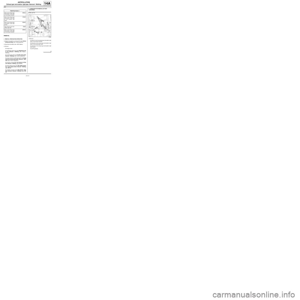
aRemove:
-the bolts (1) from the exhaust gas recirculation rigid
pipe on the exhaust manifold,
-the bolts (2) of the exhaust gas recirculation rigid
pipe on the exhaust gas cooler,
-the bolts (3) of the exhaust gas recirculation rigid
pipe bracket,
-the EGR rigid pipe. Tightening torquesm
bolts of the exhaust gas
recirculation rigid pipe
on the exhaust manifold36 N.m
bolts of the exhaust gas
recirculation rigid pipe
on the exhaust gas
cooler12 N.m
bolts of the exhaust gas
recirculation rigid pipe
bracket25 N.m
rigid exhaust gas recir-
culation pipe clip5 N.m
bolts of the exhaust gas
recirculation rigid pipe
on the exhaust manifold36 N.m
K9K, and 718
141224
Page 438 of 652
14A-20
ANTIPOLLUTION
Exhaust gas recirculation rigid pipe: Removal - Refitting
K9K
14A
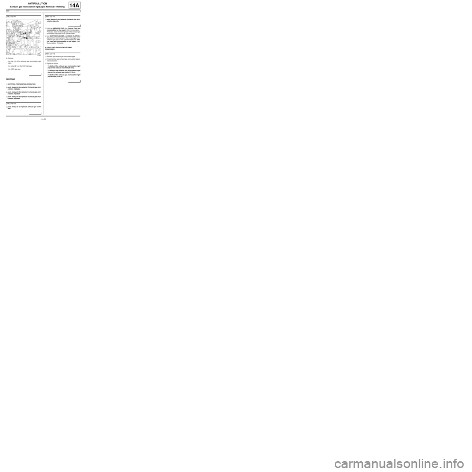
aRemove:
-the clip (4) of the exhaust gas recirculation rigid
pipe,
-the bolts (5) from the EGR rigid pipe,
-the EGR rigid pipe.
REFITTING
I - REFITTING PREPARATION OPERATION
aparts always to be replaced: Exhaust gas recir-
culation rigid pipe
aparts always to be replaced: exhaust gas recir-
culation pipe bolt
aparts always to be replaced: Exhaust gas recir-
culation pipe seal
aparts always to be replaced: exhaust gas cooler
sealaparts always to be replaced: Exhaust gas recir-
culation pipe clip
aUsing an ABRASIVE PAD (see Vehicle: Parts and
consumables for the repair) (04B, Consumables -
Products), clean the bearing face of the exhaust gas
recirculation rigid pipe on the cylinder head.
aUse SURFACE CLEANER and CLEAN CLOTHS to
degrease the bearing face of the exhaust gas recir-
culation rigid pipe on the cylinder head (see Vehi-
cle: Parts and consumables for the repair) (04B,
Consumables - Products).
II - REFITTING OPERATION FOR PART
CONCERNED
aRefit the rigid exhaust gas recirculation pipe.
aCheck that the rigid exhaust gas recirculation pipe is
not constrained.
aTighten to torque:
-the bolts of the exhaust gas recirculation rigid
pipe on the exhaust manifold (36 N.m),
-the bolts of the exhaust gas recirculation rigid
pipe on the exhaust gas cooler (12 N.m),
-the bolts of the exhaust gas recirculation rigid
pipe bracket (25 N.m). K9K, and 740
114531
K9K, and 718
K9K, and 740
K9K, and 718
Page 439 of 652
14A-21
ANTIPOLLUTION
Exhaust gas recirculation rigid pipe: Removal - Refitting
K9K
14A
aRefit the exhaust gas recirculation rigid pipe with a
new clip.
aFit the rigid exhaust gas recirculation pipe bolts,
without tightening them.
aAdjust the rigid exhaust gas recirculation pipe in re-
lation to the exhaust gas recirculation assembly.
aTorque tighten the rigid exhaust gas recirculation
pipe clip (5 N.m).
aCheck that the rigid exhaust gas recirculation pipe is
not constrained.
aTorque tighten the bolts of the exhaust gas recir-
culation rigid pipe on the exhaust manifold (36
N.m).
III - FINAL OPERATION
aRefit:
-the catalytic converter (see 19B, Exhaust, Cata-
lytic converter: Removal - Refitting, page 19B-
12) ,
-the lower engine tie-bar (see 19D, Engine mount-
ing, Lower engine tie-bar: Removal - Refitting,
page 19D-18) ,
-the air filter unit (see 12A, Fuel mixture, Air filter
unit: Removal - Refitting, page 12A-13) ,
-the scoop under the scuttle panel grille (see Scoop
under the scuttle panel grille: Removal - Refit-
ting) (56A, Exterior equipment),
-the scuttle panel grille (see Scuttle panel grille:
Removal - Refitting) (56A, Exterior equipment),
-the windscreen wiper arms (see Windscreen wip-
er arm: Removal - Refitting) (85A, Wiping -
Washing),
-the engine cover.
aConnect the battery (see ) (80A, Battery). K9K, and 740
Page 440 of 652
16A-1
STARTING - CHARGING
Alternator: Removal - Refitting
D4F or D7F, and STANDARD HEATING
16A
REMOVAL
I - REMOVAL PREPARATION OPERATION
aDisconnect the battery (see ) (MR 411, 80A, Bat-
tery).
aRemove:
-the front right-hand wheel (see Wheel: Removal -
Refitting) (MR 411, 35A, Wheels and tyres),
-the front right-hand wheel arch liner (see Front
wheel arch liner: Removal - Refitting) (MR 412,
55A, Exterior protection).
aUndo the lower bolt on the sub-frame tie-rod.
aRemove the upper bolt from the sub-frame tie-rod.
aRemove the sub-frame tie-rod.
aRemove the accessories belt (see 11A, Top and
front of engine, Accessories belt: Removal - Re-
fitting, page 11A-3) . Tightening torquesm
alter nator bolts25 Nm
sub-frame tie-rod lower
bolt62 Nm
sub-frame tie-rod upper
bolt21 Nm
Page 442 of 652
16A-3
STARTING - CHARGING
Alternator: Removal - Refitting
D4F or D7F, and STANDARD HEATING
16A
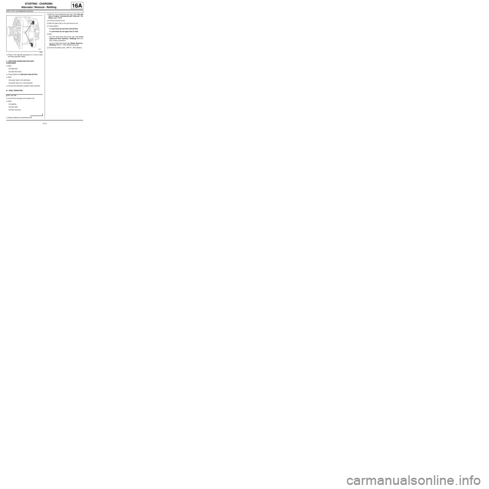
aPress in the rings (6) using pliers or a vice to make
the fitting operation easier.
II - REFITTING OPERATION FOR PART
CONCERNED
aRefit:
-the alternator,
-the alternator bolts.
aTorque tighten the alternator bolts (25 Nm).
aRefit:
-the power lead on the alternator,
-the power lead nut on the alternator.
aConnect the alternator excitation lead connector.
III - FINAL OPERATION
aConnect the fuel pipe to the injector rail.
aRefit:
-the dipstick,
-the filler neck,
-the filler neck bolt.
aAlways replace the accessories belt.aRefit the new accessories belt (see 11A, Top and
front of engine, Accessories belt: Removal - Re-
fitting, page 11A-3) .
aFit the sub-frame tie-rod.
aRefit the upper bolt on the sub-frame tie-rod.
aTorque tighten:
-the sub-frame tie-rod lower bolt (62 Nm),
-the sub-frame tie-rod upper bolt (21 Nm).
aRefit:
-the front right-hand wheel arch liner (see Front
wheel arch liner: Removal - Refitting) (MR 412,
55A, Exterior protection),
-the front right-hand wheel (see Wheel: Removal -
Refitting) (MR 411, 35A, Wheels and tyres).
aConnect the battery (see ) (MR 411, 80A, Battery).
18987
D4F, and 780