alternator belt RENAULT TWINGO 2009 2.G Engine And Peripherals User Guide
[x] Cancel search | Manufacturer: RENAULT, Model Year: 2009, Model line: TWINGO, Model: RENAULT TWINGO 2009 2.GPages: 652
Page 127 of 652
11A-10
TOP AND FRONT OF ENGINE
Accessories belt: Removal - Refitting
K9K, and STANDARD HEATING
11A
PARTS AND CONSUMABLES FOR THE
REPAIR WORK
aParts always to be replaced:
-accessories belt,
-accessories belt tensioning roller,
-accessories belt tensioning roller bolt
-the air conditioning compressor substitute pulley,
-axle sub-frame bolts.
REMOVAL
I - REMOVAL PREPARATION OPERATION
aPosition the vehicle on a two-post lift (see Vehicle:
Towing and lifting) (MR 411, 02A, Lifting equip-
ment).
aDisconnect the battery (see ) (MR 411, 80A, Bat-
tery).
aRemove:
-the front right-hand wheel (see Wheel: Removal -
Refitting) (MR 411, 35A, Wheels and tyres),
-the front right-hand wheel arch liner (see Front
wheel arch liner: Removal - Refitting) (MR 412,
55A, Exterior protection),
-the front bumper (see Front bumper: Removal -
Refitting) (MR 412, 55A, Exterior protection),
-the left-hand and right-hand headlights (see Halo-
gen headlight: Removal - Refitting) (MR 411,
80B, Headlights).aRemove:
-the air filter inlet air pipe bolt from the front upper
cross member,
-the expansion bottle bolt from the front upper cross
member,
-the cooling radiator retaining bracket bolt from the
front upper cross member.
aUnclip and then remove from the front upper cross
member:
-the air filter inlet air pipe,
-the expansion bottle.
aRemove the bonnet catch bolts.
aRemove the « cable - bonnet catch » assembly.
aRemove the front upper cross member (see Front
upper cross member: Removal - Refitting) (MR
412, 42A, Upper front structure).
II - OPERATION FOR REMOVAL OF PART
CONCERNED
1 - Removing the accessories belt
aRelax the accessories belt using a 16 mm spanner.
aRemove the accessories belt from the air condition-
ing compressor substitute pulley.
aRemove the accessories belt, passing it over its slot
between the RH side member and the crankshaft
accessories and alternator pulleys.
aDiscard the accessories belt
2 - Removing the tensioning roller and the air
conditioning compressor substitute pulley
a
aDisconnect the connector on the alternator.
aRemove the nut from the alternator harness.
aMove the alternator harness to one side.
aRemove the alternator upper bolt.
aLoosen the alternator lower bolt.
aRemove the alternator with its lower bolt fitted. Tightening torquesm
air conditioning com-
pressor substitute pul-
ley bolts25 Nm
tensioning roller bolt40 Nm
bolts mounting the mul-
tifunction support on the
cylinder block44 Nm
bolt mounting the multi-
function support on the
sump25 Nm
alter nator bolts25 Nm
Note:
The tensioning roller and air conditioning com-
pressor substitute pulley must be replaced every
time the accessor ies belt is replaced.
Page 128 of 652
11A-11
TOP AND FRONT OF ENGINE
Accessories belt: Removal - Refitting
K9K, and STANDARD HEATING
11A
aRemove:
-the multifunction support bolts from the cylinder
block,
-the multifunction support bolt from the sump,
-the equipped multifunction support.
aPlace the multifunction support in a vice.
aRemove:
-the tensioning roller bolt,
-the tensioning roller,
-the air conditioning compressor substitute pulley
bolts,
-the air conditioning compressor substitute pulley.
REFITTING
I - REFITTING OPERATION FOR PART
CONCERNED
1 - Refit the tensioning roller
aPlace the multifunction support in a vice.
aRefit:
-the new air conditioning compressor substitute pul-
ley.
-the air conditioning compressor substitute pulley
bolts,
-the new tensioning roller,
-the tensioning roller bolt,
aTorque tighten:
-the air conditioning compressor substitute pul-
ley bolts (25 Nm),
-the tensioning roller bolt (40 Nm),
aRefit:
-the equipped multifunction support,
-the multifunction support bolt onto the sump,
-the multifunction support bolts onto the cylinder
block.aTighten to torque and in order:
-the bolts mounting the multifunction support
on the cylinder block (44 Nm),
-the bolt mounting the multifunction support on
the sump (25 Nm).
aRefit:
-the alternator with its lower bolt fitted,
-the alternator upper bolt.
aTorque tighten the alternator bolts (25 Nm).
aPosition the alternator wiring harness.
aRefit the nut to the alternator wiring harness.
aAttach the connector to the alternator.
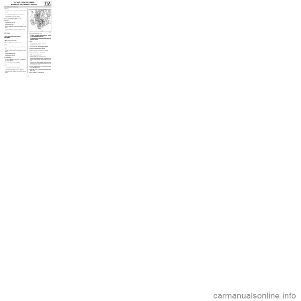
2 - Refit the accessories belt
aPartially refit the new accessories belt:
-positioning it between the air conditioning com-
pressor substitute pulley and the multifunction sup-
port,
-passing it over its slot between the RH side mem-
ber and the crankshaft accessories, tensioning roll-
er and alternator pulleys.
aTurn the accessories belt auto tensioner clockwise
using a 16 mm spanner
aFit the belt on the air conditioning compressor sub-
stitute pulley.
aGently release the tensioning roller.
120315
Page 129 of 652
11A-12
TOP AND FRONT OF ENGINE
Accessories belt: Removal - Refitting
K9K, and STANDARD HEATING
11A
aCheck that the accessories belt is correctly mounted
on the crankshaft accessories, air conditioning com-
pressor and alternator pulleys.
aTurn the engine two revolutions.
aCheck that the accessories belt is correctly fitted on
the crankshaft accessories, air conditioning com-
pressor substitute, alternator and tensioning roller
pulleys.
II - FINAL OPERATION.
aRefit the front upper cross member (see Front up-
per cross member: Removal - Refitting) (MR 412,
42A, Upper front structure).
aFit the « cable - bonnet catch » assembly.
aRefit the bonnet catch nuts.
aClip the following onto the front upper cross mem-
ber:
-the air filter inlet air pipe,
-the expansion bottle.
aRefit:
-the air filter inlet air pipe bolt onto the front upper
cross member,
-the expansion bottle bolt onto the front upper cross
member,
-the cooling radiator retaining bracket bolt onto the
front upper cross member.
-the left-hand and right-hand headlights (see Halo-
gen headlight: Removal - Refitting) (MR 411,
80B, Headlights).
-the front bumper (see Front bumper: Removal -
Refitting) (MR 412, 55A, Exterior protection),
-the front right-hand wheel arch liner (see Front
wheel arch liner: Removal - Refitting) (MR 412,
55A, Exterior protection),
-the front right-hand wheel (see Wheel: Removal -
Refitting) (MR 411, 35A, Wheels and tyres),
aConnect the battery (see ) (MR 411, 80A, Battery).
aAdjust the headlights (see Halogen headlight: Ad-
justment) (MR 411, 80B, Headlights).
Page 132 of 652
11A-15
TOP AND FRONT OF ENGINE
Accessories belt: Removal - Refitting
D4F, and 780 or 782, and STANDARD HEATING
11A
aTension the accessories belt by turning the tension-
ing roller anti-clockwise with a 20 mm open-jawed
spanner.
aAdjust the accessories belt tension using the (Mot.
1715) or (Mot. 1505) (see ) (Technical Note 3786A,
10A, Engine and peripherals).
aWithout locking, tighten the bolt (5) on the tensioning
roller with a 16 mm open-jawed spanner, while
keeping the tensioning roller tension at the adjust-
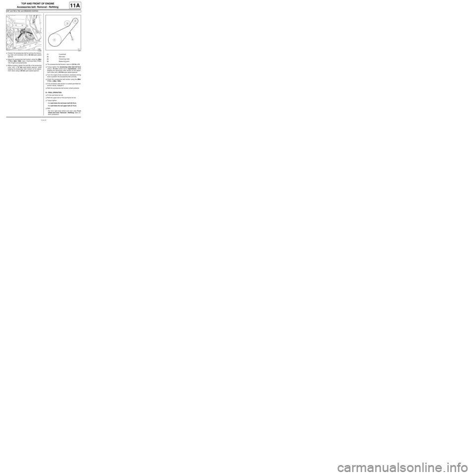
ment value using a 20 mm open-jawed spanner.aThe accessories belt tension value is 210 Hz ±± ± ±
10.
aTorque tighten the tensioning roller bolt (44 N.m)
using a 16 mm socket and a repositioner, while
keeping the tensioning roller tension at the adjust-
ment value with a 20 mm open-jawed spanner.
aTurn the engine three revolutions clockwise (timing
end) to position the accessories belt correctly.
aCheck the accessories belt tension using the (Mot.
1715) or (Mot. 1505).
aIf the accessory belt tension is outside permitted tol-
erance values, readjust it.
aRefit the accessories belt tension wheel protector.
III - FINAL OPERATION
aFit the sub-frame tie-rod.
aRefit the upper bolt on the sub-frame tie-rod.
aTorque tighten:
-the sub-frame tie-rod lower bolt (62 N.m),
-the sub-frame tie-rod upper bolt (21 N.m).
aRefit:
-the front right-hand wheel arch liner (see Front
wheel arch liner: Removal - Refitting) (55A, Ex-
terior protection),
11038213511
(1) Crankshaft
(2) Alternator
(3) Tensioning roller
(4) Measur ing point
Page 295 of 652
12A-30
FUEL MIXTURE
Inlet distributor: Removal - Refitting
D7F
12A
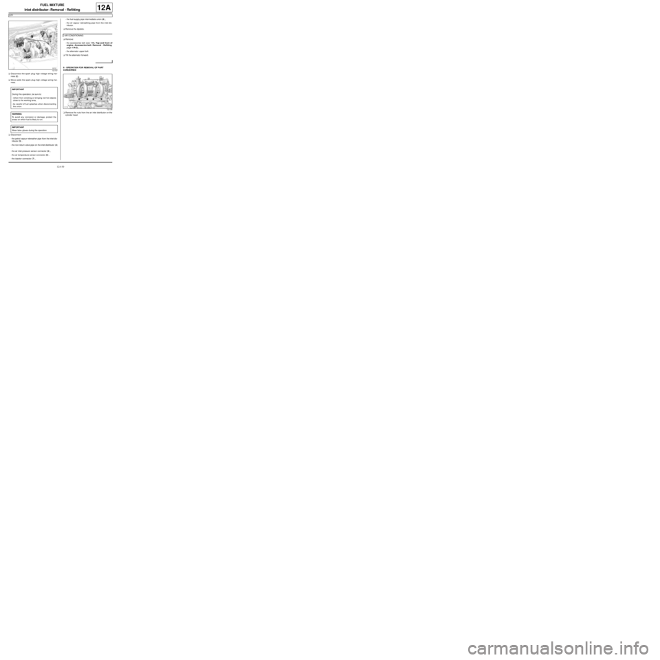
aDisconnect the spark plug high voltage wiring har-
ness (2) .
aMove aside the spark plug high voltage wiring har-
ness.
aDisconnect:
-the petrol vapour rebreather pipe from the inlet dis-
tributor (3) ,
-the non-return valve pipe on the inlet distributor (4)
,
-the air inlet pressure sensor connector (5) ,
-the air temperature sensor connector (6) ,
-the injector connector (7) ,-the fuel supply pipe intermediate union (8) ,
-the oil vapour rebreathing pipe from the inlet dis-
tributor.
aRemove the dipstick.
aRemove:
-the accessories belt (see 11A, Top and front of
engine, Accessories belt: Removal - Refitting,
page 11A-3) ,
-the alternator upper bolt.
aTilt the alternator forward.
II - OPERATION FOR REMOVAL OF PART
CONCERNED
aRemove the nuts from the air inlet distributor on the
cylinder head.
121737
IMPORTANT
During this operation, be sure to:
-refrain from smoking or bringing red hot objects
close to the working area,
-be careful of fuel splashes when disconnecting
the union.
WARNING
To avoid any corrosion or damage, protect the
areas on which fuel is likely to run.
IMPORTANT
Wear latex gloves during the operation.
AIR CONDITIONING
121734
Page 297 of 652
12A-32
FUEL MIXTURE
Inlet distributor: Removal - Refitting
D7F
12A
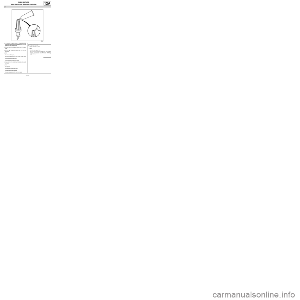
aIt is essential to apply a bead of FLUORSTAR 2L
grease with a diameter of 2 mm around the inner
edge of the high tension caps.
aConnect the high voltage wiring harness to the spark
plugs.
aClip the high voltage wiring harness onto the inlet
distributor.
aRefit:
-the intermediate plate,
-the intermediate bracket bolts on the throttle valve,
-the motorised throttle valve,
-the motorised throttle valve bolts.
aTorque tighten the motorised throttle valve bolts
(10 N.m)
aRefit:
-the dipstick,
-the air filter unit air outlet pipe.
-the air filter unit air inlet pipe,
-the air inlet scoop on the front end panel.aFit the alternator in place.
aRefit:
-the alternator upper bolt,
-the accessories belt (see 11A, Top and front of
engine, Accessories belt: Removal - Refitting,
page 11A-3) .
106640
AIR CONDITIONING
Page 363 of 652
13B-2
DIESEL INJECTION
Diesel injection: Precautions for the repair
K9K
13B
II - ADVICE TO BE FOLLOWED BEFORE ANY
OPERATION
1) Carry out the work in a clean working area and take
care to protect removed components from dust using
plastic bags which are hermetically-resealable, for ex-
ample.
2) Always order the following from the Parts Depart-
ment before carrying out work:
-a new set of blanking plugs, specific to the engine,
-enough lint-free cleaning cloths.
-one of the two cleaning products for fuel pipe
unions,
-the parts that are always to be replaced after each
removal operation, mentioned in the operational pro-
cedures specific to the vehicle (see related Workshop
Repair Manual).
3) Wear safety goggles fitted with side shields to pre-
vent the cleaning product from splashing the eyes.
4) Wear leaktight protective gloves (Nitrile type) to
avoid prolonged contact with the skin.
5) Before carrying out work on the injection system,
use plastic bags or clean rags, for example, to protect:
-the accessories and timing belts,
-the electrical accessories (starter, alternator, power-
assisted steering pump, sensors and electrical con-
nectors),
-the flywheel face.
III - INSTRUCTIONS TO BE FOLLOWED DURING
THE OPERATION
Wash your hands before and while carrying out the
work.
Replace leaktight protective gloves (Nitrile type) when
they are soiled or damaged.
All components removed from the injection system
must be stored in a hermetically sealed plastic bag
once they have been capped.
Reseal the bag hermetically, for example using adhe-
sive tape, even if the bag must be opened shortly after-
wards: ambient air can be a source of impurities.After opening the fuel circuit, the use of brushes, clean-
ing agents, air blow guns, rifle-type brushes or stan-
dard cloths is strictly prohibited: these items are likely
to allow impurities to enter the system.
When replacing a component with a new one or when
refitting it after storing it in a plastic bag, do not unpack
it until it is time to fit it on the vehicle.
IV - CLEANING
There are currently two procedures for cleaning the
fuel circuit before opening it in order to carry out work in
the workshop.
These procedures enable the fuel circuit to be cleaned
to prevent contamination from entering: they both have
the same end result and neither is preferred over the
other.
1 - Cleaning using injector cleaner
Clear the access to the unions that need opening, fol-
lowing the work procedures specific to the vehicle (see
the relevant Workshop Repair Manual).
Protect sections which are sensitive to fuel leaks.
Pour the injector cleaning agent into a container which
is free from impurities.
Dip a clean brush, which is not shedding bristles, into
the container of injector cleaning agent.
Clean the unions carefully using the brush and the in-
jector cleaning agent.
Blast the components that have been cleaned with
compressed air (tools, workbench, and also parts,
unions and around the injection system). Check that no
bristles from the brush have come away and that the
area is clean.
Wipe the sections that were cleaned with fresh clean-
ing cloths.
Open the circuit at the unions and immediately fit the
relevant blanking plugs. Note:
When using leather protective gloves, wear a pair of
leaktight protective gloves (Nitrile type) over the top.
IMPORTANT
Wear leaktight gloves (Nitrile type) for this opera-
tion.
IMPORTANT
Wear goggles with side protectors for this opera-
tion.
Page 385 of 652
13B-24
DIESEL INJECTION
High pressure pump: Removal - Refitting
K9K
13B
aRefit the lower timing cover.
aRefit the accessories belt (see 11A, Top and front
of engine, Accessories belt: Removal - Refitting,
page 11A-3)
aRefit:
-the upper timing cover,
-the camshaft position sensor (see 13B, Diesel in-
jection, Camshaft position sensor: Removal -
Refitting, page 13B-14) ,
-the right-hand suspended engine mounting (see
19D, Engine mounting, Right-hand suspended
engine mounting: Removal - Refitting, page
19D-13) .
aRemove the blanking plugs.
aRefit a high pressure pipe between the pump and
the rail (see 13B, Diesel injection, High pressure
pipe between pump and rail: Removal - Refitting,
page 13B-35) .
aConnect the diesel return pipe to the venturi fitted to
the high pressure pump.aRefit:
-the fuel filter mounting,
-the fuel filter (see 13A, Fuel supply, Fuel filter:
Removal - Refitting, page 13A-4) .
aRefit:
-the engine tie-bar (see 19D, Engine mounting,
Lower engine tie-bar: Removal - Refitting, page
19D-18) ,
-the engine harness channel.
aFit the engine wiring on the engine wiring channel.
aClip on the engine wiring channel.
aConnect to the high pressure pump:
-the diesel supply pipe,
-the diesel return pipe to the diesel filter.
aClip on the high pressure pump pipes.
aRemove the protection on the alternator to prevent
fuel flowing out.
aConnect the connectors of:
-the diesel temperature sensor,
-the flow actuator,
-the injectors,
-the heater plugs.
aRemove the blanking cover which protects the oil
level dipstick guide inlet opening on the cylinder
block.
aRefit:
-the dipstick guide,
-the dipstick,
-the scoop under the scuttle panel grille (see Scoop
under the scuttle panel grille: Removal - Refit-
ting) (56A, Exterior equipment),
-the scuttle panel grille (see Scuttle panel grille:
Removal - Refitting) (56A, Exterior equipment),
-the windscreen wiper arms (see Windscreen wip-
er arm: Removal - Refitting) (85A, Wiping -
Washing).
aPrime the fuel circuit with a manual priming pump
until the disconnected pipes are filled with fuel; if
necessary, bleed the fuel filter (see 13A, Fuel sup-
ply, Fuel filter: Removal - Refitting, page 13A-4) .
aCheck that there are no fuel leaks.
aConnect the battery (see ) (80A, Battery). K9K, and 740
19659
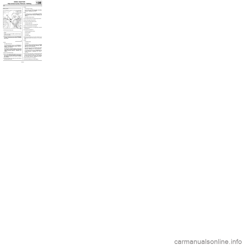
Note:
Make sure that the tab (23) is positioned oppo-
site the mark (24) .
Page 440 of 652
16A-1
STARTING - CHARGING
Alternator: Removal - Refitting
D4F or D7F, and STANDARD HEATING
16A
REMOVAL
I - REMOVAL PREPARATION OPERATION
aDisconnect the battery (see ) (MR 411, 80A, Bat-
tery).
aRemove:
-the front right-hand wheel (see Wheel: Removal -
Refitting) (MR 411, 35A, Wheels and tyres),
-the front right-hand wheel arch liner (see Front
wheel arch liner: Removal - Refitting) (MR 412,
55A, Exterior protection).
aUndo the lower bolt on the sub-frame tie-rod.
aRemove the upper bolt from the sub-frame tie-rod.
aRemove the sub-frame tie-rod.
aRemove the accessories belt (see 11A, Top and
front of engine, Accessories belt: Removal - Re-
fitting, page 11A-3) . Tightening torquesm
alter nator bolts25 Nm
sub-frame tie-rod lower
bolt62 Nm
sub-frame tie-rod upper
bolt21 Nm
Page 442 of 652
16A-3
STARTING - CHARGING
Alternator: Removal - Refitting
D4F or D7F, and STANDARD HEATING
16A
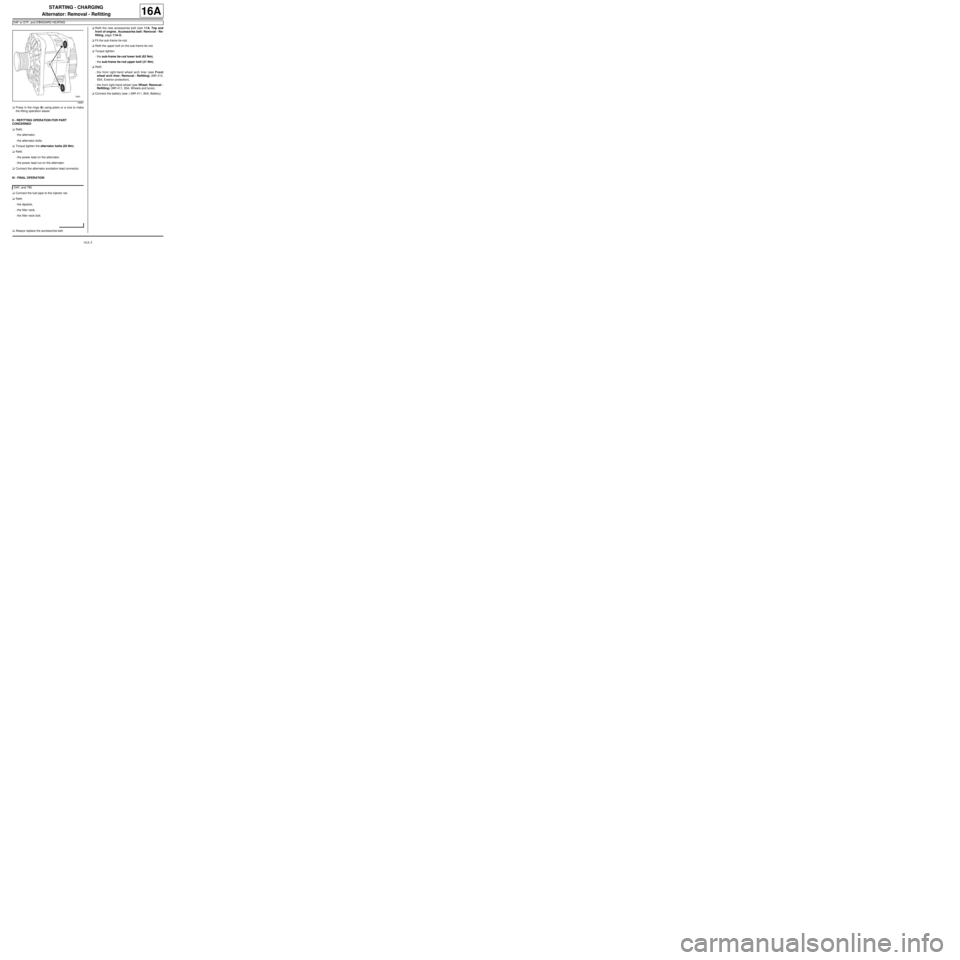
aPress in the rings (6) using pliers or a vice to make
the fitting operation easier.
II - REFITTING OPERATION FOR PART
CONCERNED
aRefit:
-the alternator,
-the alternator bolts.
aTorque tighten the alternator bolts (25 Nm).
aRefit:
-the power lead on the alternator,
-the power lead nut on the alternator.
aConnect the alternator excitation lead connector.
III - FINAL OPERATION
aConnect the fuel pipe to the injector rail.
aRefit:
-the dipstick,
-the filler neck,
-the filler neck bolt.
aAlways replace the accessories belt.aRefit the new accessories belt (see 11A, Top and
front of engine, Accessories belt: Removal - Re-
fitting, page 11A-3) .
aFit the sub-frame tie-rod.
aRefit the upper bolt on the sub-frame tie-rod.
aTorque tighten:
-the sub-frame tie-rod lower bolt (62 Nm),
-the sub-frame tie-rod upper bolt (21 Nm).
aRefit:
-the front right-hand wheel arch liner (see Front
wheel arch liner: Removal - Refitting) (MR 412,
55A, Exterior protection),
-the front right-hand wheel (see Wheel: Removal -
Refitting) (MR 411, 35A, Wheels and tyres).
aConnect the battery (see ) (MR 411, 80A, Battery).
18987
D4F, and 780