low oil pressure RENAULT TWINGO 2009 2.G Engine And Peripherals User Guide
[x] Cancel search | Manufacturer: RENAULT, Model Year: 2009, Model line: TWINGO, Model: RENAULT TWINGO 2009 2.GPages: 652
Page 117 of 652
10A-111
ENGINE AND CYLINDER BLOCK ASSEMBLY
Flywheel: Removal - Refitting
K4M
10A
-the flywheel.
REFITTING
I - REFITTING PREPARATION OPERATION
aUse SURFACE CLEANER (see Vehicle: Parts
and consumables for the repair) (04B, Consuma-
bles - Products) to clean and degrease:
-the flywheel bearing face if reusing,
-the crankshaft bearing face.
aAlways replace the flywheel bolts.
II - REFITTING OPERATION
aFit the flywheel.
aFit the new flywheel bolts without tightening them.
aPosition the (Mot. 1677).
aTighten to torque and in order the flywheel bolts
(70 N.m).
III - FINAL OPERATION
aRefit:
-the « pressure plate - disc » assembly (see Pres-
sure plate - Disc: Removal - Refitting) (20A,
Clutch),
-the manual gearbox (see Manual gearbox: Re-
moval - Refitting) (21A, Manual gearbox).-the « engine and gearbox » assembly (see 10A,
Engine and cylinder block assembly, Engine -
gearbox assembly: Removal - Refitting, page
10A-74) ,
-the differential output seals (see Differential out-
put seal: Removal - Refitting) (21A, Manual gear-
box),
-the front right-hand wheel driveshaft (see Front
right-hand driveshaft: Removal - Refitting)
(29A, Driveshafts),
-the front left-hand wheel driveshaft (see Front left-
hand driveshaft: Removal - Refitting) (29A,
Driveshafts),
-the front axle subframe (see Front axle subframe:
Removal - Refitting) (31A, Front axle compo-
nents),
-the lower engine tie-bar (see 19D, Engine mount-
ing, Lower engine tie-bar: Removal - Refitting,
page 19D-18) ,
-the front bumper (see Front bumper: Removal -
Refitting) (55A, Exterior protection),
-the front wheel arch liners (see Front wheel arch
liner: Removal - Refitting) (55A, Exterior protec-
tion),
-the front wheels (see Wheel: Removal - Refitting)
(35A, Wheels and tyres),
-the battery tray (see Battery tray: Removal - Re-
fitting) (80A, Battery),
-the petrol injection computer (see 17B, Petrol in-
jection, Petrol injection computer: Removal -
Refitting, page 17B-20) ,
-the air filter unit (see 12A, Fuel mixture, Air filter
unit: Removal - Refitting, page 12A-13) ,
-the battery (see Battery: Removal - Refitting)
(80A, Battery).
aPerform the following operations:
-fill and bleed the cooling system (see 19A, Cool-
ing, Cooling system: Draining - Refilling, page
19A-9) ,
-fill the gearbox (see Manual gearbox oils: Drain-
ing - Filling) (21A, Manual gearbox).
-fill the refrigerant circuit using a refrigerant charg-
ing station (see Refrigerant circuit: Draining -
Filling) (62A, Air conditioning).
aRefit the engine undertray.
109158
Page 149 of 652
11A-32
TOP AND FRONT OF ENGINE
Timing belt: Removal - Refitting
D4F
11A
aMove the flexible heat shield away from the oil pres-
sure sensor connector.
aDisconnect the oil pressure sensor connector (1) .
aUnclip the oil pressure sensor wiring from the upper
timing cover.
aMove the oil pressure sensor connector to one side.aRemove:
-the bolts (1) from the upper timing cover,
-the upper timing cover.
aRemove:
-the intermediate timing cover bolts (2) ,
-the timing intermediate housing,
-the lower timing cover bolt (3) ,
-the lower timing cover. D4F, and 780 or 782
122664
109740
109739
Page 154 of 652
11A-37
TOP AND FRONT OF ENGINE
Timing belt: Removal - Refitting
D4F
11A
aCheck that the tensioning roller does not come into
contact with the cylinder head.
aIf the tensioning roller is in contact with the cylinder
head:
-set the engine to Top Dead Centre,
-remove the tensioning roller and the timing belt,
-insert the tensioning roller pin,
-repeat the timing belt refitting method from the be-
ginning, step by step.
III - FINAL OPERATION
aRefit:
-the lower timing cover,
-the lower timing cover bolt,
-the timing intermediate housing,
-the intermediate timing cover bolts,
-the upper timing cover,
-the upper timing cover.
aTorque tighten:
-the lower timing cover bolt (10 N.m),
-the intermediate timing cover bolts (10 N.m),
-the upper timing cover bolts (37 N.m)aFit the oil pressure sensor connector.
aClip the oil pressure sensor wiring on the upper tim-
ing cover.
aConnect the oil pressure sensor connector.
aFit the flexible heat shield on the oil pressure sensor
connector.
aClip the fuel pipe on to the upper timing cover.
aRefit:
-the right-hand suspended engine mounting (see
19D, Engine mounting, Right-hand suspended
engine mounting: Removal - Refitting, page
19D-13) ,
-the rear suspended engine mounting (see 19D,
Engine mounting, Lower engine tie-bar: Re-
moval - Refitting, page 19D-18) .
aRemove the tool (Mot. 1379).
aRefit:
-the crankshaft accessories pulley (see 11A, Top
and front of engine, Crankshaft accessories
pulley: Removal - Refitting, page 11A-20) ,
-the accessories belt (see 11A, Top and front of
engine, Accessories belt: Removal - Refitting,
page 11A-3) ,
-the front right-hand wheel arch liner (see Front
wheel arch liner: Removal - Refitting) (55A, Ex-
terior protection),
-the front right-hand wheel (see Wheel: Removal -
Refitting) (35A, Wheels and tyres).
aConnect the battery (see ) (80A, Battery).
109765
D4F, and 780 or 782
Page 326 of 652
12B-1
TURBOCHARGING
Turbocharging: Precautions for the repair
D4F or K9K
12B
I - TURBOCHARGER: GENERAL INSTRUCTIONS
For the turbocharging pressure regulator check (see
Fault finding - Tests) (Technical Note 3419A, 12B,
Turbocharging).
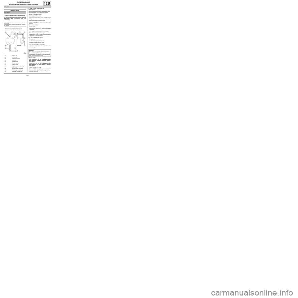
II - TURBOCHARGER CIRCUIT DIAGRAMIII - APPLICATION CONDITIONS OF
INSTRUCTIONS
The instructions below must be followed when repla-
cing a turbocharger due to mechanical damage:
-damage to the bearing system,
-broken shaft or turbine wheel,
-compressor wheel rubbing against the turbocharger
casing,
-broken or damaged compressor wheel,
-extensive clogging of the turbine wheel casing (hard
deposits).
FOR THE AIR CIRCUIT:
-Consequences:
•swarf or metal objects in the turbocharger inlet and
outlet pipes,
•oil in the air circuit (collected in the intercooler).
-Risks (after replacing the turbocharger):
•metal objects sucked in by the compressor wheel
(destruction of the turbocharger).
FOR THE LUBRICATION CIRCUIT:
-Consequences:
•swarf found in the engine oil circuit,
•circulation of swarf within the circuit.
-Risks (after replacing the turbocharger):
•premature wear on the bearing system (destruction
of turbocharger).
INSTRUCTIONS:
-Drain the engine oil (see 10A, Engine and cylinder
block assembly, Engine oil: Draining - Refilling,
page 10A-22)
-Replace the oil filter (see 10A, Engine and cylinder
block assembly, Oil filter: Removal - Refitting,
page 10A-29) .
-Replace the seals and fittings,
-Carry out the following only if the compressor wheel is
broken or rubbing against the turbocharger casing:
•Drain the intercooler, Equipment required
par ts washer
WARNING
The turbocharger pressure regulator rod must not
be adjusted.
112666
(1) Air filter unit
(2) Air flowmeter
(3) Compressor wheel
(4) Intercooler
(5) Inlet distributor
(6) Exhaust manifold
(7) Turbine wheel
(8) Bearing system (bearing +
wheel shaft)
(A) Air filter box air outlet pipe
(B) Turbocharger air outlet pipe
(C) Intercooler air outlet pipe
WARNING
Metal objects may enter the oil and air circuits as a
result of a broken turbocharger.
Failure to follow the INSTRUCTIONS listed will lead
to the turbocharger breaking again.
Page 328 of 652
12B-3
TURBOCHARGING
Turbocharging: Precautions for the repair
D4F or K9K
12B
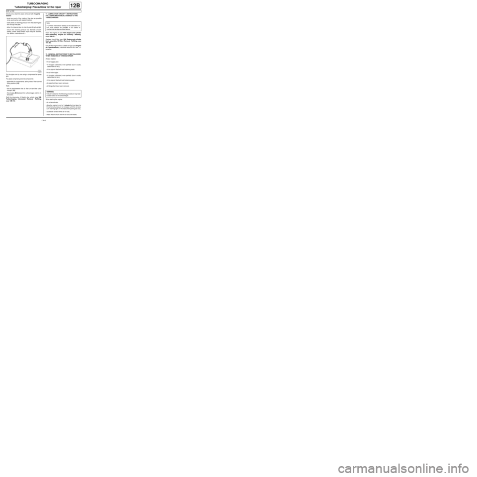
One by one, clean the pipes removed with the parts
washer :
-brush as much of the inside of the pipe as possible
(only use brushes with plastic bristles),
-wash plenty of cleaning product from the cleaning sta-
tion through the pipe,
-allow the cleaned pipe to drain by standing it upright,
-ensure the cleaning product has drained out com-
pletely (check areas where liquid may be retained,
e.g. gaiters, resonators etc.).
Dry the pipes one by one using a compressed air spray
gun.
For pipes comprising several components:
-assemble the components, taking note of their correct
fitting position (10) .
Refit:
-the air pipe(between the air filter unit and the turbo-
charger) (A) ,
-the air pipe (B) (between the turbocharger and the in-
tercooler).
Refit the intercooler, if fitted to the vehicle (see 12B,
Turbocharging, Intercooler: Removal - Refitting,
page 12B-18) .V - LUBRICATION CIRCUIT**: INSTRUCTIONS
FOLLOWING MECHANICAL DAMAGE TO THE
TURBOCHARGER
Drain the engine oil (see 10A, Engine and cylinder
block assembly, Engine oil: Draining - Refilling,
page 10A-22) .
Replace the oil filter (see 10A, Engine and cylinder
block assembly, Oil filter: Removal - Refitting, page
10A-29) .
Only fill the engine with a suitable oil type (see Engine
oil: Specifications) (Technical Note 6013A, 04A, Lu-
bricants).
VI - GENERAL INSTRUCTIONS TO BE FOLLOWED
WHEN REMOVING A TURBOCHARGER
Always replace:
-the oil supply pipe:
•if the pipe is blocked, even partially (due to scale,
carbonised oil etc.),
•if the pipe is fitted with self-retaining seals.
-the oil return pipe:
•if the pipe is blocked, even partially (due to scale,
carbonised oil etc.),
•if the pipe is fitted with self-retaining seals.
-all seals that have been removed,
-all fittings that have been removed.
When starting the engine:
-do not accelerate,
-allow the engine to run for 1 minute,the time taken for
the oil circuit pressure to increase (until the oil pres-
sure warning light on the instrument panel goes out),
-accelerate several times at no load,
-check the air circuit and the oil circuit for leaks.
112771
Note:
(**) These instructions relating to the lubrication cir-
cuit must always be followed in all cases of
mechanical damage as listed above.
WARNING
Failure to observe the following procedure may lead
to destr uction of the turbocharger.
Page 334 of 652
12B-9
TURBOCHARGING
Turbocharger: Removal - Refitting
D4F, and 780 or 782
12B
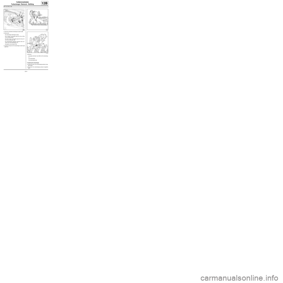
aUndo the compressor discharge air pipe clip (8) .
aDisconnect:
-the turbocharger discharge air pipe,
-the oil vapour recirculation pipe from the air filter
unit air outlet pipe (9) ,
-the petrol vapour recirculation pipe from the air fil-
ter unit air outlet pipe (10) ,
-the turbocharging regulation solenoid valve con-
nector from the turbocharger (11) ,
-the ignition coil connector (12) .
aUnclip the wiring from the turbocharger coolant rigid
pipe strut.
aRemove:
-the upper and lower nuts (13) from the turbocharg-
er,
-the turbocharger,
-the turbocharger seal.
If replacing the turbocharger
aUnclip the clips of the turbocharging pressure regu-
lation pipes.
aDisconnect the turbocharging pressure regulation
pipes.
122826121201
121202
Page 335 of 652
12B-10
TURBOCHARGING
Turbocharger: Removal - Refitting
D4F, and 780 or 782
12B
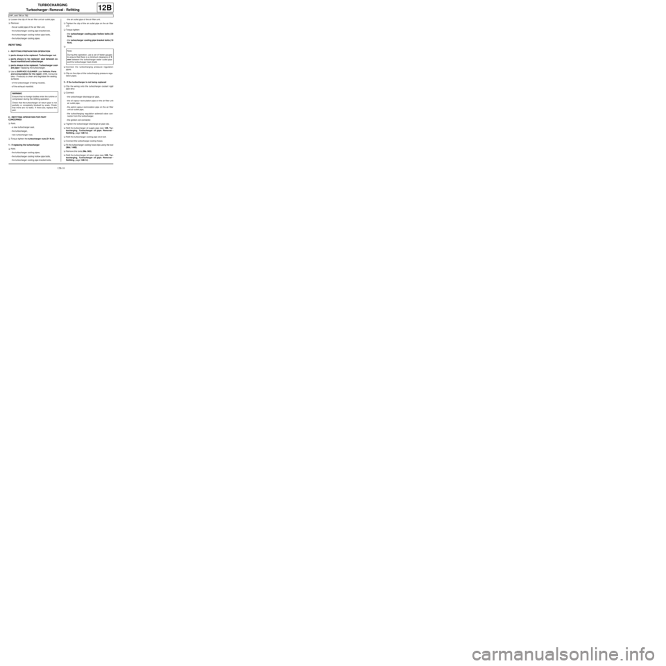
aLoosen the clip of the air filter unit air outlet pipe.
aRemove:
-the air outlet pipe of the air filter unit,
-the turbocharger cooling pipe bracket bolt,
-the turbocharger cooling hollow pipe bolts,
-the turbocharger cooling pipes.
REFITTING
I - REFITTING PREPARATION OPERATION
aparts always to be replaced: Turbocharger nut.
aparts always to be replaced: seal between ex-
haust manifold and turbocharger.
aparts always to be replaced: Turbocharger cool-
ant pipe if replacing the turbocharger.
aUse a SURFACE CLEANER (see Vehicle: Parts
and consumables for the repair) (04B, Consuma-
bles - Products) to clean and degrease the sealing
surfaces:
-of the turbocharger (if being reused),
-of the exhaust manifold.
II - REFITTING OPERATION FOR PART
CONCERNED
aRefit:
-a new turbocharger seal,
-the turbocharger,
-new turbocharger nuts.
aTorque tighten the turbocharger nuts (21 N.m).
1 - If replacing the turbocharger
aRefit:
-the turbocharger cooling pipes,
-the turbocharger cooling hollow pipe bolts,
-the turbocharger cooling pipe bracket bolts,-the air outlet pipe of the air filter unit.
aTighten the clip of the air outlet pipe on the air filter
unit.
aTorque tighten:
-the turbocharger cooling pipe hollow bolts (30
N.m),
-the turbocharger cooling pipe bracket bolts (10
N.m).
a
aConnect the turbocharging pressure regulation
pipes.
aClip on the clips of the turbocharging pressure regu-
lation pipes.
2 - If the turbocharger is not being replaced
aClip the wiring onto the turbocharger coolant rigid
pipe strut.
aConnect:
-the turbocharger discharge air pipe,
-the oil vapour recirculation pipe on the air filter unit
air outlet pipe,
-the petrol vapour recirculation pipe on the air filter
unit air outlet pipe,
-the turbocharging regulation solenoid valve con-
nector from the turbocharger,
-the ignition coil connector.
aTighten the turbocharger discharge air pipe clip.
aRefit the turbocharger oil supply pipe (see 12B, Tur-
bocharging, Turbocharger oil pipe: Removal -
Refitting, page 12B-12) .
aRefit the turbocharger cooling pipe strut bolt.
aConnect the turbocharger cooling hoses.
aFit the turbocharger cooling hose clips using the tool
(Mot. 1448).
aRemove the tools (Ms. 583).
aRefit the turbocharger oil return pipe (see 12B, Tur-
bocharging, Turbocharger oil pipe: Removal -
Refitting, page 12B-12) . WARNING
Ensure that no foreign bodies enter the turbine or
compressor during the refitting operation.
Check that the turbocharger oil return pipe is not
partially or completely blocked by scale. Check
that there are no leaks. If there are, replace the
part.Note:
Dur ing this operation, use a set of feeler gauges
to ensure that there is a minimum clearance of 3
mm between the turbocharger water outlet pipe
and the turbocharger heat shield.
Page 377 of 652
13B-16
DIESEL INJECTION
High pressure pump: Removal - Refitting
K9K
13B
REMOVAL
I - REMOVAL PREPARATION OPERATION
aPosition the vehicle on a two-post lift (see Vehicle:
Towing and lifting) (02A, Lifting equipment).
aRemove the front engine cover.
aDisconnect the battery (see ) (80A, Battery).
aRemove:
-the windscreen wiper arms (see Windscreen wip-
er arm: Removal - Refitting) (85A, Wiping -
Washing),
-the scuttle panel grille (see Scuttle panel grille:
Removal - Refitting) (56A, Exterior equipment),-the scoop under the scuttle panel grille (see Scoop
under the scuttle panel grille: Removal - Refit-
ting) (56A, Exterior equipment).
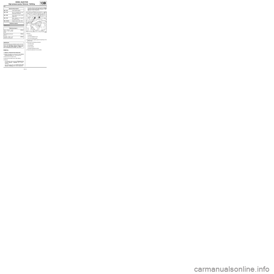
aRemove:
-the dipstick,
-the oil level dipstick nut (1) ,
-the oil level dipstick guide.
aPlug the oil level dipstick guide inlet opening on the
cylinder block.
aDisconnect the following connectors :
-the heater plugs,
-of the injectors,
-the flow actuator,
-the diesel temperature sensor.
aProtect the alternator from fuel outflow. Special tooling required
Mot. 1672Low er engine support.
Mot. 1430Set of 5 crankshaft and cam-
shaft pulley timing pins.
Mot. 1606High pressure pump pulley
support tool.
Mot. 1525Gear extractor for tapered
hub injection pump.
Mot. 1525-02Adapter claws for Mot. 1525.
Equipment required
Diagnostic tool
Tightening torquesm
high pressure pump
bolts on the cylinder
head23 N.m
high pressure pump pul-
ley nut70 N.m
cylinder head sus-
pended mounting bolts25 N.m
IMPORTANT
Consult the safety and cleanliness advice and oper-
ation recommendations before carrying out any
repair (see 13B, Diesel injection, Diesel injec-
tion: Precautions for the repair, page 13B-1) .
114527
Page 385 of 652
13B-24
DIESEL INJECTION
High pressure pump: Removal - Refitting
K9K
13B
aRefit the lower timing cover.
aRefit the accessories belt (see 11A, Top and front
of engine, Accessories belt: Removal - Refitting,
page 11A-3)
aRefit:
-the upper timing cover,
-the camshaft position sensor (see 13B, Diesel in-
jection, Camshaft position sensor: Removal -
Refitting, page 13B-14) ,
-the right-hand suspended engine mounting (see
19D, Engine mounting, Right-hand suspended
engine mounting: Removal - Refitting, page
19D-13) .
aRemove the blanking plugs.
aRefit a high pressure pipe between the pump and
the rail (see 13B, Diesel injection, High pressure
pipe between pump and rail: Removal - Refitting,
page 13B-35) .
aConnect the diesel return pipe to the venturi fitted to
the high pressure pump.aRefit:
-the fuel filter mounting,
-the fuel filter (see 13A, Fuel supply, Fuel filter:
Removal - Refitting, page 13A-4) .
aRefit:
-the engine tie-bar (see 19D, Engine mounting,
Lower engine tie-bar: Removal - Refitting, page
19D-18) ,
-the engine harness channel.
aFit the engine wiring on the engine wiring channel.
aClip on the engine wiring channel.
aConnect to the high pressure pump:
-the diesel supply pipe,
-the diesel return pipe to the diesel filter.
aClip on the high pressure pump pipes.
aRemove the protection on the alternator to prevent
fuel flowing out.
aConnect the connectors of:
-the diesel temperature sensor,
-the flow actuator,
-the injectors,
-the heater plugs.
aRemove the blanking cover which protects the oil
level dipstick guide inlet opening on the cylinder
block.
aRefit:
-the dipstick guide,
-the dipstick,
-the scoop under the scuttle panel grille (see Scoop
under the scuttle panel grille: Removal - Refit-
ting) (56A, Exterior equipment),
-the scuttle panel grille (see Scuttle panel grille:
Removal - Refitting) (56A, Exterior equipment),
-the windscreen wiper arms (see Windscreen wip-
er arm: Removal - Refitting) (85A, Wiping -
Washing).
aPrime the fuel circuit with a manual priming pump
until the disconnected pipes are filled with fuel; if
necessary, bleed the fuel filter (see 13A, Fuel sup-
ply, Fuel filter: Removal - Refitting, page 13A-4) .
aCheck that there are no fuel leaks.
aConnect the battery (see ) (80A, Battery). K9K, and 740
19659
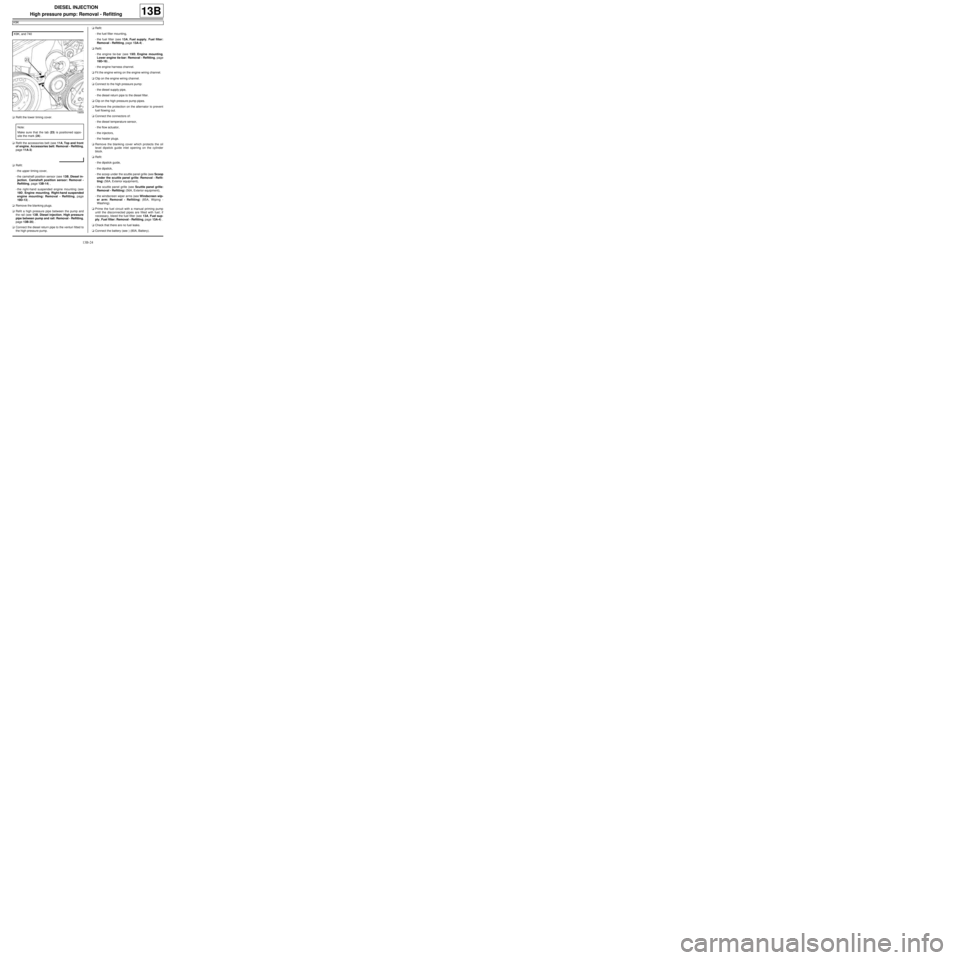
Note:
Make sure that the tab (23) is positioned oppo-
site the mark (24) .
Page 387 of 652
13B-26
DIESEL INJECTION
Flow actuator: Removal - Refitting
K9K
13B
PIECES ET INGREDIENTS POUR LA REPARATION
Pièces à remplacer systématiquement :
-the high pressure pipe between the rail and injector
number 4,
-the clip between high pressure pipes number 3 and 4.
Ingrédients :
-cleaning cloths,
-set of K9K blanking plugs (injection DELPHI).
REMOVAL
I - REMOVAL PREPARATION OPERATION
aDisconnect the battery (see ) (MR 411, 80A, Bat-
tery).
aRemove the front engine cover.aRemove:
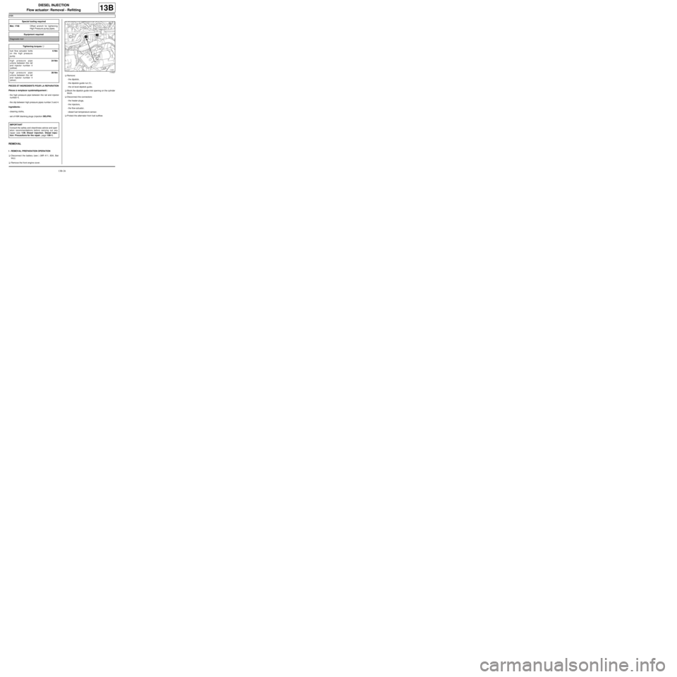
-the dipstick,
-the dipstick guide nut (1) ,
-the oil level dipstick guide.
aBlock the dipstick guide inlet opening on the cylinder
block.
aDisconnect the connectors:
-the heater plugs,
-the injectors,
-the flow actuator,
-diesel fuel temperature sensor.
aProtect the alternator from fuel outflow. Special tooling required
Mot. 1746Offset wrench for tightening
High Pressure pump pipes.
Equipment required
Diagnostic tool
Tightening torquesm
fuel flow actuator bolts
on the high pressure
pump6 Nm
high pressure pipe
unions between the rail
and injector number 4
(yellow)24 Nm
high pressure pipe
unions between the rail
and injector number 4
(silver)28 Nm
IMPORTANT
Consult the safety and cleanliness advice and oper-
ation recommendations before carrying out any
repair (see 13B, Diesel injection, Diesel injec-
tion: Precautions for the repair, page 13B-1) .
114527