RENAULT TWINGO 2009 2.G Engine And Peripherals Repair Manual
Manufacturer: RENAULT, Model Year: 2009, Model line: TWINGO, Model: RENAULT TWINGO 2009 2.GPages: 652
Page 51 of 652
10A-45
ENGINE AND CYLINDER BLOCK ASSEMBLY
Oil pressure sensor: Removal - Refitting
K9K
10A
REMOVAL
I - REMOVAL PREPARATION OPERATION
aPosition the vehicle on a two-post lift ( (see Vehicle:
Towing and lifting) ).
II - OPERATION FOR REMOVAL OF PART
CONCERNED
aDisconnect the oil pressure sensor connector.
aRemove the oil pressure sensor (1) using the (Mot.
1495-01).
REFITTING
I - REFITTING OPERATION FOR PART
CONCERNED
aRefit the oil pressure sensor using the (Mot. 1495-
01).
aTorque tighten the oil pressure sensor (35 Nm).
II - FINAL OPERATION.
aConnect the Diagnostic tool and check for any
faults; deal with them if necessary. Special tooling required
Mot. 1495-0122 mm socket for removal -
refitting of oxygen sensors.
Equipment required
Diagnostic tool
Tightening torquesm
oil pressure sensor35 Nm
113894
Page 52 of 652
10A-46
ENGINE AND CYLINDER BLOCK ASSEMBLY
Oil pressure sensor: Removal - Refitting
D4F, and 772 – D7F
10A
REMOVAL
I - REMOVAL PREPARATION OPERATION
aPosition the vehicle on a two-post lift (see Vehicle:
Towing and lifting) (02A, Lifting equipment).
aDisconnect the oil pressure sensor connector (1) .
II - OPERATION FOR REMOVAL OF PART
CONCERNED
aRemove the oil pressure sensor.
REFITTING
I - REFITTING OPERATION FOR PART
CONCERNED
aRefit the oil pressure sensor.
aTorque tighten the oil pressure sensor (35 N.m).
II - FINAL OPERATION
aConnect the oil pressure sensor connector.Tightening torquesm
oil pressure sensor35 N.m
120772
Page 53 of 652
10A-47
ENGINE AND CYLINDER BLOCK ASSEMBLY
Oil pressure sensor: Removal - Refitting
D4F, and 780 or 782
10A
REMOVAL
I - REMOVAL PREPARATION OPERATION
aPosition the vehicle on a two-post lift (see Vehicle:
Towing and lifting) (02A, Lifting equipment).
aRemove the air filter unit (see 12A, Fuel mixture,
Air filter unit: Removal - Refitting, page 12A-13) .
aUnclip the upstream oxygen sensor wiring harness
from the turbocharger heat shield.
II - OPERATION FOR REMOVAL OF PART
CONCERNED
aDisconnect the oil pressure sensor connector (1) .
aRemove the oil pressure sensor (2) .
REFITTING
REFITTING OPERATION FOR PART CONCERNED
aRefit the oil pressure sensor.
aTorque tighten the oil pressure sensor (35 N.m).
aConnect the oil pressure sensor connector.
aClip the upstream oxygen sensor wiring harness
onto the turbocharger heat shield.aRefit the air filter unit (see 12A, Fuel mixture, Air fil-
ter unit: Removal - Refitting, page 12A-13) .
Tightening torquesm
oil pressure sensor35 N.m
121725
Page 54 of 652
10A-48
ENGINE AND CYLINDER BLOCK ASSEMBLY
Oil pressure sensor: Removal - Refitting
K4M
10A
REMOVAL
I - REMOVAL PREPARATION OPERATION
aRemove:
-the dipstick,
-the dipstick guide bolts (1) .
aMove aside the dipstick guide.aRemove:
-the alternator strut bolts (2) ,
-the alternator strut.
aDisconnect the pinking sensor connector (3) . Tightening torquesm
oil pressure sensor32 N.m
alter nator strut bolts25 N.m
132368
132363
132374
Page 55 of 652
10A-49
ENGINE AND CYLINDER BLOCK ASSEMBLY
Oil pressure sensor: Removal - Refitting
K4M
10A
II - REMOVAL OPERATION
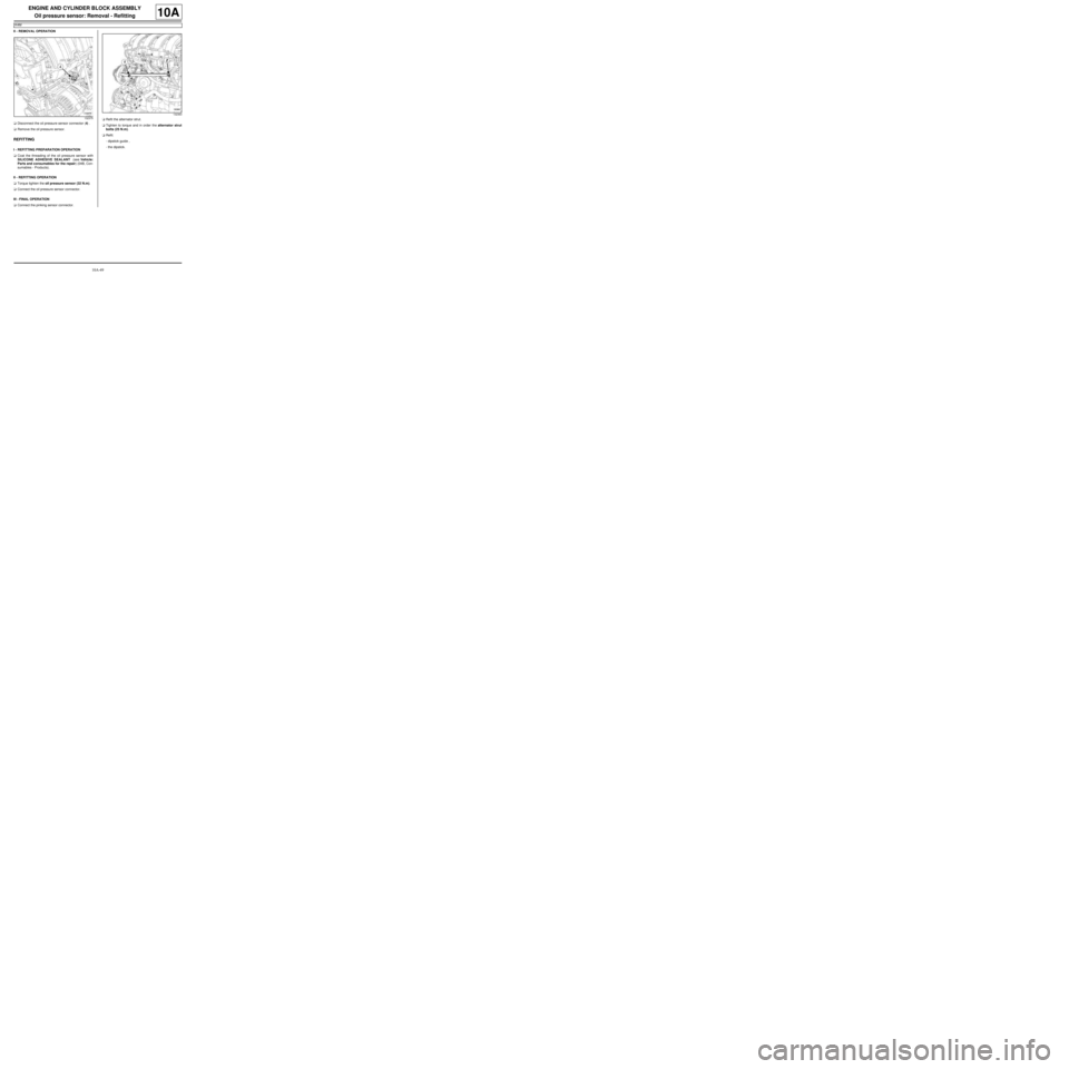
aDisconnect the oil pressure sensor connector (4) .
aRemove the oil pressure sensor.
REFITTING
I - REFITTING PREPARATION OPERATION
aCoat the threading of the oil pressure sensor with
SILICONE ADHESIVE SEALANT (see Vehicle:
Parts and consumables for the repair) (04B, Con-
sumables - Products).
II - REFITTING OPERATION
aTorque tighten the oil pressure sensor (32 N.m).
aConnect the oil pressure sensor connector.
III - FINAL OPERATION
aConnect the pinking sensor connector.aRefit the alternator strut.
aTighten to torque and in order the alternator strut
bolts (25 N.m).
aRefit:
-dipstick guide ,
-the dipstick.
132375
132363
Page 56 of 652
10A-50
ENGINE AND CYLINDER BLOCK ASSEMBLY
Oil pump: Removal - Refitting
K9K
10A
REMOVAL
I - OPERATION FOR REMOVAL OF PART
CONCERNED
aPosition the vehicle on a two-post lift ( (see Vehicle:
Towing and lifting) ).
aDisconnect the battery ( (see Battery: Removal -
Refitting) ).
aRemove the sump (see 10A, Engine and cylinder
block assembly, Lower cover: Removal - Refit-
ting, page 10A-6) .
II - OPERATION FOR REMOVAL OF PART
CONCERNED
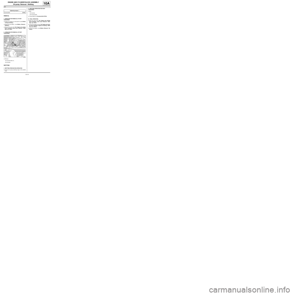
aRemove:
-the oil pump bolts (1) ,
-the oil pump.
REFITTING
I - REFITTING PREPARATION OPERATION
aCheck for oil pump centering rings on the cylinder
block.II - REFITTING OPERATION FOR PART
CONCERNED
aRefit:
-the oil pump,
-the oil pump bolts.
aTorque tighten the oil pump bolts (25 Nm).
III - FINAL OPERATION.
aRefit the sump (see 10A, Engine and cylinder
block assembly, Lower cover: Removal - Refit-
ting, page 10A-6) .
aTop up the engine oil (see 10A, Engine and cylin-
der block assembly, Engine oil: Draining - Refill-
ing, page 10A-22) .
aConnect the battery ( (see Battery: Removal - Re-
fitting) ). Tightening torquesm
oil pump bolts25 Nm
120313
Page 57 of 652
10A-51
ENGINE AND CYLINDER BLOCK ASSEMBLY
Oil pump: Removal - Refitting
D4F or D7F
10A
REMOVAL
I - REMOVAL PREPARATION OPERATION
aPosition the vehicle on a two-post lift (see Vehicle:
Towing and lifting) (02A, Lifting equipment).
aDrain the engine oil (see 10A, Engine and cylinder
block assembly, Engine oil: Draining - Refilling,
page 10A-22) .
aRemove:
-the oil filter (see 10A, Engine and cylinder block
assembly, Oil filter: Removal - Refitting, page
10A-29) ,
-the dipstick,
-the front wheels (see Wheel: Removal - Refitting)
(35A, Wheels and tyres),
-the front wheel arch liners (see Front wheel arch
liner: Removal - Refitting) (55A, Exterior protec-
tion),
-the accessories belt (see 11A, Top and front of
engine, Accessories belt: Removal - Refitting,
page 11A-3) ,
-the engine tie-bar (see 19D, Engine mounting,
Lower engine tie-bar: Removal - Refitting, page
19D-18) ,
-the right-hand suspended engine mounting (see
19D, Engine mounting, Right-hand suspended
engine mounting: Removal - Refitting, page
19D-13) ,-the crankshaft accessories pulley (see 11A, Top
and front of engine, Crankshaft accessories
pulley: Removal - Refitting, page 11A-20) ,
-the timing belt (see 11A, Top and front of engine,
Timing belt: Removal - Refitting, page 11A-27) .
aRefit:
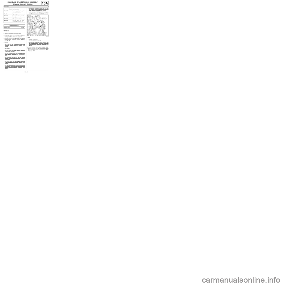
-the upper timing cover,
-the upper timing cover bolts (1) ,
-the right-hand suspended engine mounting (see
19D, Engine mounting, Right-hand suspended
engine mounting: Removal - Refitting, page
19D-13) .
aRemove the lower engine support tool (Mot. 1379).
aRemove the sump (see 10A, Engine and cylinder
block assembly, Lower cover: Removal - Refit-
ting, page 10A-6) . Special tooling required
Mot. 1379Engine suppor t tool for cylin-
der head oper ations.
Ms. 583Pipe clamps .
Mot. 1448Remote operation pliers for
hose clips .
Mot. 1374Oil pump seal e xtractor.
Mot. 1626Tool for fitting the PTFE
cr ankshaft seal, timing end.
Tightening torquesm
oil pump bolts10 N.m
109740
Page 58 of 652
10A-52
ENGINE AND CYLINDER BLOCK ASSEMBLY
Oil pump: Removal - Refitting
D4F or D7F
10A
aDisconnect the oil pressure sensor connector.
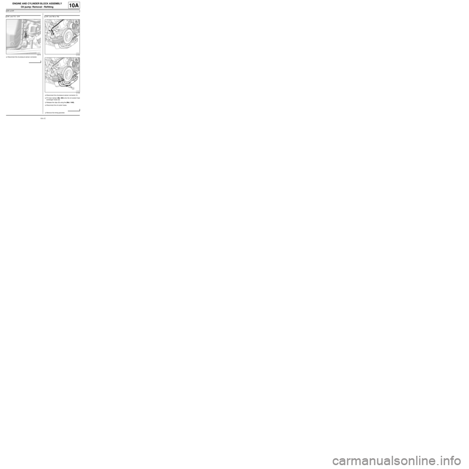
aDisconnect the oil pressure sensor connector (1) .
aFit hose clamps (Ms. 583) onto the oil-coolant heat
exchanger hoses (2) .
aRelease the clips (3) using the (Mot. 1448).
aDisconnect the oil cooler hoses.
aRemove the timing sprocket. D4F, and 772 – D7F
120772
D4F, and 780 or 782
121725
121726
Page 59 of 652
10A-53
ENGINE AND CYLINDER BLOCK ASSEMBLY
Oil pump: Removal - Refitting
D4F or D7F
10A
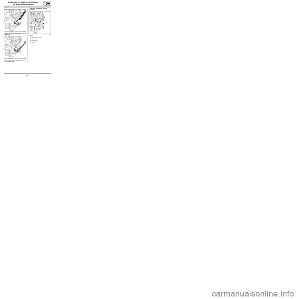
aRemove the crankshaft output seal by turning the
(Mot. 1374).
aRemove the crankshaft output seal by turning the
bolt of the (Mot. 1374).II - OPERATION FOR REMOVAL OF PART
CONCERNED
aRemove:
-the oil pump strainer bolts,
-the oil pump strainer,
-the oil pump bolts,
-the oil pump.
18645-1
18645-2
18646
Page 60 of 652
10A-54
ENGINE AND CYLINDER BLOCK ASSEMBLY
Oil pump: Removal - Refitting
D4F or D7F
10A
REFITTING
I - REFITTING PREPARATION OPERATION
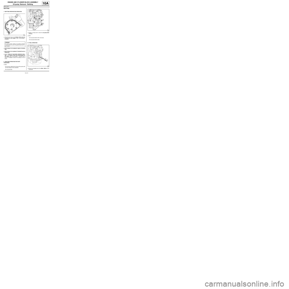
aClean the joint faces (see Vehicle: Parts and con-
sumables for the repair) (04B, Consumables -
Products).
aparts always to be replaced: engine oil strainer
seal.
aparts always to be replaced: Crankshaft seal on
timing end.
aApply a BEAD OF SILICONE ADHESIVE SEAL-
ANT (see Vehicle: Parts and consumables for
the repair) (04B, Consumables - Products) with a
width of 1.3 mm to ensure the sealing of the oil
pump.
II - REFITTING OPERATION FOR PART
CONCERNED
aRefit:
-the oil pump, aligning the oil pump drive points with
the flat surfaces of the crankshaft,
-the oil pump bolts.aTighten to torque and in order the oil pump bolts
(10 N.m).
aRefit:
-the oil pump strainer with a new seal,
-the oil pump strainer bolts.
III - FINAL OPERATION
aScrew the threaded rod of the (Mot. 1626) into the
crankshaft.
18718
WARNING
To ensure proper sealing, the gasket surfaces
must be clean, dry and not greasy (avoid any fin-
ger marks).
18646
20784