check oil RENAULT TWINGO 2009 2.G Engine And Peripherals Repair Manual
[x] Cancel search | Manufacturer: RENAULT, Model Year: 2009, Model line: TWINGO, Model: RENAULT TWINGO 2009 2.GPages: 652
Page 472 of 652

17A-16
IGNITION
Plugs: Removal - Refitting
K4M
17A
Spark plug electrode gap
REMOVAL
I - REMOVAL PREPARATION OPERATION
aRemove the ignition coils (see 17A, Ignition, Coils:
Removal - Refitting, page 17A-1) .
II - OPERATION FOR REMOVAL OF PART
CONCERNED
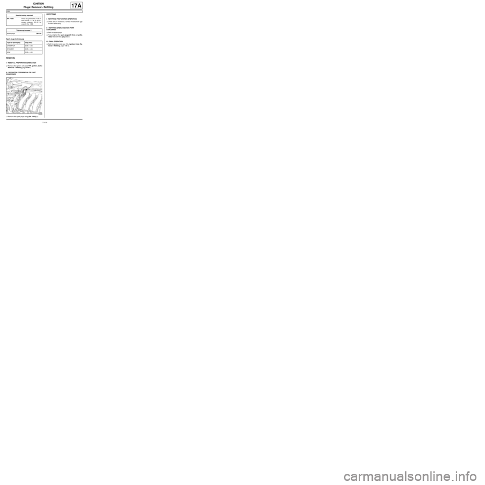
aRemove the spark plugs using (Ele. 1382) (1) .
REFITTING
I - REFITTING PREPARATION OPERATION
aCheck and, if necessary, correct the electrode gap
for each spark plug.
II - REFITTING OPERATION FOR PART
CONCERNED
aRefit the spark plugs.
aTorque tighten the spark plugs (28 N.m) using (Ele.
1382) fitted with the grey sleeve.
III - FINAL OPERATION
aRefit the ignition coils (see 17A, Ignition, Coils: Re-
moval - Refitting, page 17A-1) . Special tooling required
Ele. 1382Set of plug wrenches 16 & 21
mm torque 17.5 & 28 N.m +
square adapter 9-9.52 for
wrench Ele . 1086
Tightening torquesm
spar k plugs28 N.m
Type of spark plug Gap (mm)
CHAMPION 0.95 ± 0.05
EYQUEM 0.95 ± 0.05
NGK 0.95 ± 0.05
132449
Page 520 of 652

19A-10
COOLING
Cooling system: Draining - Refilling
D4F or D7F or K4M or K9K
19A
2 - Filling method without special tools
a
aRemove the air filter unit (see 12A, Fuel mixture,
Air filter unit: Removal - Refitting, page 12A-13) .
aRemove the front engine cover.
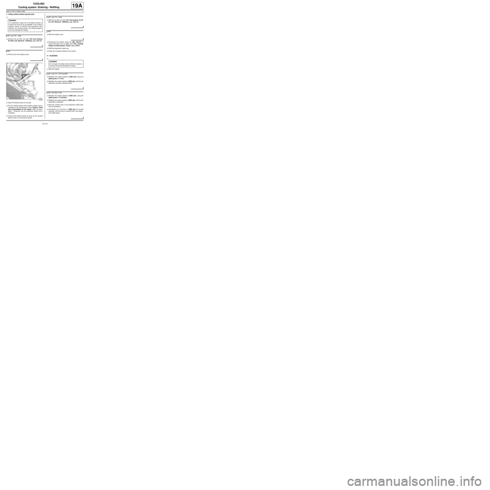
aOpen the bleed screws (1) and (2) .
aFill the cooling system with engine coolant recom-
mended by the manufacturer (see Vehicle: Parts
and consumables for the repair) (04B, Consum-
ables - Products) via the expansion bottle until it
overflows.
aClose all the bleed screws as soon as the coolant
starts to flow in a continuous stream.aRefit the air filter unit (see 12A, Fuel mixture, Air fil-
ter unit: Removal - Refitting, page 12A-13) .
aRefit the engine cover.
aPressurise the system using the (Ms. 554-07) to
check that there are no leaks (see 19A, Cooling,
Engine cooling system: Check, page 19A-2) .
aRefit the expansion bottle cap.
aClean any surfaces soiled by the coolant.
IV - BLEEDING
a
aStart the engine.
aMaintain the engine speed at 2500 rpm using the
pedal press for 5 min.
aStabilise the engine speed at 2000 rpm until the fan
assembly has been activated twice.
aMaintain the engine speed at 2500 rpm, using the
pedal press for 5 minutes.
aStabilise the engine speed at 2000 rpm until the fan
assembly is activated.
aNote the coolant level in the expansion bottle after
this first activation.
aAccelerate at a minimum of 4000 rpm for several
seconds, until the level of coolant fluid in the expan-
sion bottle drops. WARNING
It is essential to open all of the bleed screws to
remove as much as air as possible in the cooling
system. Failure to perform this procedure may
prevent the cooling system from filling properly
and may damage the engine.
D4F, and 772 – K4M
K9K
120526
D4F, and 772 – K4M
K9K
WARNING
Do not open the bleed screw whilst the engine is
running; this would damage the engine.
D4F, and 772 – D7F, and 800
D4F, and 780 or 782
Page 527 of 652

19A-17
COOLING
Cooling radiator: Removal - Refitting
K9K
19A
-the top hose on the radiator,
-the bottom hose on the radiator.
a
aLubricate the seals with the recommended air condi-
tioning oil to facilitate fitting.
aFit the condenser connecting pipes.
aFit the connecting pipe unions to the condenser.
aRefit the plastic cover on the condenser.
aConnect the pressostat connector.
aRefit:
-the front bumper (see Front bumper: Removal -
Refitting) (55A, Exterior protection),
-the front wheel arch liners (see Front wheel arch
liner: Removal - Refitting) (55A, Exterior protec-
tion),
-the front wheels (see Wheel: Removal - Refitting)
(35A, Wheels and tyres).
aConnect the battery (see ) (80A, Battery).
aFill and bleed the cooling system (see 19A, Cool-
ing, Cooling system: Draining - Refilling, page
19A-9) .aCheck that the system is operating correctly (see Air
conditioning: Check) (62A, Air conditioning).
aFill the refrigerant circuit using a refrigerant charg-
ing station (see Refrigerant circuit: Draining -
Filling) (62A, Air conditioning).
aCheck the refrigerant circuit (see Refrigerant cir-
cuit: Check) (62A, Air conditioning). AIR CONDITIONING
WARNING
Do not remove the blanking plugs from each
component until the last moment.
Also, do not remove the components from their
packaging until they are to be fitted to the vehi-
cle.
WARNING
To avoid any leaks, check that the seal and the
pipe surface are in good condition. The seal and
the surface must be clean and scratch free.
AIR CONDITIONING
Page 596 of 652

19B-14
EXHAUST
Catalytic converter: Removal - Refitting
K9K
19B
aIf they are replaced, torque tighten the catalytic
converter studs on the turbocharger (9 Nm ).
II - REFITTING OPERATION FOR PART
CONCERNED
aFrom underneath the vehicle, fit:
-the catalytic converter on the turbocharger fitted
with a new seal between the catalytic converter
and the turbocharger,
-one of the catalytic converter nuts on the turbo-
charger.
aIn order, fit (without tightening):
-the catalytic converter upstream strut bolts on the
engine,
-the catalytic converter downstream strut bolt and
nut on the gearbox,
-the catalytic converter upstream strut bolts on the
catalytic converter,
-the catalytic converter downstream strut bolt on the
catalytic converter,
-the catalytic converter nuts on the turbocharger,
aTorque tighten and in order:
-the catalytic converter nuts on the turbocharger
(26 Nm),
-the catalytic converter upstream strut bolts on
the engine (44 Nm),
-the catalytic converter downstream strut bolts
on the gearbox (21 Nm),
-the catalytic converter downstream strut nut on
the gearbox (21 Nm),
-the catalytic converter upstream strut bolts on
the catalytic converter (26 Nm),
-the catalytic converter downstream strut bolt
on the catalytic converter (21 Nm).
aFit in order:
-a new exhaust system sealing ring on the catalytic
converter,
-the exhaust pipe on the catalytic converter,
-the exhaust pipe springs and bolts on the catalytic
converter.aTorque tighten the exhaust pipe bolts on the cata-
lytic converter (21 Nm).
aCheck the following and deal with if necessary:
-that there is no contact with the underbody,
-the presence and correct positioning of all the ex-
haust pipe heat shields.
III - FINAL OPERATION.
aRefit:
-the engine tie-bar (see 19D, Engine mounting,
Lower engine tie-bar: Removal - Refitting, page
19D-18) ,
-the air filter box (see 12A, Fuel mixture, Air filter
unit: Removal - Refitting, page 12A-13) ,
-the scoop under the scuttle panel grille ( (see
Scoop under the scuttle panel grille: Removal -
Refitting) ),
-the scuttle panel grille ( (see Scuttle panel grille:
Removal - Refitting) ),
-the windscreen wiper arms ( (see Windscreen
wiper arm: Removal - Refitting) ).
aConnect the battery ( (see Battery: Removal - Re-
fitting) ).
aStart the engine.
aCheck that there are no leaks and deal with them if
necessary. Note:
Check that there is no contact between the cata-
lytic conver ter and the turbocharger oil return
pipe during the entire catalytic converter tighten-
ing operation.