RENAULT TWINGO 2009 2.G Engine And Peripherals Repair Manual
TWINGO 2009 2.G
RENAULT
RENAULT
https://www.carmanualsonline.info/img/7/1710/w960_1710-0.png
RENAULT TWINGO 2009 2.G Engine And Peripherals Repair Manual
Page 484 of 652
17B-9
PETROL INJECTION
Petrol injection: List and location of components
K4M
17B
131776
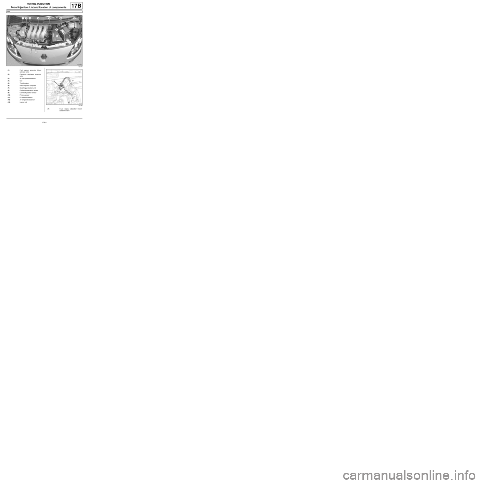
(1) Fuel vapour absorber bleed
solenoid valve
(2) Camshaft dephaser solenoid
valve
(3) Air inlet pressure sensor
(4) Coil
(5) Throttle valve
(6) Petrol injection computer
(7) Switching protection unit
(8) Coolant temper ature sensor
(9) Camshaft position sensor
(10) Pinking sensor
(11) Oil pressure sensor
(12) Air temperature sensor
(13) Injector rail
131766
(1) Fuel vapour absorber bleed
solenoid valve
Page 485 of 652
17B-10
PETROL INJECTION
Petrol injection: List and location of components
K4M
17B
132443
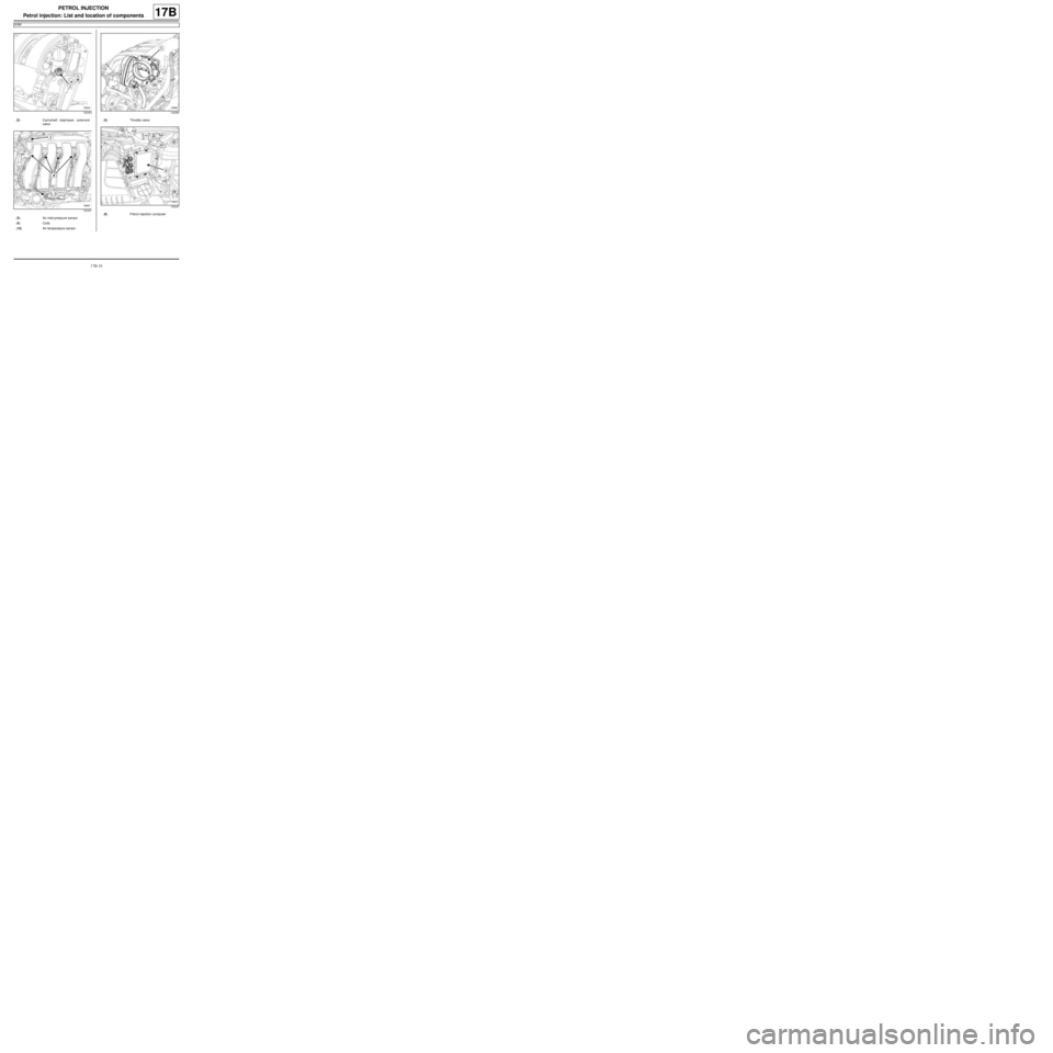
(2) Camshaft dephaser solenoid
valve
132431
(3) Air inlet pressure sensor
(4) Coils
(12) Air temperature sensor
132383
(5) Throttle valve
132447
(6) Petrol injection computer
Page 486 of 652
17B-11
PETROL INJECTION
Petrol injection: List and location of components
K4M
17B
119373
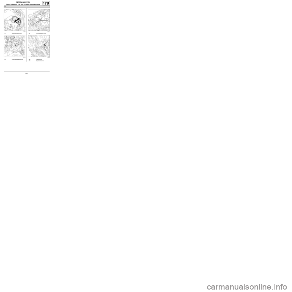
(7) Switching protection unit
131762
(8) Coolant temper ature sensor
132391
(9) Camshaft position sensor
132374
(10) Pinking sensor
(11) Oil pressure sensor
Page 555 of 652
19A-45
COOLING
Water chamber: Removal - Refitting
K9K
19A
II - REFITTING OPERATION FOR PART
CONCERNED
aRefit the thermostat to the water chamber.
aRefit:
-a new water chamber seal,
-the water chamber.
aTorque tighten the water chamber bolts (10 N.m).
III - FINAL OPERATION
aConnect the cooling hoses on the water chamber.
aPosition the cooling hose clips on the water chamber
using the tool (Mot. 1448).
aClip on the cooling hose of the coolant-oil heat ex-
changer.
aConnect the intercooler air outlet pipe on the side of
the damper valve.
aTorque tighten the intercooler air outlet pipe clip
at the damper valve end (5.5 N.m).
aConnect the brake servo vacuum pipe.
aClip:
-the turbocharging pressure regulator vacuum pipe,
-the vacuum pipe from the brake servo.
aConnect the turbocharging pressure regulator vacu-
um pipe.
aRefit the nuts of the air hoses on the lifting eye.
aConnect the intercooler air inlet pipe at the turbo-
charger end.
aClip on the intercooler air inlet pipe clip at the turbo-
charger end.
aFill the cooling system (see 19A, Cooling, Cooling
system: Draining - Refilling, page 19A-9) .
aRefit the engine cover. K9K, and 718
Page 572 of 652
19A-62
COOLING
Coolant pump inlet pipe: Removal - Refitting
K4M
19A
REMOVAL
I - REMOVAL PREPARATION OPERATION
aPosition the vehicle on a two-post lift (see Vehicle:
Towing and lifting) (02A, Lifting equipment).
aDisconnect the battery (see ) (80A, Battery).
aRemove the engine undertray.
aDrain the cooling system (see 19A, Cooling, Cool-
ing system: Draining - Refilling, page 19A-9) .
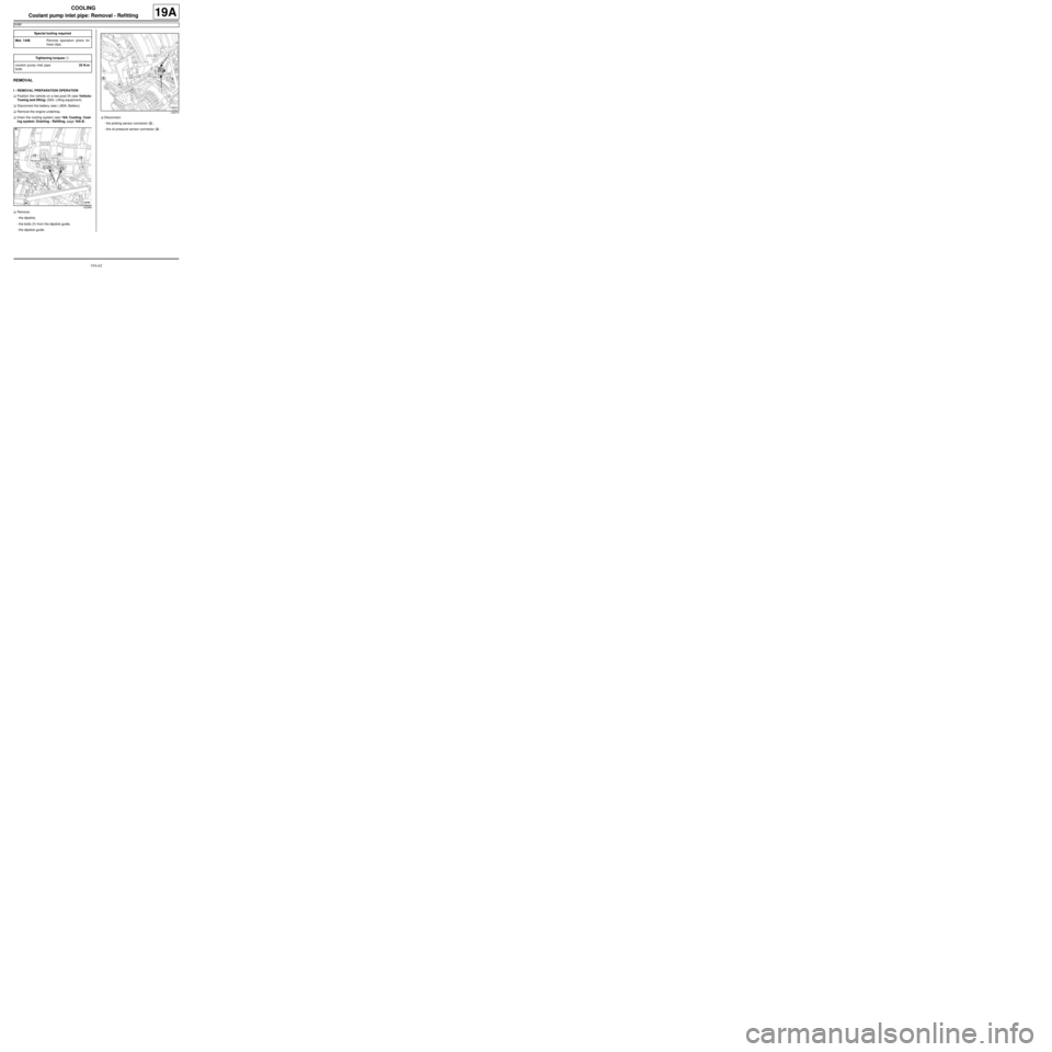
aRemove:
-the dipstick,
-the bolts (1) from the dipstick guide,
-the dipstick guide.aDisconnect:
-the pinking sensor connector (2) ,
-the oil pressure sensor connector (3) . Special tooling required
Mot. 1448Remote operation pliers for
hose clips .
Tightening torquesm
coolant pump inlet pipe
bolts25 N.m
132368
132374
Page 573 of 652
19A-63
COOLING
Coolant pump inlet pipe: Removal - Refitting
K4M
19A
II - REMOVAL OPERATION
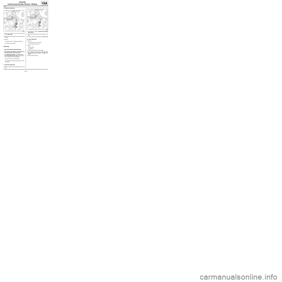
aRemove the clip (4) from each cooling hose using
the tool (Mot. 1448).
aDisconnect the cooling hoses from the coolant pump
inlet pipe.
aRemove:
-the bolts (5) from the coolant pump inlet pipe,
-the coolant pump inlet pipe.
REFITTING
I - REFITTING PREPARATION OPERATION
aparts always to be replaced: seal between cool-
ant pump inlet pipe and coolant pump.
aUse SURFACE CLEANER (see Vehicle: Parts
and consumables for the repair) (04B, Consuma-
bles - Products) to clean and degrease:
-the seal housing in the cylinder block,
-the coolant pump inlet pipe seal housing if it is be-
ing reused.
II - REFITTING OPERATION
aRefit the coolant pump inlet pipe fitted with a new
seal.aTorque tighten in order the coolant pump inlet pipe
bolts (25 N.m).
aConnect the cooling hoses to the coolant pump inlet
pipe.
aFit each cooling hose clip using the tool (Mot. 1448).
III - FINAL OPERATION
aConnect:
-the oil pressure sensor connector,
-the pinking sensor connector.
aRefit:
-dipstick guide ,
-the dipstick.
aConnect the battery (see ) (80A, Battery).
aFill and bleed the cooling system (see 19A, Cool-
ing, Cooling system: Draining - Refilling, page
19A-9) .
aRefit the engine undertray.
131781
131781
