fuel pressure RENAULT TWINGO 2009 2.G Engine And Peripherals Manual PDF
[x] Cancel search | Manufacturer: RENAULT, Model Year: 2009, Model line: TWINGO, Model: RENAULT TWINGO 2009 2.GPages: 652
Page 436 of 652
14A-18
ANTIPOLLUTION
Exhaust gas recirculation assembly: Removal - Refitting
K9K
14A
aRefit:
-new seals on the coolant circulation cover,
-the coolant circulation cover on the exhaust gas
cooler.
aTorque tighten the coolant circulation cover bolts
on the exhaust gas cooler (12 N.m).
aRemove the tool (Ms. 583) from the coolant inlet and
outlet hoses of the exhaust gas cooler.
III - FINAL OPERATION
aFit the intercooler air outlet pipe at the damper valve
end.
aConnect the intercooler air outlet pipe on the side of
the damper valve.
aTorque tighten the intercooler air outlet pipe clip
at the damper valve end (5.5 N.m).
aRefit the intercooler air outlet pipe nut on the lifting
eye.
aConnect the turbocharging pressure regulator vacu-
um pipe.
aClip:
-the turbocharging pressure regulator vacuum pipe,
-the vacuum pipe from the brake servo.
aConnect the brake servo vacuum pipe.
aFit the intercooler air inlet pipe at the turbocharger
end.
aRefit the intercooler air inlet pipe nut at the turbo-
charger end on the lifting eye.
aConnect the intercooler air inlet pipe at the turbo-
charger end.
aClip on the intercooler air inlet pipe clip at the turbo-
charger end.
aRefit the air outlet pipe onto the air filter unit.
aTighten the air filter unit air outlet pipe clip on the tur-
bocharger.
aConnect the oil vapour rebreathing pipe.
aRefit:
-the exhaust gas recirculation rigid pipe (see 14A,
Antipollution, Exhaust gas recirculation rigid
pipe: Removal - Refitting, page 14A-19) ,-the catalytic converter (see 19B, Exhaust, Cata-
lytic converter: Removal - Refitting, page 19B-
12) ,
-the lower engine tie-bar (see 19D, Engine mount-
ing, Lower engine tie-bar: Removal - Refitting,
page 19D-18) ,
-the EGR solenoid valve (see 14A, Antipollution,
Exhaust gas recirculation solenoid valve: Re-
moval - Refitting, page 14A-10) ,
-the air filter unit (see 12A, Fuel mixture, Air filter
unit: Removal - Refitting, page 12A-13) ,
-the scoop under the scuttle panel grille (see Scoop
under the scuttle panel grille: Removal - Refit-
ting) (56A, Exterior equipment).
-the scuttle panel grille (see Scuttle panel grille:
Removal - Refitting) (56A, Exterior equipment),
-the windscreen wiper arms (see Windscreen wip-
er arm: Removal - Refitting) (85A, Wiping -
Washing),
aConnect the battery (see ) (80A, Battery).
aFill and bleed the cooling system (see 19A, Cool-
ing, Cooling system: Draining - Refilling, page
19A-9) .
aRefit the engine cover. K9K, and 718
Page 480 of 652
17B-5
PETROL INJECTION
Petrol injection: List and location of components
D4F, and 780 or 782
17B
122387
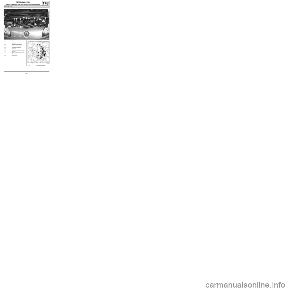
(1) Fuel vapour recirculation sole-
noid valve
(2) Upstream oxygen sensor
(3) Petrol injection computer
(4) Motorised throttle valve
(5) Ignition coil
(6) Engine compar tment connec-
tion unit
(7) Intake distributor pressure sen-
sor
(8) Turbocharger
108254
(9) Fuel injection computer
Page 484 of 652
17B-9
PETROL INJECTION
Petrol injection: List and location of components
K4M
17B
131776
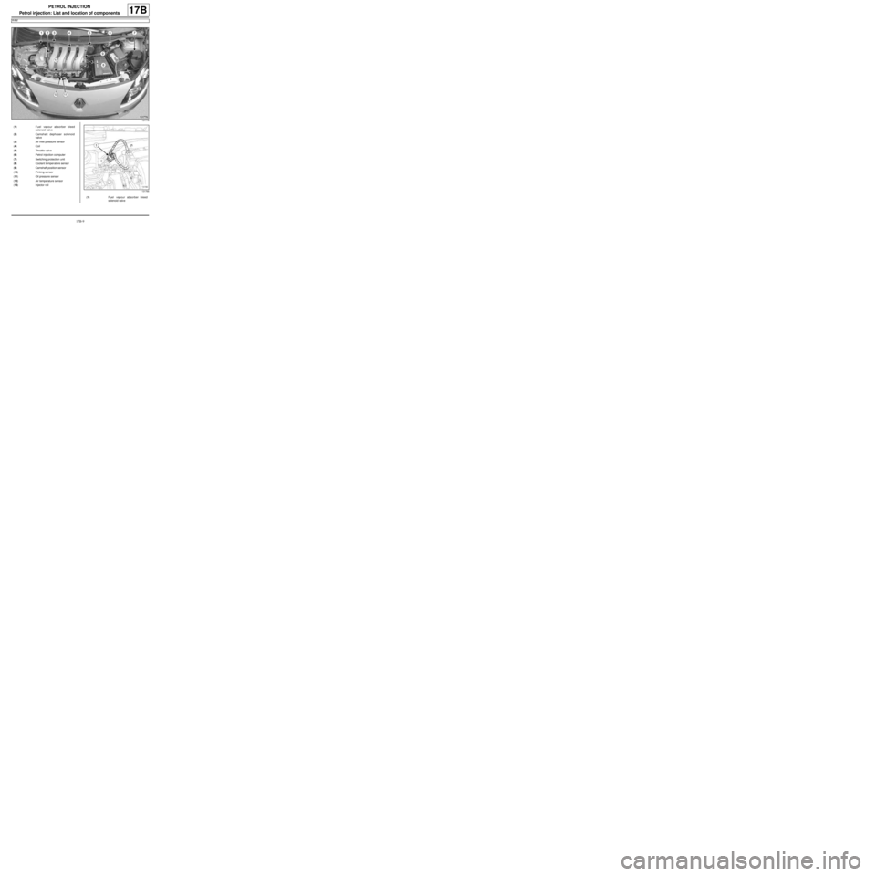
(1) Fuel vapour absorber bleed
solenoid valve
(2) Camshaft dephaser solenoid
valve
(3) Air inlet pressure sensor
(4) Coil
(5) Throttle valve
(6) Petrol injection computer
(7) Switching protection unit
(8) Coolant temper ature sensor
(9) Camshaft position sensor
(10) Pinking sensor
(11) Oil pressure sensor
(12) Air temperature sensor
(13) Injector rail
131766
(1) Fuel vapour absorber bleed
solenoid valve
Page 553 of 652
19A-43
COOLING
Water chamber: Removal - Refitting
K9K
19A
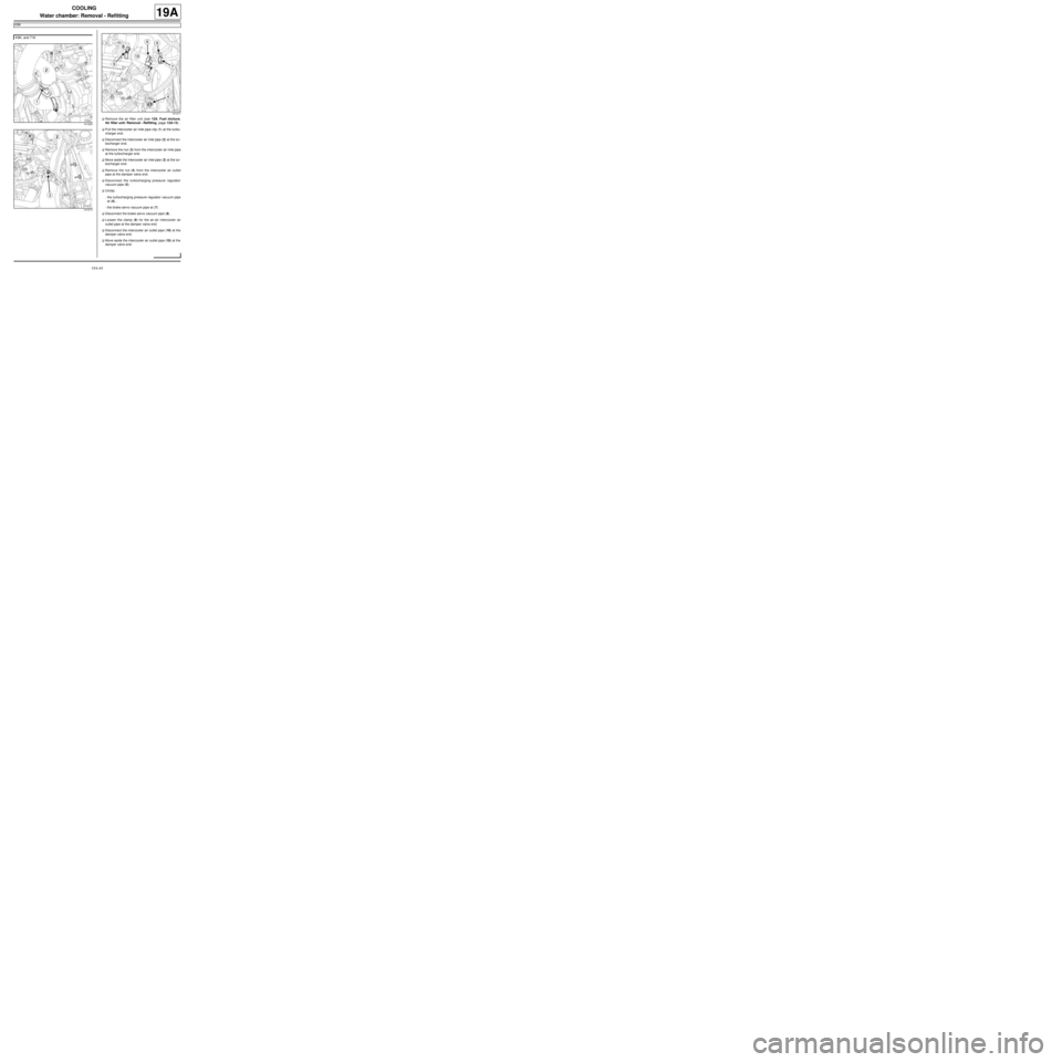
aRemove the air filter unit (see 12A, Fuel mixture,
Air filter unit: Removal - Refitting, page 12A-13) .
aPull the intercooler air inlet pipe clip (1) at the turbo-
charger end.
aDisconnect the intercooler air inlet pipe (2) at the tur-
bocharger end.
aRemove the nut (3) from the intercooler air inlet pipe
at the turbocharger end.
aMove aside the intercooler air inlet pipe (2) at the tur-
bocharger end.
aRemove the nut (4) from the intercooler air outlet
pipe at the damper valve end.
aDisconnect the turbocharging pressure regulator
vacuum pipe (5) .
aUnclip:
-the turbocharging pressure regulator vacuum pipe
at (6) ,
-the brake servo vacuum pipe at (7) .
aDisconnect the brake servo vacuum pipe (8) .
aLoosen the clamp (9) for the air-air intercooler air
outlet pipe at the damper valve end.
aDisconnect the intercooler air outlet pipe (10) at the
damper valve end.
aMove aside the intercooler air outlet pipe (10) at the
damper valve end. K9K, and 718
141222
141213
141217
Page 644 of 652
19D-14
ENGINE MOUNTING
Right-hand suspended engine mounting: Removal - Refitting
C44, and K9K
19D
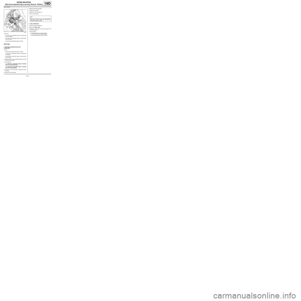
aRemove:
-the right-hand suspended engine mounting bolts
(3) on the engine,
-the right-hand suspended engine mounting bolts
(4) on the body,
-the right-hand suspended engine mounting.
REFITTING
I - REFITTING OPERATION FOR PART
CONCERNED
aRefit:
-the right-hand suspended engine mounting,
-the right-hand suspended engine mounting bolts
on the body,
-the right-hand suspended engine mounting bolts
on the engine.
aTighten all bolts on the suspended engine mounting
until they make contact.
aTorque tighten:
-the right-hand suspended engine mounting
bolts on the engine (62 Nm),
-the right-hand suspended engine mounting
bolts on the body ( 62 Nm).
aFit the clip to the right-hand suspended engine
mounting.
aPosition the fuel filter cage.aRefit the fuel filter cage bolts.
aPosition the fuel filter.
aTighten the fuel filter cage nut.
aClip on the fuel pipes.
II - FINAL OPERATION.
aRefit the expansion bottle bolt.
aRemove the (Mot. 1672).
aTighten the new bolts on the axle sub-frame until
they make contact.
aTorque tighten:
-the axle sub-frame front bolts (62 Nm),
-the axle sub-frame rear bolts (105 Nm).
120047
Note:
Make sure that the clip on the high pressure
pump side is proper ly clipped onto the right-hand
suspended engine mounting.