check engine RENAULT TWINGO 2009 2.G Engine Diesel Injection Workshop Manual
[x] Cancel search | Manufacturer: RENAULT, Model Year: 2009, Model line: TWINGO, Model: RENAULT TWINGO 2009 2.GPages: 269
Page 219 of 269
13B-219V6 MR-413-X44-13B000$190.mif
DIESEL INJECTION
Fault finding – Tests13B
DCM 1.2 Injection
Program No.: 4D
Vdiag No.: 48, 4C, 50,
54, 58, 5C
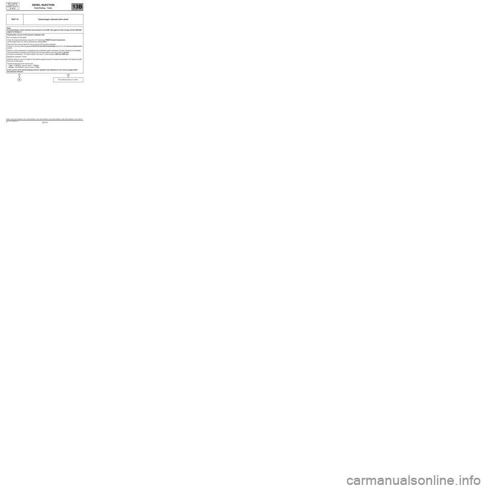
TEST 10 Turbocharger solenoid valve check
Note:
No turbocharger control solenoid valve present on the K9K 740 engine for New Twingo and the K9K 800
engine for Kangoo 2.
Checking the vacuum at the pressure regulator inlet
Run the engine at idle speed.
Check the engine temperature using the CLIP parameter PR064 Coolant temperature.
Let the engine warm up until the temperature reaches 80
°C.
Disconnect the vacuum pipe from the end piece of the pressure regulator.
Connect a vacuum pressure gauge to the end of the disconnected pipe and put it in the vacuum measurement
position.
Perform a quick acceleration by depressing the accelerator pedal completely and then releasing it immediately.
The total duration of pressing and holding in the full load position must not exceed 1 second.
During this acceleration, the engine speed must reach a value between 3000 and 4000 rpm.
Repeat the operation 3 times.
Read the maximum vacuum posted by the pressure gauge during the increase and decrease in the speed and after
the return to idle speed.
Tolerance intervals for the vacuum are:
–1 bar < CORRECT vacuum value < - 0.6 bar
–0.6 bar < INCORRECT vacuum value < 0 bar
Is the vacuum at the turbocharging pressure regulator inlet displayed on the vacuum gauge within
the tolerance interval?
The solenoid valve is in order.
NOYES
A
DCM1.2_V48_TEST10/DCM1.2_V4C_TEST10/DCM1.2_V50_TEST10/DCM1.2_V54_TEST10/DCM1.2_V58_TEST10/DCM1.2_V5C_TEST10
Page 220 of 269
13B-220V6 MR-413-X44-13B000$190.mif
DIESEL INJECTION
Fault finding – Tests13B
DCM 1.2 Injection
Program No.: 4D
Vdiag No.: 48, 4C, 50,
54, 58, 5C
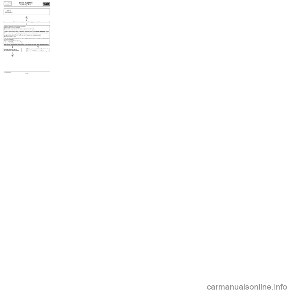
TEST 10
CONTINUED 1
Reconnect the vacuum pipe on the turbocharging pressure regulator
Checking the vacuum at the solenoid valve outlet
Leave the engine running at idle speed.
Disconnect the vacuum pipe from the end piece of the solenoid valve outlet.
This pipe connects the solenoid valve to the turbocharging pressure regulator.
Connect a vacuum pressure gauge to the solenoid valve outlet and put it in the vacuum measurement position.
Perform a quick acceleration by depressing the accelerator pedal completely and then releasing it immediately.
The total duration of pressing and holding in the full load position must not exceed 1 second.
During this acceleration, the engine speed must reach a value between 3000 and 4000 rpm.
Repeat the operation 3 times.
Read the maximum vacuum posted by the pressure gauge during the increase and decrease in the speed and after
the return to idle speed.
Tolerance intervals for the vacuum are:
–1 bar < CORRECT vacuum value < - 0.6 bar
–0.6 bar < INCORRECT vacuum value < 0 bar
Is the vacuum displayed by the pressure gauge at the solenoid valve outlet within the tolerance interval?
Reconnect the vacuum pipe on
the turbocharging pressure regulator Replace the vacuum pipe between the solenoid valve
and the turbocharging pressure regulator (see
Mechanical MR of the vehicle, 12B turbocharging).
A
NOYES
B
Page 221 of 269
13B-221V6 MR-413-X44-13B000$190.mif
DIESEL INJECTION
Fault finding – Tests13B
DCM 1.2 Injection
Program No.: 4D
Vdiag No.: 48, 4C, 50,
54, 58, 5C
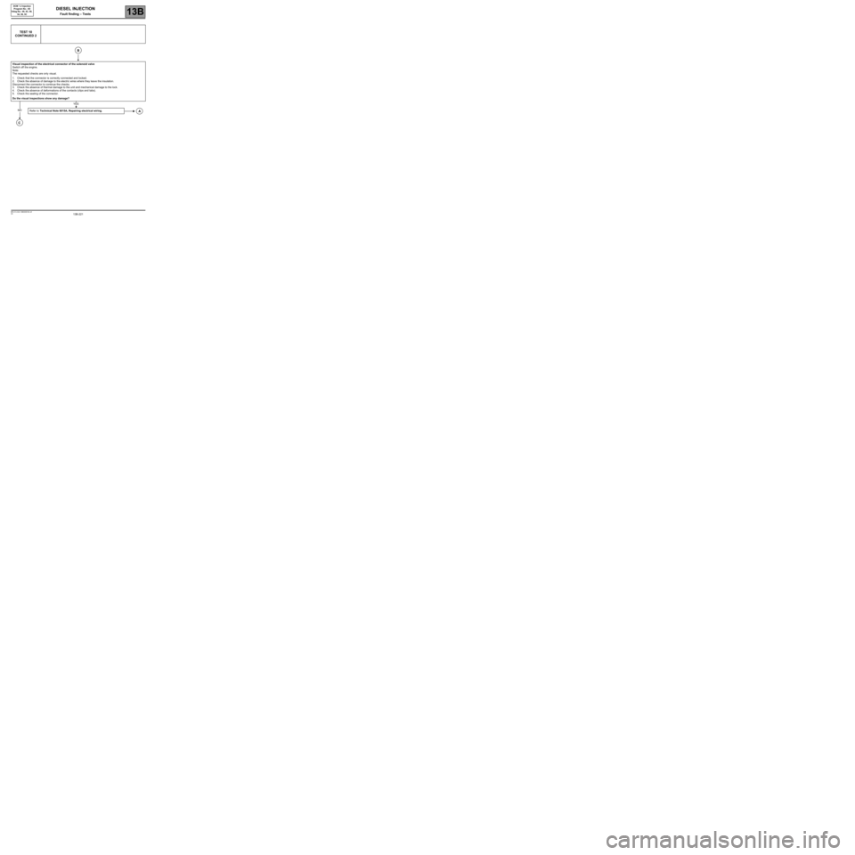
TEST 10
CONTINUED 2
Visual inspection of the electrical connector of the solenoid valve
Switch off the engine.
Note:
The requested checks are only visual.
1. Check that the connector is correctly connected and locked.
2. Check the absence of damage to the electric wires where they leave the insulation.
Disconnect the connector to continue the checks.
3. Check the absence of thermal damage to the unit and mechanical damage to the lock.
4. Check the absence of deformations of the contacts (clips and tabs).
5. Check the sealing of the connector.
Do the visual inspections show any damage?
Refer to Technical Note 6015A, Repairing electrical wiring.
B
NO
YES
A
C
Page 222 of 269
13B-222V6 MR-413-X44-13B000$190.mif
DIESEL INJECTION
Fault finding – Tests13B
DCM 1.2 Injection
Program No.: 4D
Vdiag No.: 48, 4C, 50,
54, 58, 5C
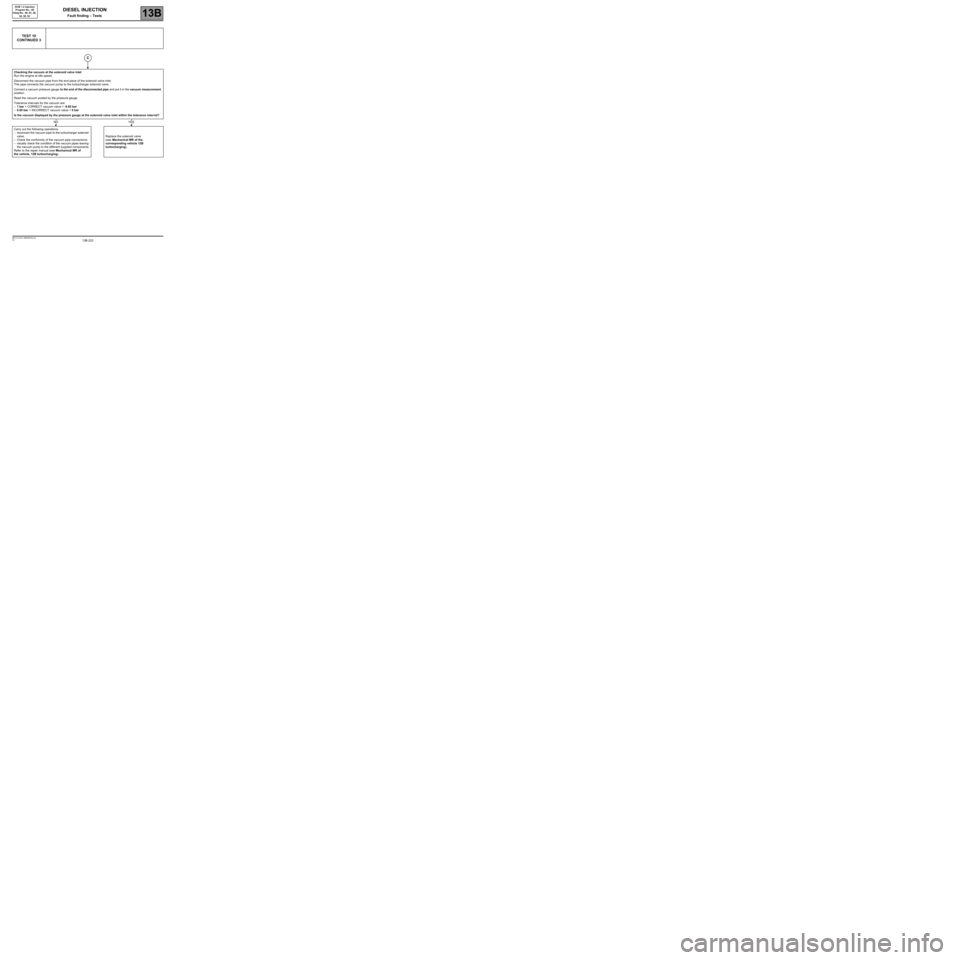
TEST 10
CONTINUED 3
Checking the vacuum at the solenoid valve inlet
Run the engine at idle speed.
Disconnect the vacuum pipe from the end piece of the solenoid valve inlet.
This pipe connects the vacuum pump to the turbocharger solenoid valve.
Connect a vacuum pressure gauge to the end of the disconnected pipe and put it in the vacuum measurement
position.
Read the vacuum posted by the pressure gauge.
Tolerance intervals for the vacuum are:
–1 bar < CORRECT vacuum value < -0.85 bar
–0.85 bar < INCORRECT vacuum value < 0 bar
Is the vacuum displayed by the pressure gauge at the solenoid valve inlet within the tolerance interval?
Carry out the following operations.
–reconnect the vacuum pipe to the turbocharger solenoid
valve.
–Check the conformity of the vacuum pipe connections.
–visually check the condition of the vacuum pipes leaving
the vacuum pump to the different supplied components.
Refer to the repair manual (see Mechanical MR of
the vehicle, 12B turbocharging).Replace the solenoid valve
(see Mechanical MR of the
corresponding vehicle 12B
turbocharging).
C
NOYES
Page 224 of 269
13B-224V6 MR-413-X44-13B000$190.mif
DIESEL INJECTION
Fault finding – Tests13B
DCM 1.2 Injection
Program No.: 4D
Vdiag No.: 48, 4C, 50,
54, 58, 5C
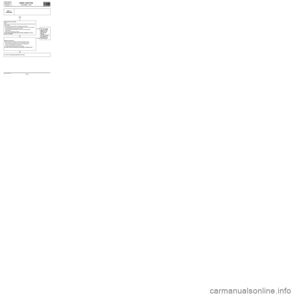
TEST 11
CONTINUED
High pressure circuit check
Note:
Depending on the vehicle type, the best visual access will be either from above
or from below.
Visually inspect the condition of the following components:
–compressor outlet pipe to the turbocharging air cooler (on some engines,
the turbocharging air cooler does not exist),
–outlet pipe of the turbocharging air cooler to the inlet manifold,
–inlet manifold,
–pressure and temperature sensors.
Is one of these components incorrect (pipes dislodged, torn, bent,
pierced or kinked)?Replace the faulty
parts (see MR 364
(Mégane II), 370
(Scénic II), 392
(Clio III), 385
(Modus),
411 (New Twingo) or
417 (Kangoo II),
Mechanical, 12B
Turbocharging).
Exhaust circuit check
Visually inspect the condition of the following engine sections:
–from the exhaust manifold circuit to the turbocharger turbine,
–from the turbine outlet pipe to the end of the exhaust pipe,
–from the inlet manifold to the EGR valve,
–pressure and temperature sensors connected.
Do certain of these components have blackish or whitish traces?
Run test 10 Turbocharger solenoid valve check.
A
YES
NO
YES
NO
Page 225 of 269
13B-225V6 MR-413-X44-13B000$190.mif
DIESEL INJECTION
Fault finding – Tests13B
DCM 1.2 Injection
Program No.: 4D
Vdiag No.: 48, 4C, 50,
54, 58, 5C
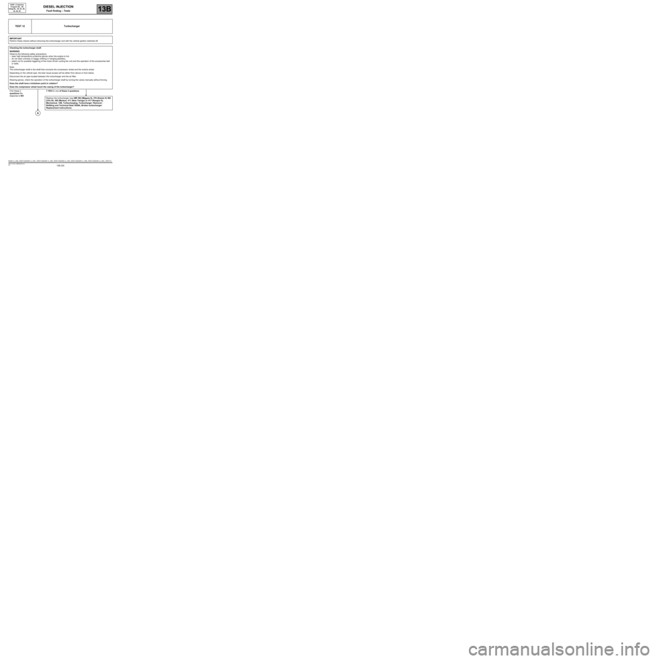
TEST 12 Turbocharger
IMPORTANT
Perform these checks without removing the turbocharger and with the vehicle ignition switched off.
Checking the turbocharger shaft
WARNING
Observe the following safety precautions:
–wear high temperature protective gloves when the engine is hot,
–do not wear oversize or baggy clothing or hanging jewellery,
–watch out for possible triggering of the motor-driven cooling fan unit and the operation of the accessories belt
or belts.
Note:
The turbocharger shaft is the shaft that connects the compressor wheel and the turbine wheel.
Depending on the vehicle type, the best visual access will be either from above or from below.
Disconnect the air pipe located between the turbocharger and the air filter.
Wearing gloves, check the operation of the turbocharger shaft by turning the vanes manually without forcing.
Does the shaft have a kickdown point in rotation?
Does the compressor wheel touch the casing of the turbocharger?
If for these 2
questions the
response is NOIf YES for one of these 2 questions
Replace the turbocharger (see MR 364 (Mégane II), 370 (Scénic II) 392
(Clio III), 385 (Modus), 411 (New Twingo) or 417 (Kangoo II),
Mechanical, 12B, Turbocharging, Turbocharger: Removal -
Refitting and Technical Note 3938A, Broken turbocharger:
Replacement instructions).
A
DCM1.2_V48_TEST12/DCM1.2_V4C_TEST12/DCM1.2_V50_TEST12/DCM1.2_V54_TEST12/DCM1.2_V58_TEST12/DCM1.2_V5C_TEST12
Page 235 of 269
13B-235V6 MR-413-X44-13B000$200.mif
13B
DCM 1.2 Injection
Program No.: 4D
Vdiag No.: 48, 4C, 50,
54, 58, 5C
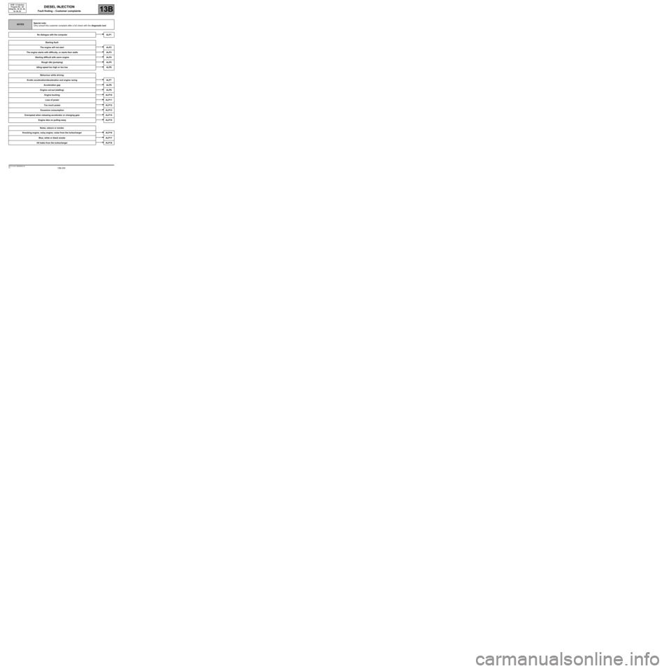
NOTESSpecial note:
Only consult this customer complaint after a full check with the diagnostic tool.
No dialogue with the computer ALP1
Starting fault:
The engine will not start ALP2
The engine starts with difficulty, or starts then stalls ALP3
Starting difficult with warm engine ALP4
Rough idle (pumping) ALP5
Idling speed too high or too low ALP6
Behaviour while driving:
Erratic acceleration/deceleration and engine racing ALP7
Acceleration gap ALP8
Engine cut-out (stalling) ALP9
Engine bucking ALP10
Loss of power ALP11
Too much power ALP12
Excessive consumption ALP13
Overspeed when releasing accelerator or changing gear ALP14
Engine dies on pulling away ALP15
Noise, odours or smoke:
Knocking engine, noisy engine, noise from the turbocharger ALP16
Blue, white or black smoke ALP17
Oil leaks from the turbocharger ALP18
DIESEL INJECTION
Fault finding – Customer complaints
Page 236 of 269
13B-236V6 MR-413-X44-13B000$210.mif
13B
DCM 1.2 Injection
Program No.: 4D
Vdiag No.: 48, 4C, 50,
54, 58, 5C
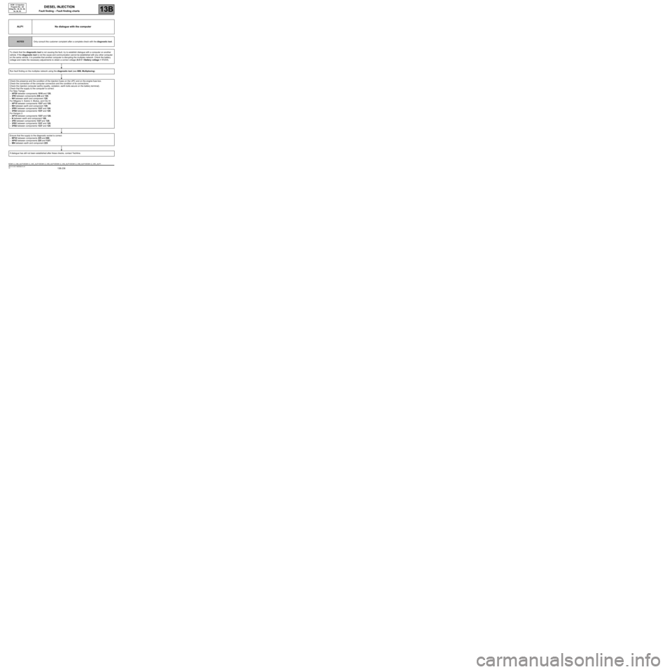
ALP1 No dialogue with the computer
NOTESOnly consult this customer complaint after a complete check with the diagnostic tool.
To check that the diagnostic tool is not causing the fault, try to establish dialogue with a computer on another
vehicle. If the diagnostic tool is not the cause and communication cannot be established with any other computer
on the same vehicle, it is possible that another computer is disrupting the multiplex network. Check the battery
voltage and make the necessary adjustments to obtain a correct voltage (9.5 V < Battery voltage < 17.5 V).
Run fault finding on the multiplex network using the diagnostic tool (see 88B, Multiplexing).
Check the presence and the condition of the injection fuses on the UPC and on the engine fuse box.
Check the connection of the computer connectors and the condition of its connections.
Check the injection computer earths (quality, oxidation, earth bolts secure on the battery terminal).
Check that the supply to the computer is correct:
For New Twingo:
–AP29 between components 1016 and 120,
–3FB between components 238 and 120,
–NH between earth and component 120,
For Mégane II, Scénic II, Modus, and Clio III:
–AP15 between components 1337 and 120,
–NH between earth and component 120,
–3FB1 between components 1337 and 120,
–3FB2 between components 1337 and 120.
For Kangoo 2:
–AP15 between components 1337 and 120,
–N between earth and component 120,
–3FB between components 1337 and 120,
–3FB1 between components 1337 and 120,
–3FB2 between components 1337 and 120.
Ensure that the supply to the diagnostic socket is correct:
–BP32 between components 225 and 260,
–AP43 between components 225 and 1337,
–MN between earth and component 225.
If dialogue has still not been established after these checks, contact Techline.
DCM1.2_V48_ALP1/DCM1.2_V4C_ALP1/DCM1.2_V50_ALP1/DCM1.2_V54_ALP1/DCM1.2_V58_ALP1/DCM1.2_V5C_ALP1
DIESEL INJECTION
Fault finding – Fault finding charts
Page 237 of 269
13B-237V6 MR-413-X44-13B000$210.mif
DIESEL INJECTION
Fault finding – Fault finding charts13B
DCM 1.2 Injection
Program No.: 4D
Vdiag No.: 48, 4C, 50,
54, 58, 5C
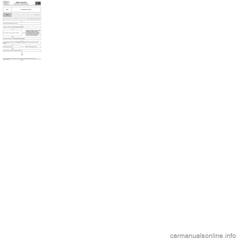
ALP2 The engine will not start
NOTESOnly consult this customer complaint after a complete check with the diagnostic tool.
Check that the fuel tank is correctly filled and that the fuel is correct: run TEST 13 Diesel fuel conformity check.
Check the levels of engine oil and coolant.
Check the air inlet circuit: run TEST 5 Air inlet circuit check.
Is the catalytic converter clogged or damaged?Replace the catalytic converter (see MR
364 (Mégane II), MR 370 (Scénic II),
MR 385 (Modus), MR 392 (Clio III), MR
411 (New Twingo), MR 417 (Kangoo 2),
Mechanical, 19B, Exhaust, Catalytic
converter: Removal - Refitting).
Check the electrical circuit: run TEST 2 Electrical circuit check.
Check the electrical conformity of the heater plugs (the resistance value of the heater plug must be less
than 2 Ω).
Is the timing set correctly? Carry out the necessary repairs.
Visually check the condition of the engine wiring harness.
YES
NO
NO
YES
A
DCM1.2_V48_ALP2/DCM1.2_V4C_ALP2/DCM1.2_V50_ALP2/DCM1.2_V54_ALP2/DCM1.2_V58_ALP2/DCM1.2_V5C_ALP2
Page 238 of 269
13B-238V6 MR-413-X44-13B000$210.mif
DIESEL INJECTION
Fault finding – Fault finding charts13B
DCM 1.2 Injection
Program No.: 4D
Vdiag No.: 48, 4C, 50,
54, 58, 5C
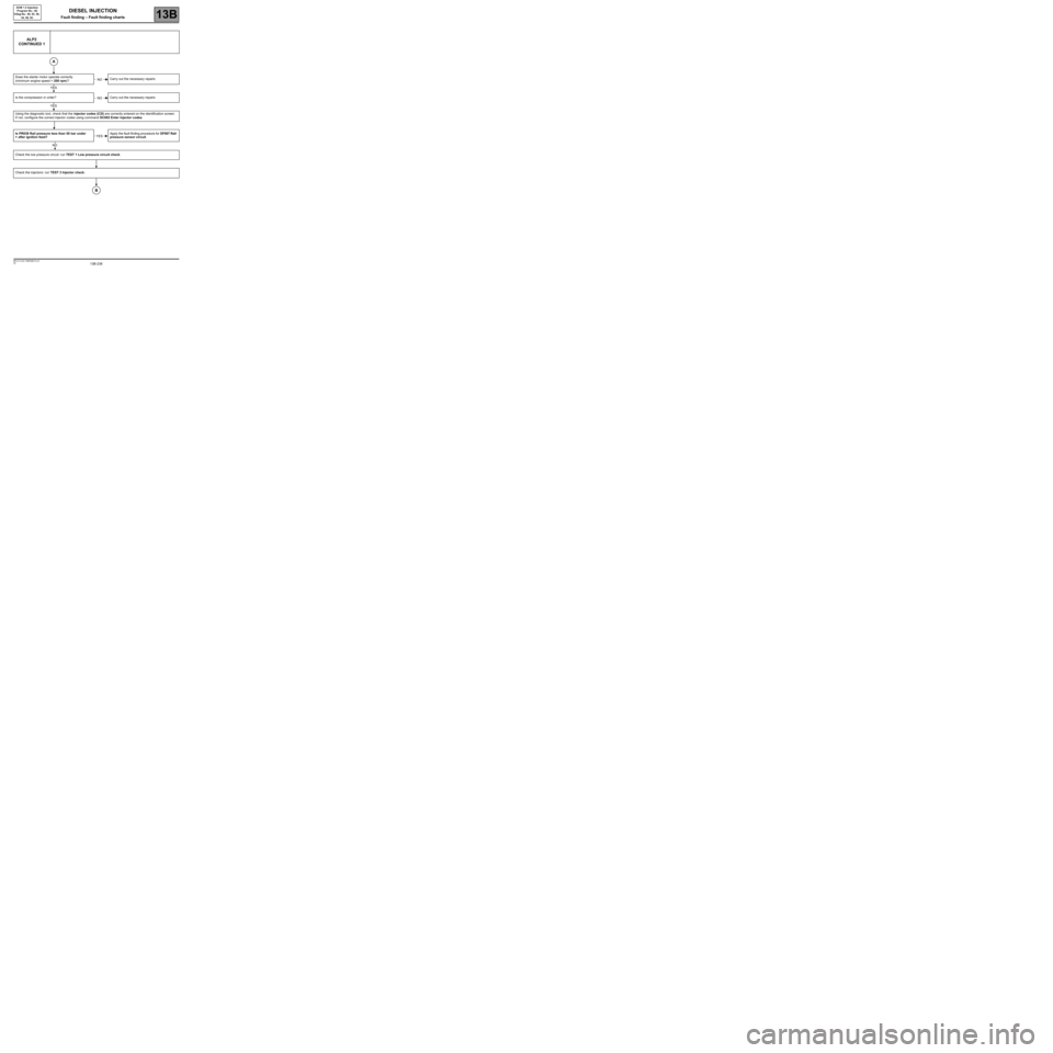
ALP2
CONTINUED 1
Does the starter motor operate correctly
(minimum engine speed = 200 rpm)?Carry out the necessary repairs
Is the compression in order? Carry out the necessary repairs
Using the diagnostic tool, check that the injector codes (C2I) are correctly entered on the identification screen.
If not, configure the correct injector codes using command SC002 Enter injector codes.
Is PR038 Rail pressure less than 50 bar under
+ after ignition feed?Apply the fault finding procedure for DF007 Rail
pressure sensor circuit.
Check the low pressure circuit: run TEST 1 Low pressure circuit check.
Check the injectors: run TEST 3 Injector check.
A
NO
YES
NO
YES
YES
NO
B