lights RENAULT TWINGO 2009 2.G Heating And Air Conditioning - Climate Control Workshop Manual
[x] Cancel search | Manufacturer: RENAULT, Model Year: 2009, Model line: TWINGO, Model: RENAULT TWINGO 2009 2.GPages: 99
Page 17 of 99
62B-17
MR-413-X44-62B000$230_eng.mif
V1
62B
CLIMATE CONTROL
Fault finding - Function
GENERAL INFORMATION:
The climate control function which is fitted to the new Twingo depends on the three computers: injection, UCH and
climate control (DISTRIBUTED FUNCTION).
Fault finding on the air conditioning is performed in two different ways using the diagnostic tool.
The first procedure consists of performing fault finding on each computer which allows dialogue to be established
with just one computer (select the climate control computer).
The second procedure consists of performing fault finding on each function which allows communication with all
three computers belonging to the CLIMATE CONTROL function.
DESCRIPTION OF THE OPERATION OF THE CLIMATE CONTROL COMPUTER:
The climate control computer controls the passenger compartment ventilation, the distribution motor, the mixing
motor and the recirculation motor.
The climate control computer also controls the interior temperature sensor.
The sensor and the three motors are connected to the climate control computer by wire connections. The climate
control computer controls the passenger compartment ventilation using a modulated control signal (square pulse
signal) sent to a power module (MVPE) by a wire connection.
All other signals used by the climate control computer or transmitted by this computer to other computers are sent on
the multiplex network.
The production of cold air (cold loop) and hot air (heating) is controlled by the other two computers involved in the
CLIMATE CONTROL function (UCH and engine injection computer).
Special notes on operation:
–When the engine is stopped, the passenger compartment fan rotates more slowly than when the engine is
running.
–If any of the actuators are faulty, the air conditioning can no longer control them, but the setting requests are still
displayed on the control panel: warning lights light up, display of symbols on the control panel (distribution motor
position, passenger compartment blower speed, AC symbol, etc.).
Vdiag No.: 44
MR-413-X44-62B000$230_eng.mif
Page 26 of 99
62B-26
MR-413-X44-62B000$414_eng.mif
V1
CLIMATE CONTROL
Fault finding - Interpretation of faults
Vdiag No.: 44
62B
DF007
PRESENT
OR
STOREDINTERIOR TEMPERATURE SENSOR CIRCUIT
CC.0 : Short circuit to earth
CO.1 : Short circuit or open circuit to + 12 V
NOTESConditions for running fault finding on a present or stored fault:
Apply this fault finding procedure if the fault reappears as present or stored after the
ignition is switched on and air conditioning activation is requested with the engine
running.
Special notes:
The interior temperature sensor is located at the top of the roof in the unit under the
rear view mirror.
Use the Wiring Diagram Technical Note for the New Twingo.
Check the connection and condition (possible wiring damage) of the connector of component 1872.
If the connector is faulty (see Technical Note 6015A, Repairing electrical wiring, Wiring: Precautions for the
repair), repair the connector, otherwise replace the wiring.
With connector A of component 419 and connector of union R301 disconnected, check the insulation and
continuity of the following connections between components R301 (dashboard/interior lights intermediate union)
and 419.
●connection 38JN
●connection 38GZ
If the connection or connections are faulty (see Technical Note 6015A, Repairing electrical wiring, Wiring:
Precautions for repair), repair the wiring, otherwise replace it.
With the connector of component 1872 disconnected, check the insulation and continuity of the following
connections between components R301 (dashboard/interior lights intermediate union) and 1872.
●connection 38JN
●connection 38GZ
If the connection or connections are faulty (see Technical Note 6015A, Repairing electrical wiring, Wiring:
Precautions for repair), repair the wiring, otherwise replace it.
Check the insulation of connections 38JN and 38GZ of component 1872.
If the connection or connections are faulty and there is a repair procedure (see Technical Note 6015A, Electrical
wiring repair, Wiring: Precautions for repair), repair the wiring, otherwise replace it.
Check the resistance of component 1872 between connections 38JN and 38GZ.
Replace the sensor if the resistance is not 10 kΩΩ Ω Ω
± 500 ΩΩ Ω Ω
at 25 ˚C. For more details, consult the electrical
specifications of the sensor according to the temperature (see Help).
If the fault is still present, contact the Techline.
AFTER REPAIRClear the stored faults.
Follow the instructions to confirm repair.
Deal with any other faults.
CLIM_V44_DF007
Page 36 of 99
62B-36
MR-413-X44-62B000$460_eng.mif
V1
Vdiag No.: 44CLIMATE CONTROL
Fault finding - Conformity check62B
MAIN SCREEN
NOTESOnly carry out this conformity check after a full check using the diagnostic tool
(fault reading and configuration checks).
Application conditions: engine stopped with ignition on (12 V APC), AIR
CONDITIONING OFF (air conditioning compressor not activated).
Note:
This page lists the statuses and parameters provided by the climate control computer
but which are not associated with the three sub-functions given in the conformity
check (PASSENGER COMPARTMENT VENTILATION, COLD LOOP and HEATING
sub-functions).
FunctionParameter or Status
checked or ActionDisplay and Notes Fault finding
Electrical suppliesPR092:Battery voltage10.5 V < X <14.4 VIn the event of a fault, see the
interpretation of this
parameter.
ET083:+ 12 V after
ignition present ABSENT: Ignition off.
PRESENT: Ignition on.In the event of a fault, refer to the
interpretation of this status.
ET002:+ 12 V side
lightsABSENT: Side lights off.
PRESENT: Side lights
on.In the event of a fault, refer to the
interpretation of this status.
PR122:Night lighting
level15 % = minimum
lighting level
99 % = maximum
lighting level
(side lights
off: 102 %)In the event of a fault, refer to the
interpretation of this status.
Note:
This parameter is displayed via
the climate control computer but
is generated by the instrument
panel.
Page 41 of 99
62B-41
MR-413-X44-62B000$460_eng.mif
V1
Vdiag No.: 44CLIMATE CONTROL
Fault finding - Conformity check62B
MAIN SCREEN
NOTESOnly carry out this conformity check after a full check using the diagnostic tool
(fault reading and configuration checks).
Application conditions: engine running, AIR CONDITIONING ON (air conditioning
compressor activated).
This page lists the statuses and parameters provided by the climate control computer
but which are not associated with the three sub-functions given in the conformity
check (PASSENGER COMPARTMENT VENTILATION, COLD LOOP and HEATING
sub-functions).
Order FunctionParameter or Status
checked or ActionDisplay and Notes Fault finding
1Electrical
suppliesPR092:Battery voltage10.5 V < X <14.4 VIn the event of a fault, see
the interpretation of this
parameter.
ET083:+ 12 V after
ignition present PRESENT:
Ignition on.In the event of a fault, refer
to the interpretation of this
status.
ET002:+ 12 V side
lightsABSENT: Side lights off.
PRESENT: Side lights
on.In the event of a fault, refer
to the interpretation of this
status.
PR122:Night lighting
levelBetween 15 % (minimum
lighting level) and 99 %
(maximum lighting level)
(side lights off: 102 %)In the event of a fault,
consult the interpretation
of this parameter
Note:
This parameter is displayed
by the climate control
computer but is generated
by the instrument panel.
Page 42 of 99
62B-42
MR-413-X44-62B000$506_eng.mif
V1
62B
CLIMATE CONTROL
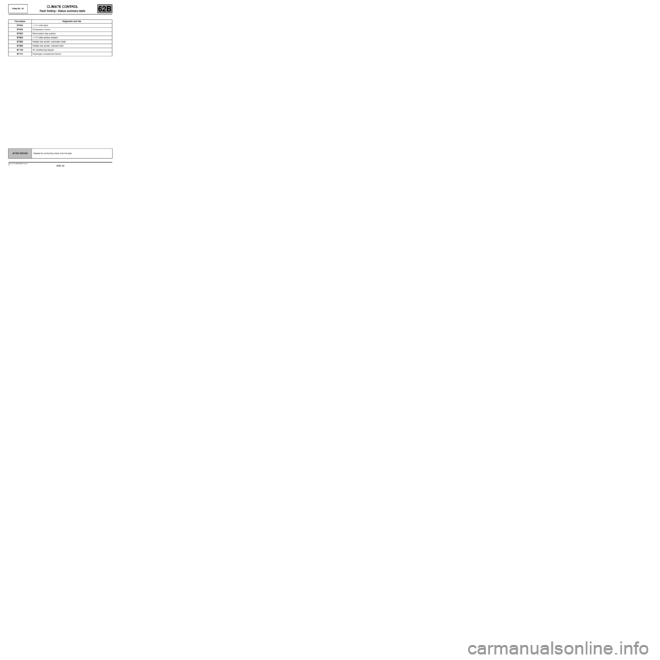
Fault finding - Status summary table
Tool status Diagnostic tool title
ET002+ 12 V side lights
ET020Compressor control
ET062Recirculation flap position
ET083+ 12 V after ignition present
ET085Heated rear screen: automatic mode
ET086Heated rear screen: manual mode
ET140Air conditioning request
ET141Passenger compartment blower
AFTER REPAIRRepeat the conformity check from the start.
Vdiag No.: 44
MR-413-X44-62B000$506_eng.mif
Page 43 of 99
62B-43
MR-413-X44-62B000$506_eng.mif
V1
CLIMATE CONTROL
Fault finding - Status summary table
Vdiag No.: 44
62B
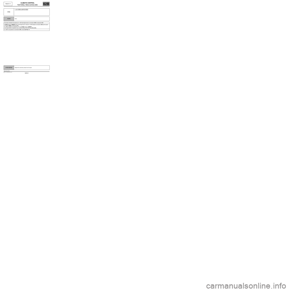
ET002
+ 12 V SIDE LIGHTS FEED
NOTESNone
This status indicates the presence of + 12 V side lights feed on connection LPD of component 419.
If ET002 displays ABSENT when the side light are lit, check for + 12 V between connection LPD and the earth
connection NAM of component 419.
If + 12 V is present on connection LPD and ET002 displays ABSENT.
If the status does not operate, carry out fault finding on the UCH (see 87B, UCH).
If + 12 V is not present on connection LPD, consult ALP No. 13.
AFTER REPAIRRepeat the conformity check from the start.
CLIM_V44_ET012
Page 93 of 99
62B-93
MR-413-X44-62B000$920_eng.mif
V1
Vdiag No.: 44CLIMATE CONTROL
Diagnostic - Fault finding chart62B
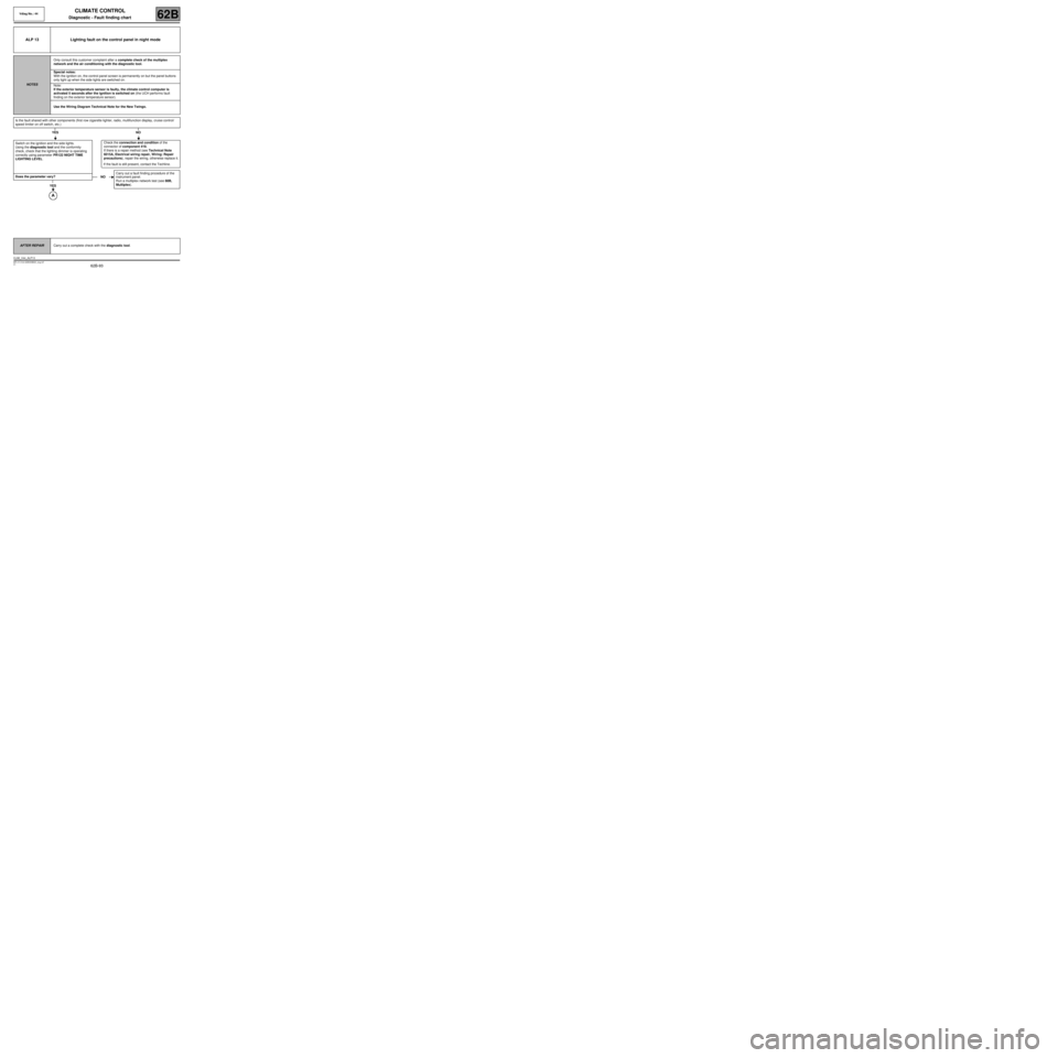
ALP 13 Lighting fault on the control panel in night mode
NOTESOnly consult this customer complaint after a complete check of the multiplex
network and the air conditioning with the diagnostic tool.
Special notes:
With the ignition on, the control panel screen is permanently on but the panel buttons
only light up when the side lights are switched on.
Note:
If the exterior temperature sensor is faulty, the climate control computer is
activated 5 seconds after the ignition is switched on (the UCH performs fault
finding on the exterior temperature sensor).
Use the Wiring Diagram Technical Note for the New Twingo.
Is the fault shared with other components (first row cigarette lighter, radio, multifunction display, cruise control/
speed limiter on off switch, etc.)
YES NO
Switch on the ignition and the side lights.
Using the diagnostic tool and the conformity
check, check that the lighting dimmer is operating
correctly using parameter PR122 NIGHT TIME
LIGHTING LEVEL.
Does the parameter vary?
YES
Check the connection and condition of the
connector of component 419.
If there is a repair method (see Technical Note
6015A, Electrical wiring repair, Wiring: Repair
precautions), repair the wiring, otherwise replace it.
If the fault is still present, contact the Techline.
NOCarry out a fault finding procedure of the
instrument panel.
Run a multiplex network test (see 88B,
Multiplex).
AFTER REPAIRCarry out a complete check with the diagnostic tool.
CLIM_V44_ALP13
Page 94 of 99
62B-94
MR-413-X44-62B000$920_eng.mif
V1
Vdiag No.: 44CLIMATE CONTROL
Diagnostic - Fault finding chart62B
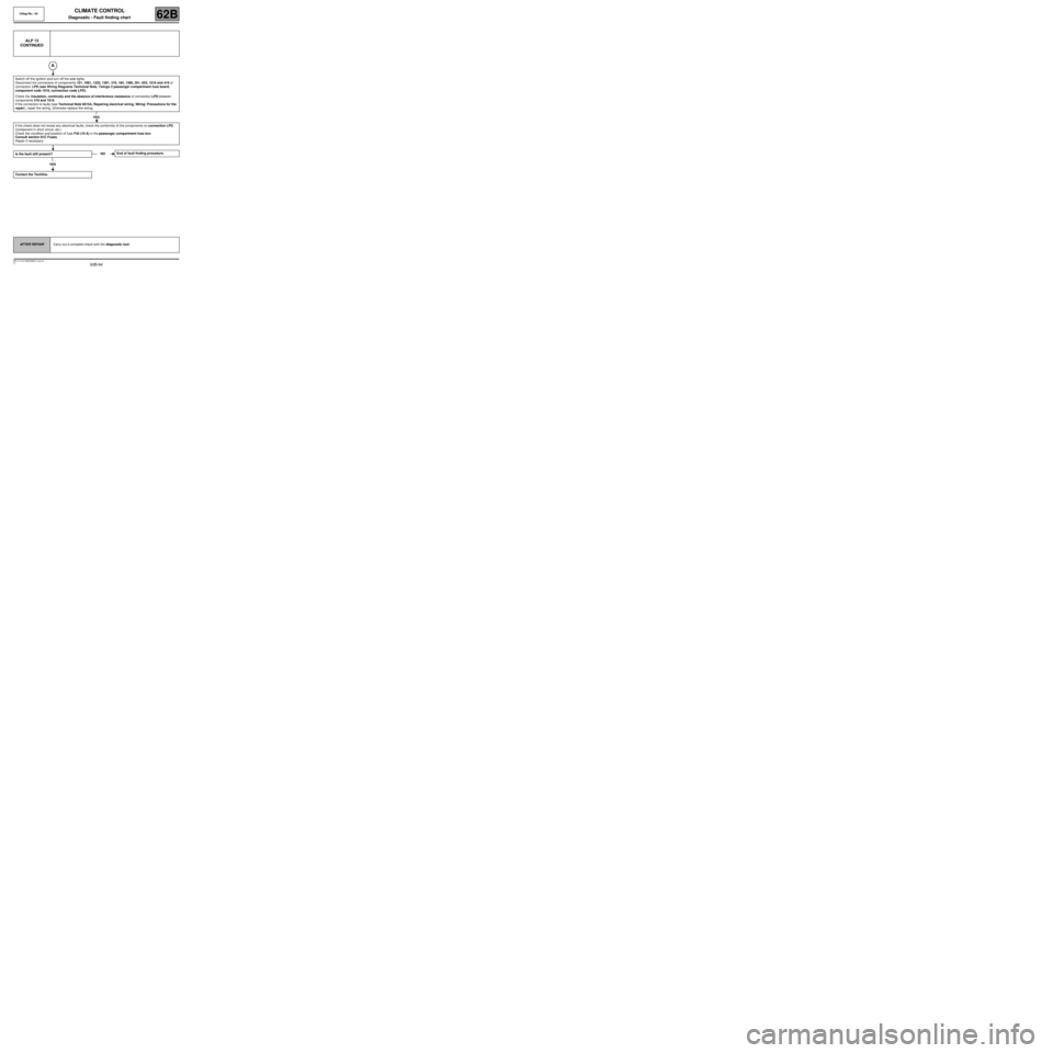
ALP 13
CONTINUED
Switch off the ignition and turn off the side lights.
Disconnect the connectors of components 101, 1081, 1222, 1391, 319, 184, 1390, 261, 653, 1016 and 419 of
connection LPD (see Wiring Diagrams Technical Note, Twingo 2 passenger compartment fuse board,
component code 1016, connection code LPD).
Check the insulation, continuity and the absence of interference resistance of connection LPD between
components 419 and 1016.
If the connection is faulty (see Technical Note 6015A, Repairing electrical wiring, Wiring: Precautions for the
repair), repair the wiring, otherwise replace the wiring.
YES
If the check does not reveal any electrical faults, check the conformity of the components on connection LPD
(component in short circuit, etc.)
Check the condition and position of fuse F42 (10 A) in the passenger compartment fuse box.
Consult section 81C Fuses.
Repair if necessary.
Is the fault still present?
YES
Contact the Techline.
NOEnd of fault finding procedure.
AFTER REPAIRCarry out a complete check with the diagnostic tool.