relay RENAULT TWINGO 2009 2.G Heating And Air Conditioning - Climate Control Workshop Manual
[x] Cancel search | Manufacturer: RENAULT, Model Year: 2009, Model line: TWINGO, Model: RENAULT TWINGO 2009 2.GPages: 99
Page 19 of 99
62B-19
MR-413-X44-62B000$230_eng.mif
V1
Vdiag No.: 44CLIMATE CONTROL
Fault finding - Function62B
Vehicle
multiplex
network
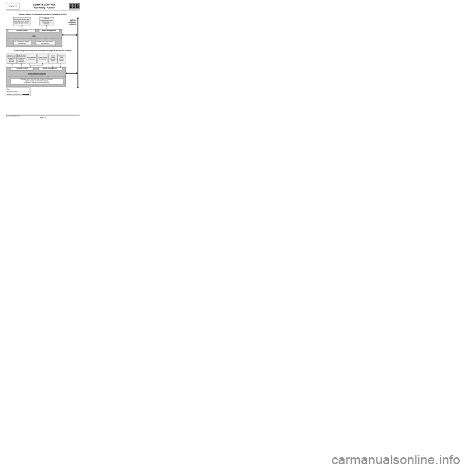
Summary diagram of components controlled or managed by the UCH:
Summary diagram of components controlled or managed by the injection computer Rear screen de-icing and
rear-view mirror de-icer
(depending on version)External
temperature sensor
(depending on
version)
Actuator control Sensor management
UCH
Air conditioning request
managementHeated rear screen control
management
Relay No. 1 for
the Passenger
Compartment
Heating
ResistorsRelay No. 2 for
the Passenger
Compartment
Heating
ResistorsAir conditioning
compressorEngine cooling
fan assemblyEngine
coolant
temperature
sensorRefrigerant
fluid
pressure
sensor
Actuator control Sensor management
Engine injection computer
Management of the cold loop (refrigerant pressure,
engine cooling fan activation request,
compressor activation authorisation, etc.)
Key:
Wire connections =
Multiplex connections =
Page 82 of 99

62B-82
MR-413-X44-62B000$874_eng.mif
V1
Vdiag No.: 44CLIMATE CONTROL
Diagnostic - Fault finding chart62B
ALP 8
CONTINUED 3
Carry out fault finding on the injection system to ensure that no fault is present (if faults are displayed by the injection
computer, engagement of the air conditioning may be inhibited). If there are present or stored faults, carry out the necessary
repairs (see 13B, Diesel injection or 17B, Petrol injection).
Check that the refrigerant fluid pressure is correct (neither too low nor too high) using the PR037 Refrigerant fluid
pressure parameter (see Conformity check, Cold loop sub-function).
Check that the engine cooling fan assembly is at speed 1 by
viewing the following status on the cold loop sub-function
screen:
- Status ET022 Low-speed fan assembly request should
display ACTIVE.
Note:
These statuses are not displayed by all types of injection
(see Conformity check, Cold loop sub-function).
Does the engine cooling fan operate at low speed?
YES
NO
Using the diagnostic tool, run command
AC154 Low speed fan assembly relay.
Does the engine cooling fan operate at
low speed?
NO YES
Connector of component 321 disconnected. Connect a test
light between connection 49L of component 321 and the
chassis earth and run command AC154 Low speed fan
assembly relay.
Does the test light illuminate?
YES NO
Carry out fault finding
on the injection
system (sub-function:
cold loop and engine
cooling for low speed
fan assembly
activation).
Measure the resistance of component 321, between connections
49L and 49B of component 321. If the resistance measured is
infinite, replace the fan assembly resistor (component 321).D
AFTER REPAIRCarry out a complete check with the diagnostic tool.
Page 83 of 99
62B-83
MR-413-X44-62B000$874_eng.mif
V1
CLIMATE CONTROL
Diagnostic - Fault finding chart
Vdiag No.: 44
62B
ALP 8
CONTINUED 4
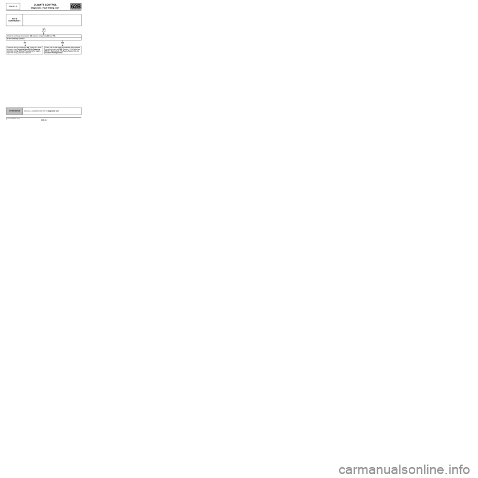
Check the continuity of connection 49L between components 321 and 700.
Is the continuity correct?
NO YES
Continuity fault on connection 49L. If there is a repair
procedure (see Technical Note 6015A, Repairing
electrical wiring, Wiring: Precautions for repair),
repair the wiring, otherwise replace it.Check that the low speed fan assembly relay operates
correctly (component 700). Replace it if it is faulty (see
MR 411 Mechanical, 81C, Fuses, Fuses: List and
location of components).
D
AFTER REPAIRCarry out a complete check with the diagnostic tool.
Page 84 of 99
62B-84
MR-413-X44-62B000$874_eng.mif
V1
Vdiag No.: 44CLIMATE CONTROL
Diagnostic - Fault finding chart62B
ALP 8
CONTINUED 5
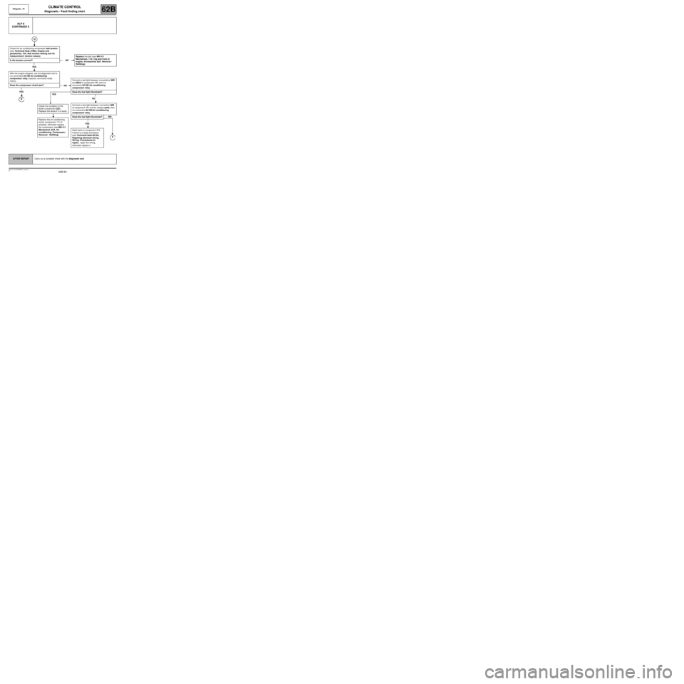
Check the air conditioning compressor belt tension
(see Technical Note 3786A, Engine and
peripherals, 10A, Belt tension setting tool Hz
measurement: tension values).
Is the tension correct?
YES
With the engine stopped, use the diagnostic tool to
run command AC180 Air conditioning
compressor relay (injection command mode
menu).
Does the compressor clutch jam?
YES
E
NOReplace the belt (see MR 411
Mechanical, 11A, Top and front of
engine, Accessories belt: Removal -
Refitting).
NOConnect a test light between connections 38R
and MAS of component 171 and run
command AC180 Air conditioning
compressor relay.
Does the test light illuminate?
NO
Connect a test light between connection 38R
of component 171 and the chassis earth, then
run command AC180 Air conditioning
compressor relay.
Does the test light illuminate?
YES
Earth fault on component 171.
If there is a repair procedure
(see Technical Note 6015A,
Repairing electrical wiring,
Wiring: Precautions for
repair), repair the wiring,
otherwise replace it.
NO
F
YES
Check the condition of the
diode (component 322).
Replace the diode if it is faulty.
Replace the air conditioning
clutch (component 171) if
possible, otherwise replace
the compressor (see MR 411
Mechanical, 62A, Air
conditioning, Compressor:
Removal - Refitting).
AFTER REPAIRCarry out a complete check with the diagnostic tool.
Page 85 of 99
62B-85
MR-413-X44-62B000$874_eng.mif
V1
CLIMATE CONTROL
Diagnostic - Fault finding chart
Vdiag No.: 44
62B
ALP 8
CONTINUED 6
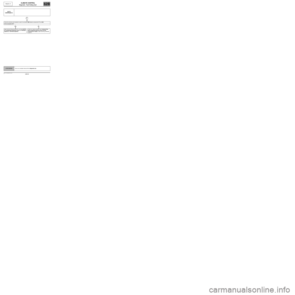
Check the continuity and insulation to earth of connection 38R between components 171 and 584.
Is the connection OK?
YES NO
Apply the fault finding procedure for command AC180
Air conditioning compressor relay (see 13B Diesel
injection or 17B Petrol injection).If there is a repair procedure (see Technical Note
6015A, Repairing electrical wiring, Wiring:
Precautions for repair), repair the wiring, otherwise
replace it.
F
AFTER REPAIRCarry out a complete check with the diagnostic tool.
Page 87 of 99
62B-87
MR-413-X44-62B000$874_eng.mif
V1
Vdiag No.: 44CLIMATE CONTROL
Diagnostic - Fault finding chart62B
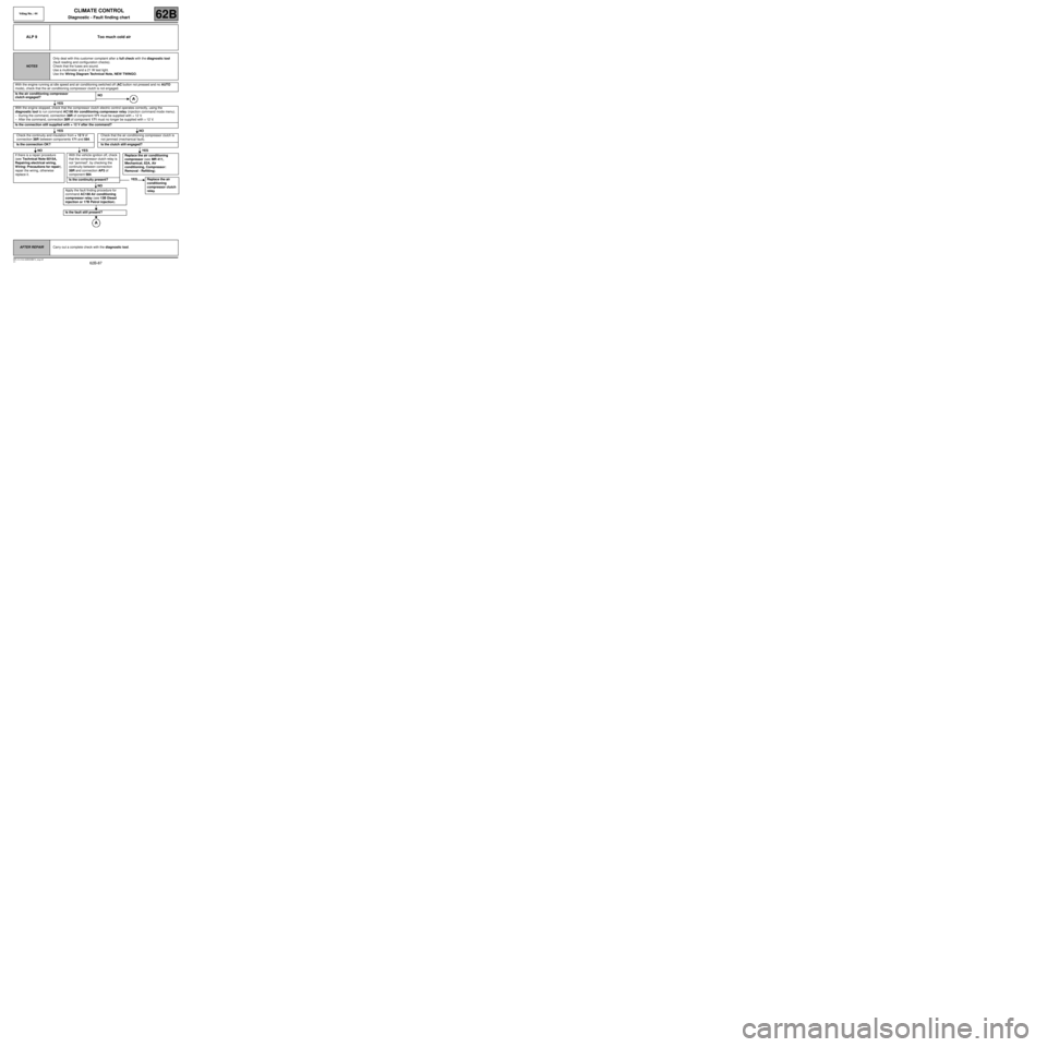
ALP 9 Too much cold air
NOTESOnly deal with this customer complaint after a full check with the diagnostic tool
(fault reading and configuration checks).
Check that the fuses are sound.
Use a multimeter and a 21 W test light.
Use the Wiring Diagram Technical Note, NEW TWINGO.
With the engine running at idle speed and air conditioning switched off (AC button not pressed and no AUTO
mode), check that the air conditioning compressor clutch is not engaged.
Is the air conditioning compressor
clutch engaged?NO
YES
With the engine stopped, check that the compressor clutch electric control operates correctly, using the
diagnostic tool to run command AC180 Air conditioning compressor relay (injection command mode menu).
–During the command, connection 38R of component 171 must be supplied with + 12 V.
–After the command, connection 38R of component 171 must no longer be supplied with + 12 V.
Is the connection still supplied with + 12 V after the command?
YES NO
Check the continuity and insulation from + 12 V of
connection 38R between components 171 and 584.Check that the air conditioning compressor clutch is
not jammed (mechanical fault).
Is the connection OK? Is the clutch still engaged?
NO YES YES
If there is a repair procedure
(see Technical Note 6015A,
Repairing electrical wiring,
Wiring: Precautions for repair),
repair the wiring, otherwise
replace it.With the vehicle ignition off, check
that the compressor clutch relay is
not “jammed”, by checking the
continuity between connection
38R and connection AP3 of
component 584.
Is the continuity present?
NO
Apply the fault finding procedure for
command AC180 Air conditioning
compressor relay (see 13B Diesel
injection or 17B Petrol injection).
Is the fault still present?
Replace the air conditioning
compressor (see MR 411,
Mechanical, 62A, Air
conditioning, Compressor:
Removal - Refitting).
YES Replace the air
conditioning
compressor clutch
relay.
AFTER REPAIRCarry out a complete check with the diagnostic tool.