battery RENAULT TWINGO 2009 2.G Heating And Air Conditioning - Heating Workshop Manual
[x] Cancel search | Manufacturer: RENAULT, Model Year: 2009, Model line: TWINGO, Model: RENAULT TWINGO 2009 2.GPages: 29
Page 4 of 29
61A-4
MR-413-X44-61A000$125_eng.mif
V1
HEATING
Fault finding - Introduction61A
Visual inspection of the sealing:
(Only for watertight connectors)
●Check for the seal on the connection (between the 2 parts of the connection).
●Check the seal at the back of the connectors:
–For unit joints (1 for each wire), check that the unit joints are present on each electrical wire and that they
are correctly positioned in the opening (level with the housing). Check that plugs are present on openings
which are not used.
–For a grommet seal (one seal which covers the entire internal surface of the connector), check that the
seal is present.
–For gel seals, check for gel in all of the openings without removing the excess or any protruding sections
(it does not matter if there is gel on the contacts).
–For hotmelt sealing (heat-shrink sheath with glue), check that the sheath has contracted correctly on the
rear of the connectors and electrical wires, and that the hardened glue comes out of the side of the wire.
●Check that there is no damage to any of the seals (cuts, burns, significant deformation, etc.).
If a fault is detected, repair or replace the wiring (see Technical Note 6015A, Repairing electrical wiring, Wiring:
Precautions for repair).
5. FAULT FINDING LOG
You will always be asked for this log:
●when requesting technical assistance from Techline,
●for approval requests when replacing parts for which approval is mandatory,
●to be attached to monitored parts for which reimbursement is requested. The log is needed for warranty
reimbursement, and enables better analysis of the parts removed.
6. SAFETY INSTRUCTIONS
Safety rules must be observed during any work on a component to prevent any damage or injury:
–check the battery voltage to avoid incorrect operation of computer functions,
–do not smoke,
–use the proper tools. IMPORTANTIMPORTANT
Any fault on a complex system requires thorough fault finding with the appropriate tools. The
FAULT FINDING LOG, which should be completed during the procedure, enables you to keep
track of the procedure which is carried out. It is an essential document when consulting the
manufacturer.
IT IS THEREFORE MANDATORY TO FILL OUT A FAULT FINDING LOG EACH TIME FAULT FINDING IS
CARRIED OUT
Page 11 of 29
61A-11
MR-413-X44-61A000$625_eng.mif
V1
61A
HEATING
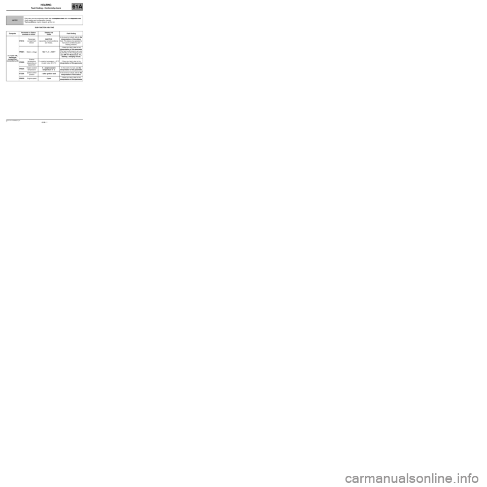
Fault finding - Conformity check
SUB-FUNCTION: HEATING
NOTESOnly carry out this conformity check after a complete check with the diagnostic tool
(fault reading and configuration checks).
Test conditions: engine stopped, ignition on.
ComputerParameter or Status
checked or ActionDisplay and
notesFault finding
UCH (see 87B,
Passenger
compartment
connection unit)ET015:Passenger
compartment
blowerINACTIVE
(according to test conditions:
see Notes).In the event of a fault, refer to the
interpretation of this status.
Note: This status only operates for
manual air conditioning and
heating versions.
PR001: Battery voltage10.5 V < X < 14.4 VIf there is a fault, refer to the
interpretation of this parameter
If the fault is still present, carry out
fault finding on the charging circuit
(see MR 411 Mechanical, 16A,
Starting - charging circuit).
PR002: Exterior
temperature
(depending on
equipment)X = exterior temperature ± 5 °C
(invalid value: 215 °C)If there is a fault, refer to the
interpretation of this parameter
PR024: Engine coolant
temperatureX = engine coolant
temperature in ˚CIn the event of a fault, see the
interpretation of this parameter.
ET239: Ignition switch
position+ after ignition feedIn the event of a fault, refer to the
interpretation of this status.
PR025: Engine speed0 rpmIf there is a fault, refer to the
interpretation of this parameter
MR-413-X44-61A000$625_eng.mif
Page 14 of 29
61A-14
MR-413-X44-61A000$625_eng.mif
V1
HEATING
Fault finding - Conformity check61A
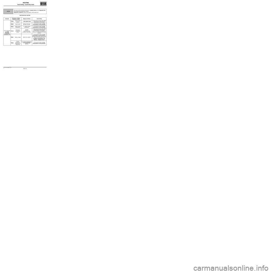
SUB-FUNCTION: HEATING
NOTESOnly carry out this conformity check after a complete check with the diagnostic tool
(fault reading and configuration checks).
Application conditions: engine at idle speed, vehicle speed zero.
ComputerParameter or Status
checked or ActionDisplay and Notes Fault finding
UCH (continued)
(see 87B,
Passenger
compartment
connection unit)ET239: Ignition switch
position+ after ignition feedIn the event of a fault, refer to the
interpretation of this status.
PR025: Engine speed800 rpm ± 50 rpmIn the event of a fault, see the
interpretation of this parameter.
PR024: Engine coolant
temperatureX = engine coolant
temperatureIn the event of a fault, see the
interpretation of this parameter.
ET015: Passenger
compartment
blowerACTIVE
(according to test
conditions: see Notes).In the event of a fault, refer to the
interpretation of this status.
Note: This status only operates for
manual air conditioning and heating
versions.
PR001: Battery voltage12.5 V < X < 14.4 VIn the event of a fault, see the
interpretation of this parameter. If
the fault is still present, carry out fault
finding on the charging circuit
(see MR 411 Mechanical, 16A,
Starting - charging circuit).
PR002: Exterior
temperature
(depending on
equipment)X = exterior temperature:
5 ˚C (invalid value:
215 ˚C)In the event of a fault, see the
interpretation of this parameter.
Page 21 of 29
61A-21
MR-413-X44-61A000$875_eng.mif
V1
HEATING
Fault finding - Fault finding charts61A
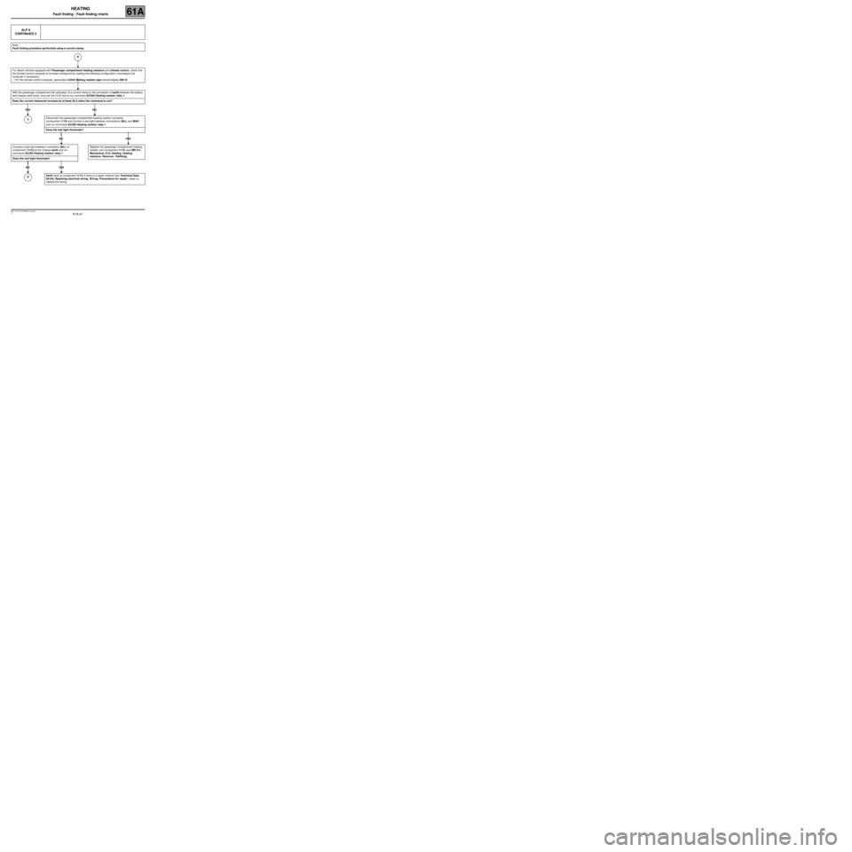
ALP 6
CONTINUED 2
Note:
Fault finding procedure performed using a current clamp.
For diesel vehicles equipped with Passenger compartment heating resistors and climate control, check that
the climate control computer is correctly configured by reading the following configuration (reconfigure the
computer if necessary):
–For the climate control computer, parameter LC044 Heating resistor type should display 900 W.
With the passenger compartment fan activated, fit a current clamp to the connection of earth between the battery
and chassis earth point, and use the CLIP tool to run command AC250 Heating resistor relay 1.
Does the current measured increase by at least 20 A when the command is run?
YES NO
Connect a test light between connection 38LL of
component 1113 and the chassis earth and run
command AC250 Heating resistor relay 1.
Does the test light illuminate?
NO YES
Disconnect the passenger compartment heating resistor connector
(component 1113) and connect a test light between connections 38LL and MAK
and run command AC250 Heating resistor relay 1.
Does the test light illuminate?
NO YES
Replace the passenger compartment heating
resistor unit (component 1113) (see MR 411,
Mechanical, 61A, Heating, Heating
resistors: Removal - Refitting).
Earth fault on component 1113. If there is a repair method (see Technical Note
6015A, Repairing electrical wiring, W iring: Precautions for repair), repair or
replace the wiring.
B
C
D
Page 22 of 29
61A-22
MR-413-X44-61A000$875_eng.mif
V1
HEATING
Fault finding - Fault finding charts61A
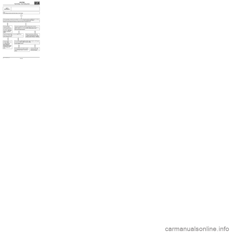
ALP 6
CONTINUED 3
Note:
Fault finding procedure performed using a current clamp.
With the passenger compartment fan activated, fit a current clamp to the connection of earth between the battery
and chassis earth point, and use the CLIP tool to run command AC251 Heating resistor relay 2.
Does the current measured increase by at least 40 A when the command is run?
YES NO
With the passenger
compartment heating
resistors operating, carry
out a conformity check on
the injection, heating sub-
function (see 13B, Diesel
injection, Conformity
check).
Disconnect the passenger compartment heating resistor connector
(component 1113) and connect a test light between each of the connections
38LM and MAK and run command AC251 Heating resistor relay 2.
Does the test light illuminate?
NO YES
Replace the passenger compartment
heating resistor unit (component 1113)
(see MR 411, Mechanical, 61A, Heating,
Heating resistors: Removal - Refitting).Check the continuity of the 2 connections 38LM between
components 1113 and 1068.
Is the continuity correct?
NO YES
Continuity fault on
connection 38LM. If there
is a repair method
(see Technical Note
6015A, Repairing
electrical wiring, Wiring:
Precautions for repair),
repair or replace the
wiring.Re-run command AC251 Heating resistor relay 2. Check for + 12 V supply
on connections 3FB and BP9 of component 1068.
Are the supplies correct?
YES NO
Check the engine fuse
and relay box (see 16A,
Starting Charging).Run fault finding on the injection computer
for the heating element resistor 2 command
(see 13B, Diesel injection, Conformity
check).
C