heater RENAULT TWINGO 2009 2.G Heating And Air Conditioning - Manual Air Conditioning Workshop Manual
[x] Cancel search | Manufacturer: RENAULT, Model Year: 2009, Model line: TWINGO, Model: RENAULT TWINGO 2009 2.GPages: 63
Page 7 of 63
62C-7
MR-413-X44-62C000$182_eng.mif
V1
62C
MANUAL AIR CONDITIONING
Fault finding - List and location of components
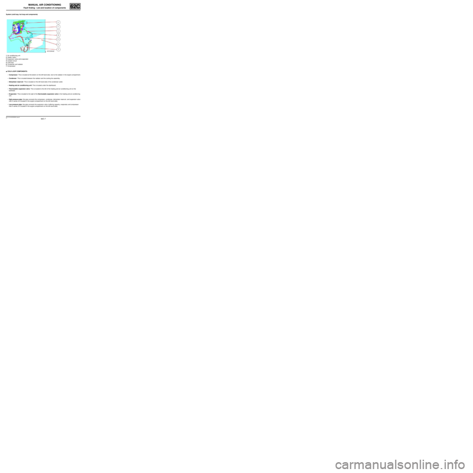
System (cold loop, hot loop and components)
1Air conditioning unit
2Heater matrix
3Expansion valve and evaporator
4Coolant circuit
5Cold loop
6Condenser and radiator
7Compressor
●COLD LOOP COMPONENTS:
–Compressor: This is located at the bottom on the left-hand side, next to the radiator in the engine compartment.
–Condenser: This is located between the radiator and the cooling fan assembly.
–Dehydrator reservoir: This is located on the left-hand side of the condenser outlet.
–Heating and air conditioning unit: This is located under the dashboard.
–Thermostatic expansion valve: This is located to the left of the heating and air conditioning unit on the
bulkhead.
–Evaporator: This is located to the right of the thermostatic expansion valve in the heating and air conditioning
unit.
–High pressure pipe: this pipe connects the compressor, condenser, dehydrator reservoir, and expansion valve
inlet in series (it is located in the engine compartment on the left-hand side).
–Low pressure pipe: this pipe connects the expansion valve, buffering capacity, evaporator, and compressor
inlet in series (it is located in the engine compartment on the left-hand side).
MR-413-X44-62C000$182_eng.mif
Page 8 of 63
62C-8
MR-413-X44-62C000$182_eng.mif
V1
MANUAL AIR CONDITIONING
Fault finding - List and location of components62C
●HEATING COMPONENTS
–Heater matrix: This is located at the bottom of the heating and air conditioning unit.
–Heating resistors: These are located at the bottom of the heater matrix on the driver's side (depending on the
equipment).
●ACTUATORS:
–Air distribution flap: This is located in the heating and air conditioning unit.
–Air mixing flap: This is located in the heating and air conditioning unit.
–Recirculation flap: This is located behind the dashboard.
–Flap motors: These are located close to the flaps (climate control).
●OTHERS
–Passenger compartment blower unit: This is located in the heating and air conditioning unit.
–Cooling fan assembly: This is located in the front panel of the vehicle, in front of the condenser.
–Air pipes: These are located under the dashboard.
Page 9 of 63
62C-9
MR-413-X44-62C000$273_eng.mif
V1
62C
MANUAL AIR CONDITIONING
Fault finding - Role of components
COLD LOOP COMPONENTS
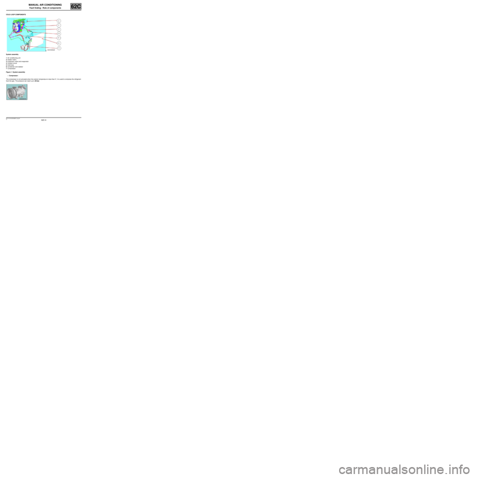
System assembly
1Air conditioning unit
2Heater matrix
3Expansion valve and evaporator
4Coolant circuit
5Cold loop
6Condenser and radiator
7Compressor
Figure 1: System assembly
–Compressor:
The compressor is not activated when the exterior temperature is less than 0˚; it is used to compress the refrigerant
fluid into gas. The pressure can reach up to 28 bar.
MR-413-X44-62C000$273_eng.mif
Page 11 of 63
62C-11
MR-413-X44-62C000$273_eng.mif
V1
MANUAL AIR CONDITIONING
Fault finding - Role of components62C
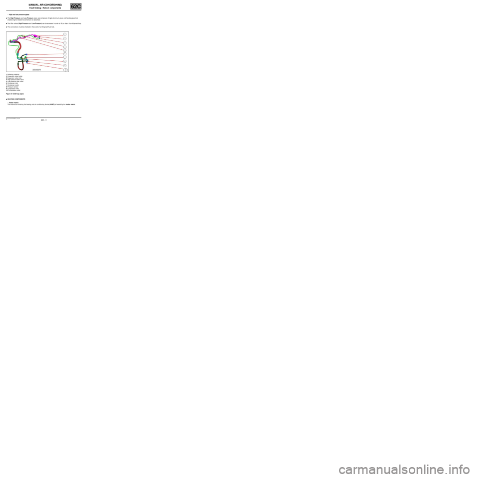
–High and low pressure pipes:
●The High Pressure and Low Pressure pipes are composed of rigid aluminium pipes and flexible pipes that
enable engine-related movements to be absorbed.
●Two filler valves (High Pressure and Low Pressure) can be accessed in order to fill (or drain) the refrigerant loop.
●The connections must be checked in the event of a refrigerant fluid leak.
1Buffering capacity
2Expansion valve outlet
3Expansion valve inlet
4High pressure filler valve
5Low pressure filler valve
6Condenser inlet
7Condenser outlet
8Pressure sensor
9Compressor inlet
10 Compressor outlet
Figure 6: Cold loop pipes
●HEATING COMPONENTS
–Heater matrix:
The external air entering the heating and air conditioning device (HVAC) is heated by the heater matrix.
Page 16 of 63
62C-16
MR-413-X44-62C000$455_eng.mif
V1
MANUAL AIR CONDITIONING
Fault finding - Function62C
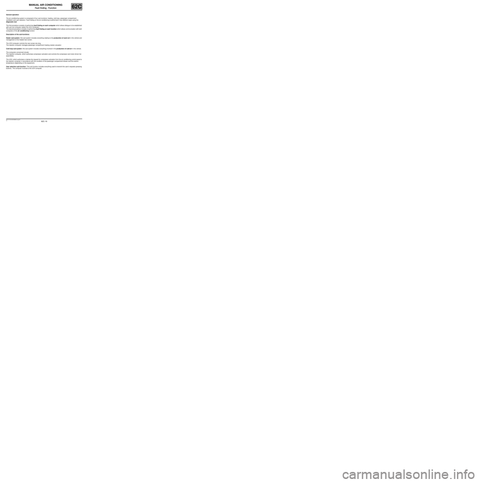
General operation
The air conditioning system is composed of four sub-functions: heating, cold loop, passenger compartment
ventilation and user selection. Fault finding on the air conditioning is performed in two different ways using the
diagnostic tool.
The first procedure consists of performing fault finding on each computer which allows dialogue to be established
with just one computer (select the UCH computer).
The second procedure consists of performing fault finding on each function which allows communication with both
computers of the air conditioning function.
Description of the sub-functions:
Heater sub-system: this sub-system includes everything relating to the production of warm air in the vehicle and
management of the heated rear screen.
The UCH computer controls the rear screen de-icing.
The injection computer manages passenger compartment heating resistor actuation
Cold loop sub-system: this sub-system includes everything involved in the production of cold air in the vehicle.
The computers concerned include:
The injection computer, which authorises compressor activation and controls the compressor and motor-driven fan
assemblies.
The UCH, which authorises or denies the request for compressor activation from the air conditioning control panel to
the injection computer in accordance with the condition of the passenger compartment blower and the exterior
temperature (depending on the equipment).
User selection sub-function: This sub-function includes everything used to transmit the user's requests (pressing
buttons). The computer involved is the UCH computer.
Page 41 of 63
62C-41
MR-413-X44-62C000$819_eng.mif
V1
MANUAL AIR CONDITIONING
Fault finding - Fault finding charts62C
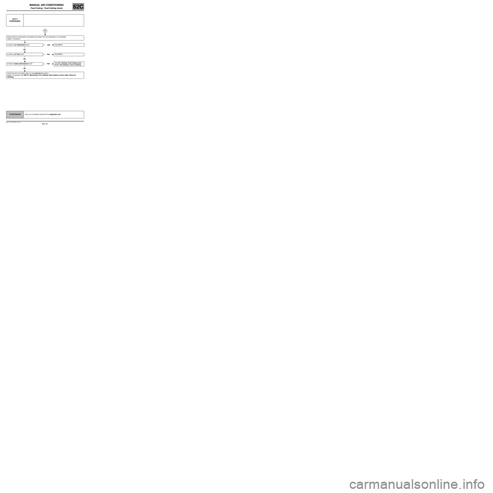
ALP 4
CONTINUED
Check that the condensation evacuation port (water from the evaporator) is not blocked.
Repair if necessary.
Is there an air distribution fault?
NO
Is there an air flow fault?
NO
Is there a heater performance fault?
NO
Check that the recirculation flap is in the external air position.
Repair if necessary (see MR 411 Mechanical, 61A, Heating, Recirculation control cable: Removal -
Refitting).
YESSee ALP 2.
YESSee ALP 3.
YESSee 61A, Heating, Fault finding chart,
ALP 6: No heating or loss of heating.
AFTER REPAIRCarry out a complete check with the diagnostic tool.
Page 60 of 63
62C-60
MR-413-X44-62C000$910_eng.mif
V1
MANUAL AIR CONDITIONING
Fault finding - Fault finding charts62C
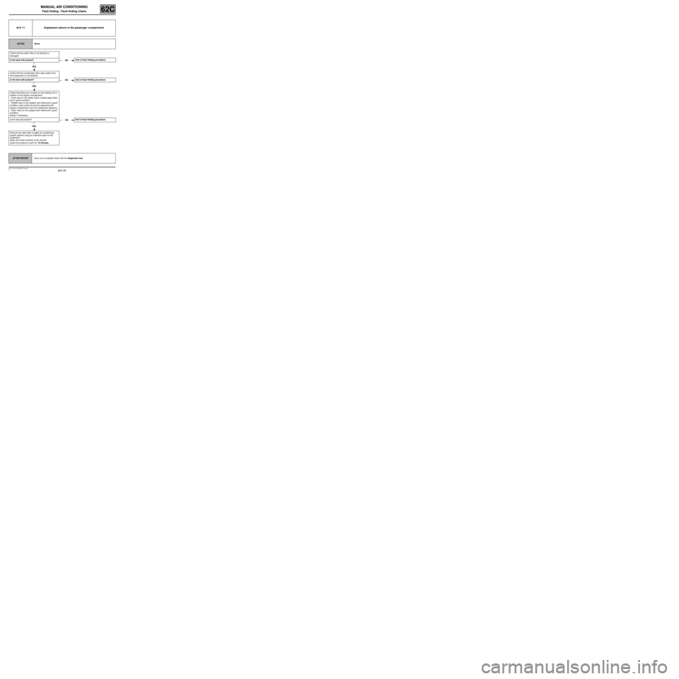
ALP 11 Unpleasant odours in the passenger compartment
NOTESNone.
Check that the cabin filter is not blocked or
damaged.
Is the fault still present?
YES
Check that the condensate drain pipe (water from
the evaporator) is not blocked.
Is the fault still present?
YES
Check that there are no leaks on the heating unit in
relation to the engine compartment:
- Foam seal on the heater matrix coolant pipes fitted
and in good condition.
- Rubber seal on the radiator tank fitted and in good
condition (seal under the bonnet separating the
engine compartment from the windscreen aperture).
- Drain valve on the radiator tank fitted and in good
condition.
Repair if necessary.
Is the fault still present?
YES
Remove the cabin filter to apply air conditioning
system cleaner using an extension pipe on the
evaporator.
Spray the entire contents of the aerosol.
Leave the product to work for 15 minutes.
NOEnd of fault finding procedure.
NOEnd of fault finding procedure.
NOEnd of fault finding procedure.
AFTER REPAIRCarry out a complete check with the diagnostic tool.