lights RENAULT TWINGO 2009 2.G Mechanism And Accessories Workshop Manual
[x] Cancel search | Manufacturer: RENAULT, Model Year: 2009, Model line: TWINGO, Model: RENAULT TWINGO 2009 2.GPages: 95
Page 20 of 95
52A-6
NON-SIDE OPENING ELEMENT MECHANISMS
Sunroof operating mechanism: Removal - Refitting
52A
REMOVAL
I - REMOVAL PREPARATION OPERATION
aPartially open the sunroof mobile panel.
aLock the airbag computer using the Diagnostic tool
(see Fault finding - Replacement of components)
(MR 413, 88C, Airbags and seat belt pretensioners).
aDisconnect the battery (see Battery: Removal - Re-
fitting) (MR 411, 80A, Battery).
aRemove:
-the sunroof console (see Sunroof switch: Remo-
val - Refitting) (MR 411, 87D, Electric window win-
ders - Sunroof),
-the sun visors (see 57A, Interior equipment, Sun
visor: Removal - Refitting, page 57A-16) ,
-the A-pillar trims (see Windscreen pillar trim: Re-
moval - Refitting) (MR 412, 71A, Body internal
trim),
-the rear bench seatback (depending on equipment
level) (see Rear bench seatback: Removal - Re-
fitting) (MR 412, 76A, Rear seat frames and run-
ners),
-the rear parcel shelf side trim panels (see Rear
parcel shelf side trim: Removal - Refitting) (MR
412, 71A, Body internal trim),-the rear panel trims (see Rear panel lining: Re-
moval - Refitting) (MR 412, 71A, Body internal
trim),
-the B-pillar upper trims (see B-pillar upper trim:
Removal - Refitting) (MR 412, 71A, Body internal
trim),
-the rear quarter panel trims (see Quarter panel
trim: Removal - Refitting) (MR 412, 71A, Body in-
ternal trim),
-the headlining (see Headlining: Removal - Refit-
ting) (MR 412, 71A, Body internal trim),
-the cross member mounting of the sunroof sun vi-
sor (see 52A, Non-side opening element mecha-
nisms, Sunroof sun visors: Removal - Refitting,
page 52A-15) ,
-the roof protection strips (see 55A, Exterior pro-
tection, Roof protection strip: Removal - Refit-
ting, page 55A-17) .
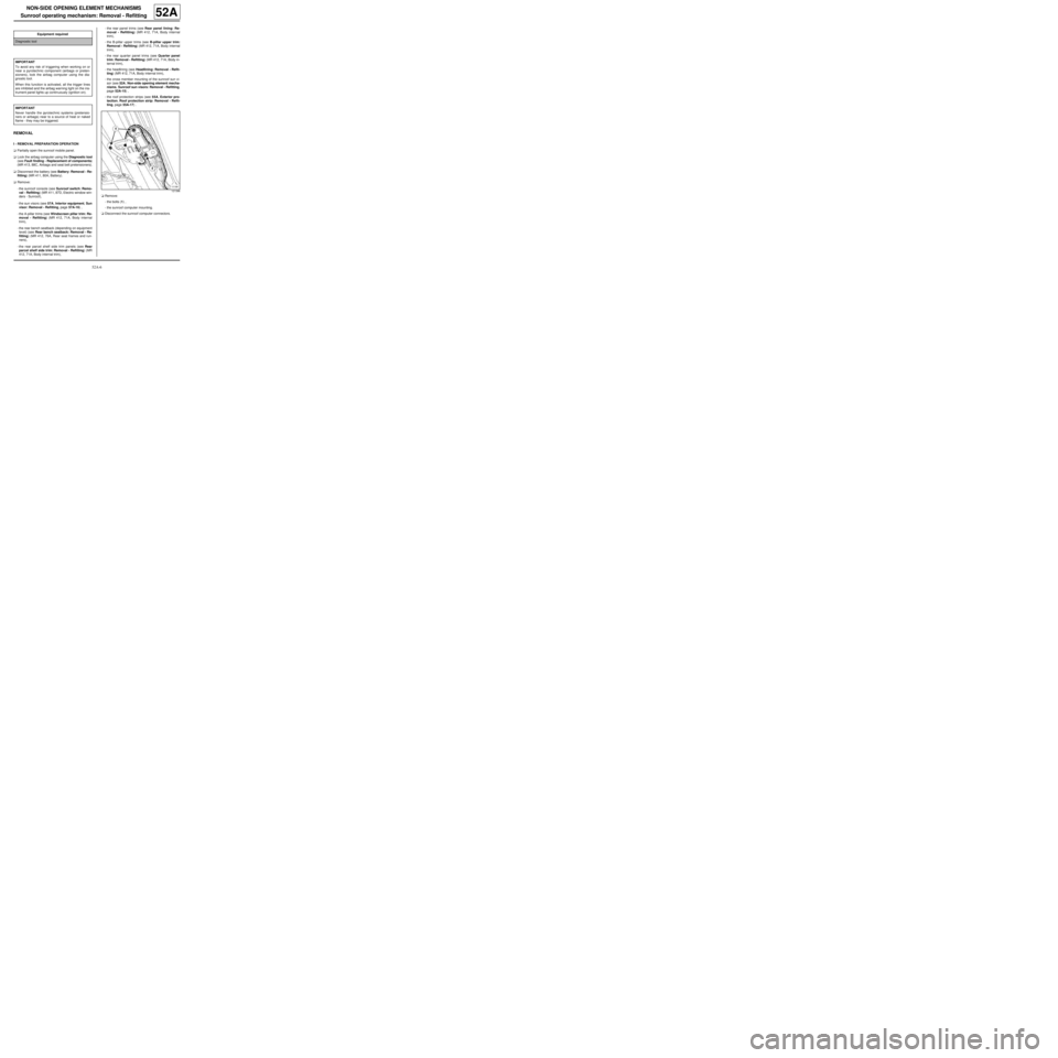
aRemove:
-the bolts (1) ,
-the sunroof computer mounting.
aDisconnect the sunroof computer connectors. Equipment required
Diagnostic tool
IMPORTANT
To avoid any risk of triggering when working on or
near a pyrotechnic component (airbags or preten-
sioners), lock the airbag computer using the dia-
gnostic tool.
When this function is activated, all the trigger lines
are inhibited and the airbag warning light on the ins-
trument panel lights up contin uously (ignition on).
IMPORTANT
Never handle the pyrotechnic systems (pretensio-
ners or airbags) near to a source of heat or naked
flame - they may be triggered.
121396
Page 29 of 95
52A-15
NON-SIDE OPENING ELEMENT MECHANISMS
Sunroof sun visors: Removal - Refitting
PANORAMIC SUNROOF
52A
REMOVAL
I - REMOVAL PREPARATION OPERATION
aLock the airbag computer using the Diagnostic tool
(see Fault finding - Replacement of components)
(88C, Airbags and pretensioners).
aDisconnect the battery (see Battery: Removal - Re-
fitting) (80A, Battery).
aRemove the headlining (see Headlining: Removal -
Refitting) (71A, Body internal trim).II - OPERATION FOR REMOVAL OF PART
CONCERNED
aUnroll the sun visors fully.
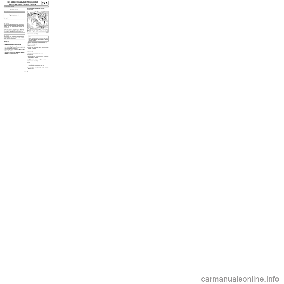
aRemove the roof middle cross member bolts (2) .
aRemove the stops (3) .
aRoll the sun visors.
aRemove the « sunroof sun visors - roof centre cross
member » assembly.
REFITTING
I - REFITTING OPERATION FOR PART
CONCERNED
aBring together the « sunroof sun visors - roof centre
cross member » assembly.
aEngage the sun visors into the guide runners.
aUnroll the sun visors fully.
aRefit:
-the stops (3) ,
-the roof middle cross member bolts (2) .
aTorque tighten the roof middle cross member
bolts (4 N.m ). Equipment required
Diagnostic tool
Tightening torquesm
roof middle cross mem-
ber bolts4 N.m
IMPORTANT
To avoid any risk of triggering when working on or
near a pyrotechnic component (airbags or preten-
sioners), lock the airbag computer using the dia-
gnostic tool.
When this function is activated, all the trigger lines
are inhibited and the airbag warning light on the ins-
trument panel lights up contin uously (ignition on).
IMPORTANT
Never handle the pyrotechnic systems (pretensio-
ners or airbags) near to a source of heat or naked
flame - they may be triggered.
121222
Note:
Do not remove the bolts (1) from the visor retai-
ning yokes; the visors are connected to the mid-
dle cross member.
Page 37 of 95
54A-7
WINDOWS
Sunroof fixed window: Removal - Refitting
54A
REMOVAL
I - REMOVAL PREPARATION OPERATION
aLock the airbag computer using the Diagnostic tool
(see Fault finding - Replacement of components)
(MR 413, 88C, Airbags and seat belt pretensioners).
aDisconnect the battery (see Battery: Removal - Re-
fitting) (MR 411, 80A, Battery).
aRemove:
-the headlining (see Headlining: Removal - Refit-
ting) (MR 412, 71A, Body internal trim),
-the roof protection strips (see 55A, Exterior pro-
tection, Roof protection strip: Removal - Refit-
ting, page 55A-17) .
aProtect:
-the sunroof's fixed window surround and the rear
section of the roof using masking tape,
-the inside of the vehicle.II - REMOVAL OPERATION FOR PART
CONCERNED
aCut the cement bead; this operation requires two
people.
aRemove the fixed window from the sunroof.
REFITTING
I - REFITTING PREPARATIONS OPERATION
aPosition the new shims on the sunroof operating me-
chanism.
aFor preparation and bonding (see Technical Note
560A).
II - REFITTING OPERATION FOR PART
CONCERNED
aBond the sunroof fixed window using the specific
support (this operation requires two people):
-Support: PARV 202,
-set of arch supports: APARV 200 ESP. Equipment required
Diagnostic tool
IMPORTANT
To avoid any risk of triggering when working on or
near a pyrotechnic component (airbags or preten-
sioners), lock the airbag computer using the dia-
gnostic tool.
When this function is activated, all the trigger lines
are inhibited and the airbag warning light on the ins-
trument panel lights up contin uously (ignition on).
IMPORTANT
Never handle the pyrotechnic systems (pretensio-
ners or airbags) near to a source of heat or naked
flame - they may be triggered.
121153
Page 41 of 95
55A-3
EXTERIOR PROTECTION
Front bumper: Stripping - Rebuilding
55A
STRIPPING
I - STRIPPING PREPARATION OPERATION
aRemove the front bumper (see 55A, Exterior pro-
tection, Front bumper: Removal - Refitting, page
55A-1) .
II - STRIPPING OPERATION FOR PART
CONCERNED
aRemove the front fog lights (depending on equip-
ment level) (see Front fog light: Removal - Refit-
ting) (MR 411, 80B, Headlights).
aNote the position of the electrical wiring (depending
on equipment level).
aRemove the electrical wiring (depending on equip-
ment level).
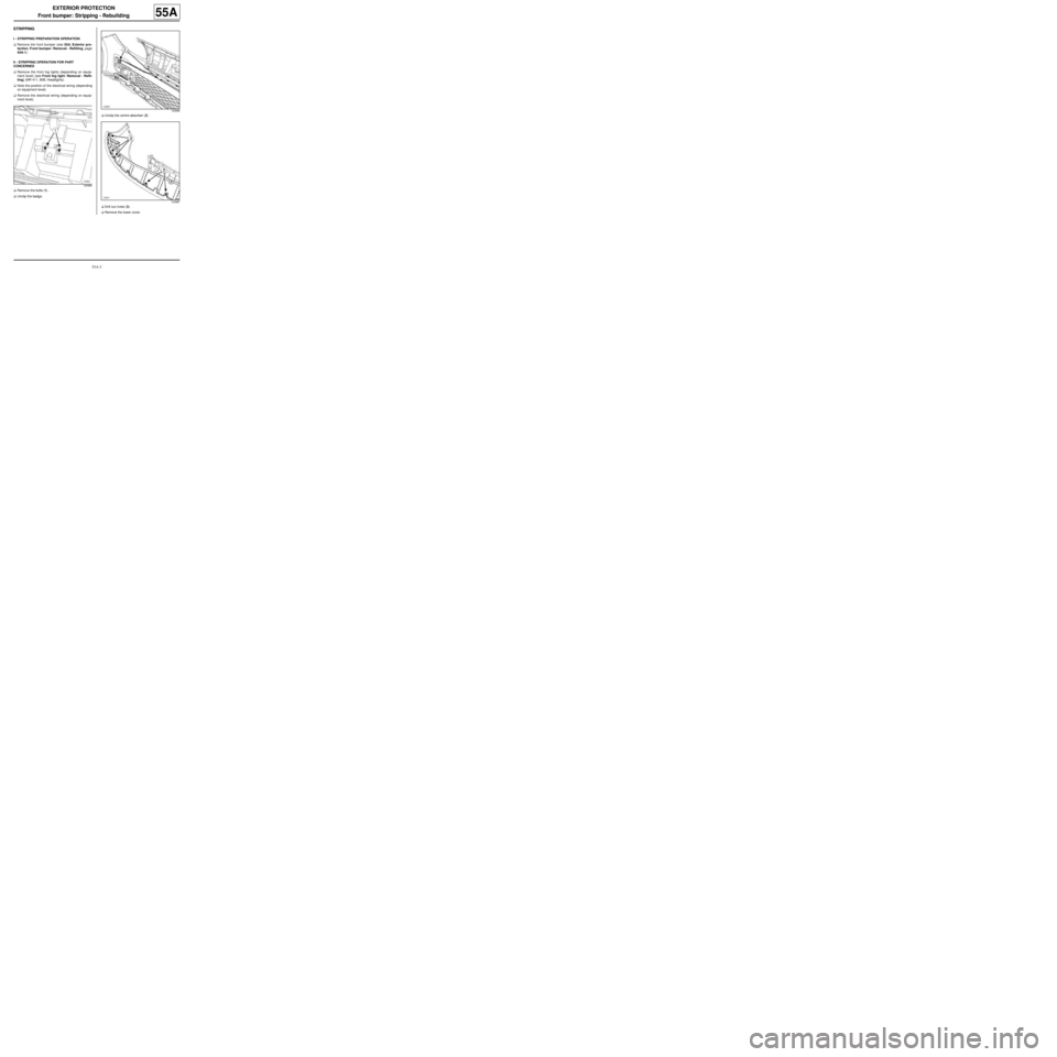
aRemove the bolts (1) .
aUnclip the badge.aUnclip the centre absorber (2) .
aDrill out rivets (3) .
aRemove the lower cover.
120886
120888
120887
Page 43 of 95

55A-5
EXTERIOR PROTECTION
Front bumper: Stripping - Rebuilding
55A
aInsert rivets into the lower cover at (3) .
aClip on:
-the central absorber (2) ,
-the badge.
aRefit:
-the bolts (1) ,
-the electrical wiring (depending on equipment le-
vel),
-the front fog lights (depending on the equipment le-
vel) (see Front fog light: Removal - Refitting)
(MR 411, 80B, Headlights).
II - FINAL OPERATION.
aRefit the front bumper (see 55A, Exterior protec-
tion, Front bumper: Removal - Refitting, page
55A-1) .
Page 44 of 95
55A-6
EXTERIOR PROTECTION
Front bumper: Stripping - Rebuilding
C44, and EQUIPMENT LEVEL SPORT
55A
STRIPPING
I - STRIPPING PREPARATION OPERATION
aRemove the front bumper (see 55A, Exterior pro-
tection, Front bumper: Removal - Refitting, page
55A-1) .
II - STRIPPING OPERATION FOR PART
CONCERNED
aRemove the front fog lights (see Front fog light:
Removal - Refitting) (80B, Headlights).
aRemove the bolts (1) .
aUnclip the badge.aUnclip the centre absorber (2) .
120886
132040
Page 47 of 95

55A-9
EXTERIOR PROTECTION
Front bumper: Stripping - Rebuilding
C44, and EQUIPMENT LEVEL SPORT
55A
II - REBUILDING OPERATION FOR PART
CONCERNED
aPlace the decorative strip to be bonded on the front
bumper and centre it visually.
aStick the decorative strip down taking care to keep it
properly aligned.
aClip:
-the « front side extender - front extender - fog light
support » assembly,
-the aerodynamic component.
aDrill a hole at each clip position (7) using a ∅ 4.5 mm
drill bit.
aRivet the aerodynamic component.
aClip the lower grille and the radiator grille onto the
tabs provided using the clips (part no.: 77 03 076
037).
aRefit the diffuser.
aClip on the lower absorber (4) .
aRefit new rivets.
aClip:
-the central absorber (2) ,
-the badge.
aRefit the front fog lights (see Front fog light: Remo-
val - Refitting) (80B, Headlights).
III - FINAL OPERATION.
aRefit the front bumper (see 55A, Exterior protec-
tion, Front bumper: Removal - Refitting, page
55A-1) .
Page 48 of 95
55A-10
EXTERIOR PROTECTION
Rear bumper: Removal - Refitting
55A
REMOVAL
I - REMOVAL PREPARATION OPERATION
aPosition the vehicle on a two-post lift (see Vehicle:
Towing and lifting) (02A, Lifting equipment).
aRemove the rear lights (see Rear wing light: Re-
moval - Refitting) (81A, Rear lighting).
aUnclip the side extenders of the rear bumper (1)
using a flat-blade screwdriver.II - OPERATION FOR REMOVAL OF PART
CONCERNED
aRemove the bolts (2) .
aRemove the bolts (3) . EQ UIPMENT LEVEL SPORT
132041
119260
119255
Page 50 of 95
55A-12
EXTERIOR PROTECTION
Rear bumper: Removal - Refitting
55A
aDisconnect the proximity sensor connector.
REFITTING
I - REFITTING OPERATION FOR PART
CONCERNED
aConnect the proximity sensor connector.
aConnect the number plate light connector.
aRefit the rear bumper (this operation requires two
people).
II - FINAL OPERATION
aClip on the side extenders of the rear bumper in or-
der (7) , (8) , (9) , (10) , (11) .
aRefit the rear lights (see Rear wing light: Removal
- Refitting) (81A, Rear lighting).aCarry out a function test on all functions.
REAR PROXIMITY RADAR
REAR PROXIMITY RADAR
EQ UIPMENT LEVEL SPORT
132043
Page 51 of 95
55A-13
EXTERIOR PROTECTION
Rear bumper: Stripping - Rebuilding
55A
STRIPPING
I - STRIPPING PREPARATION OPERATION
aRemove the rear bumper (see 55A, Exterior pro-
tection, Rear bumper: Removal - Refitting, page
55A-10) .
II - STRIPPING OPERATION FOR PART
CONCERNED
aRemove the proximity radars (see Proximity radar:
Removal - Refitting) (87F, Parking distance con-
trol).
aRemove:
-the number plate lights (see Number plate light:
Removal - Refitting) (81A, Rear lighting),
-the electrical wiring.
aUnclip the outer impact strips.
REBUILDING
I - REBUILDING OPERATION FOR PART
CONCERNED
aClip on the outer impact strips.
aRefit:
-the electrical wiring,
-the number plate lights (see Number plate light:
Removal - Refitting) (81A, Rear lighting).
aRefit the proximity radars (see Proximity radar: Re-
moval - Refitting) (87F, Parking distance control).
II - FINAL OPERATION.
aRefit the rear bumper (see 55A, Exterior protec-
tion, Rear bumper: Removal - Refitting, page
55A-10) . REAR PROXIMITY RADAR
EQUIPMENT LEVEL EA0 or EQUIPMENT LEVEL
EA1 or EQUIPMENT LEVEL EA3 or EQUIPMENT
LEVEL EA5
120801
EQUIPMENT LEVEL EA0 or EQUIPMENT LEVEL
EA1 or EQUIPMENT LEVEL EA3 or EQUIPMENT
LEVEL EA5
REAR PROXIMITY RADAR