ESP RENAULT TWINGO 2009 2.G Sequential Transmission Workshop Manual
[x] Cancel search | Manufacturer: RENAULT, Model Year: 2009, Model line: TWINGO, Model: RENAULT TWINGO 2009 2.GPages: 138
Page 3 of 138
21B-3
MR-413-X44-21B000$059.mif
V2
Vdiag No: 04SEQUENTIAL GEARBOX
Fault finding - Introduction21B
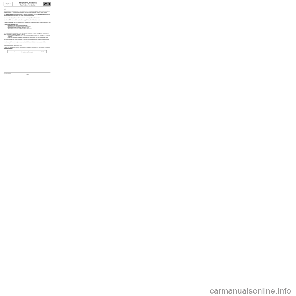
Faults
Faults are declared as either present or stored (depending on whether they appeared in a certain context and have
disappeared since, or whether they remain present but have not been diagnosed within the current context).
The present or stored status of faults should be taken into consideration when the diagnostic tool is switched on
after the + after ignition feed (without any system components being active).
For a present fault, apply the procedure described in the Interpretation of faults section.
For a stored fault, note the faults displayed and apply the instructions in the Notes section.
If the fault is confirmed when the instructions in the Notes section are applied, the fault is present. Deal with the fault
If the fault is not confirmed, check:
–the electrical lines which correspond to the fault,
–the connectors on these lines (corrosion, bent pins, etc.),
–the resistance of the component detected as faulty,
–the condition of the wires (melted or split insulation, wear).
Conformity check
The aim of the conformity check is to check data that does not produce a fault on the diagnostic tool because the
data is inconsistent. Therefore, this stage is used to:
–carry out fault finding on faults that do not have a fault display, and which may correspond to a customer
complaint.
–check that the system is operating correctly and that there is no risk of a fault recurring after repairs.
This section gives the fault finding procedures for statuses and parameters and the conditions for checking them.
If a status is not behaving normally or a parameter is outside the permitted tolerance values, consult the
corresponding fault finding page.
Customer complaints - Fault finding chart
If the test with the diagnostic tool is OK but the customer complaint is still present, the fault should be processed by
customer complaint.
A summary of the overall procedure to follow is provided on the following page
in the form of a flow chart.
Page 5 of 138
21B-5
MR-413-X44-21B000$059.mif
V2
Vdiag No: 04SEQUENTIAL GEARBOX
Fault finding - Introduction21B
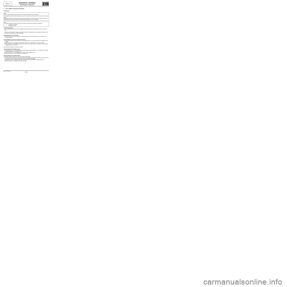
4. FAULT FINDING PROCEDURE (CONTINUED)
Wiring check
Fault finding problems
Disconnecting the connectors and/or manipulating the wiring harness may temporarily remove the cause of a
fault.
Electrical measurements of voltage, resistance and insulation are generally correct, especially if the fault is not
present when the analysis is made (stored fault).
Visual inspection of the connection
●Check that the connector is connected correctly and that the male and female parts of the connection are
correctly coupled.
Visual inspection of the area around the connection
●Check the condition of the mounting (pin, strap, adhesive tape, etc.), that the connectors are attached to the
vehicle.
●Check that there is no damage to the wiring trim (sheath, foam, adhesive tape, etc.) near the wiring.
●Check that there is no damage to the electrical wires at the connector outputs, in particular on the insulating
material (wear, cuts, burns, etc.).
Disconnect the connector to continue the checks.
Visual inspection of the plastic casing
●Check that there is no mechanical damage (casing crushed, cracked, broken, etc.), in particular to the fragile
components (lever, lock, openings, etc.).
●Check that there is no heat damage (casing melted, darker, deformed, etc.).
●Check that there are no stains (grease, mud, liquid, etc.).
Visual inspection of the metal contacts
(The female contact is called CLIP. The male contact is called TAB.)
●Check that there are no bent contacts (the contact is not inserted correctly and can come out of the back of the
connector). The spring contact of the connector when pulling the wire slightly.
●Check that there is no damage (folded tabs, clips open too wide, blackened or melted contact, etc.).
●Check that there is no oxidation on the metal contacts. Note:
Carry out each requested check visually. Do not remove a connector if it is not required.
Note:
Repeated connections and disconnections alter the functionality of the connectors and increase the risk of poor
electrical contact. Limit the number of connections/disconnections as much as possible.
Note:
The check is carried out on the 2 parts of the connection. There may be two types of connections:
–Connector / Connector
–Connector / Device
Page 23 of 138
21B-23
MR-413-X44-21B000$354.mif
V2
Vdiag No: 04SEQUENTIAL GEARBOX
Fault finding - Fault summary table21B
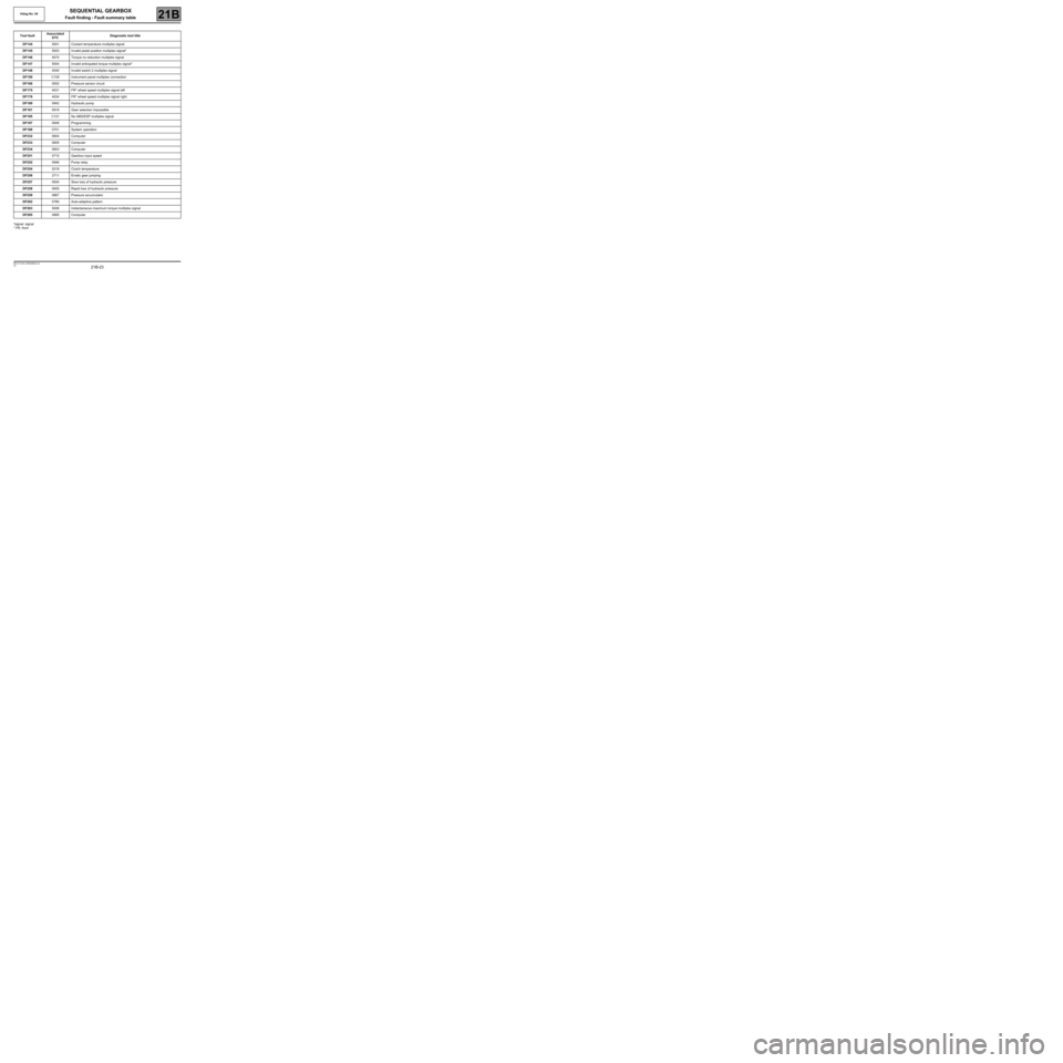
*signal: signal
* FR: frontTool faultAssociated
DTCDiagnostic tool title
DF1445001 Coolant temperature multiplex signal
DF1455003 Invalid pedal position multiplex signal*
DF1464074 Torque no reduction multiplex signal
DF1475004 Invalid anticipated torque multiplex signal*
DF1484040 Invalid switch 2 multiplex signal
DF150C155 Instrument panel multiplex connection
DF1660932 Pressure sensor circuit
DF1754031 FR* wheel speed multiplex signal left
DF1764034 FR* wheel speed multiplex signal right
DF1800942 Hydraulic pump
DF1810919 Gear selection impossible
DF185C121 No ABS/ESP multiplex signal
DF1870949 Programming
DF1880701 System operation
DF2320604 Computer
DF2330605 Computer
DF2340603 Computer
DF2510715 Gearbox input speed
DF2520946 Pump relay
DF2540218 Clutch temperature
DF2562711 Erratic gear jumping
DF2570934 Slow loss of hydraulic pressure
DF2580935 Rapid loss of hydraulic pressure
DF2590867 Pressure accumulator
DF2620780 Auto-adaptive pattern
DF2635006 Instantaneous maximum torque multiplex signal
DF2650885 Computer
Page 28 of 138
21B-28
MR-413-X44-21B000$413.mif
V2
SEQUENTIAL GEARBOX
Fault finding - Interpretation of faults
Vdiag No.: 04
21B
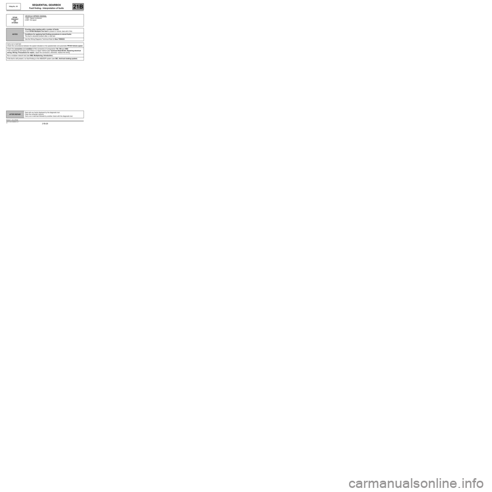
DF048
PRESENT
OR
STOREDVEHICLE SPEED SIGNAL
1.DEF: Signal incoherent
2.DEF: No signal
NOTESPriorities when dealing with a number of faults:
If fault DF062 Multiplex line fault is present or stored, deal with it first.
Conditions for applying fault finding procedures to stored faults:
The fault is declared present after a road test.
Use the Wiring Diagrams Technical Note for New TWINGO.
Carry out a road test.
Check the concordance between the speed indicated on the speedometer and parameter PR105 Vehicle speed.
Check the connection and condition of the connectors of components 119, 120 and 1094.
If the connector(s) are faulty and if there is a repair method (see Technical Note 6015A, Repairing electrical
wiring, W iring: Precautions for repair), repair the connectors; otherwise, replace the wiring.
Run a multiplex network test (see 88B, Multiplexing, Introduction).
If the fault is still present, run fault finding on the ABS/ESP system (see 38C, Anti-lock braking system).
AFTER REPAIRDeal with any faults displayed by the diagnostic tool.
Clear the computer memory.
Carry out a road test followed by another check with the diagnostic tool.
BVRJH1_V04_DF048
Page 29 of 138
21B-29
MR-413-X44-21B000$413.mif
V2
SEQUENTIAL GEARBOX
Fault finding - Interpretation of faults
Vdiag No.: 04
21B
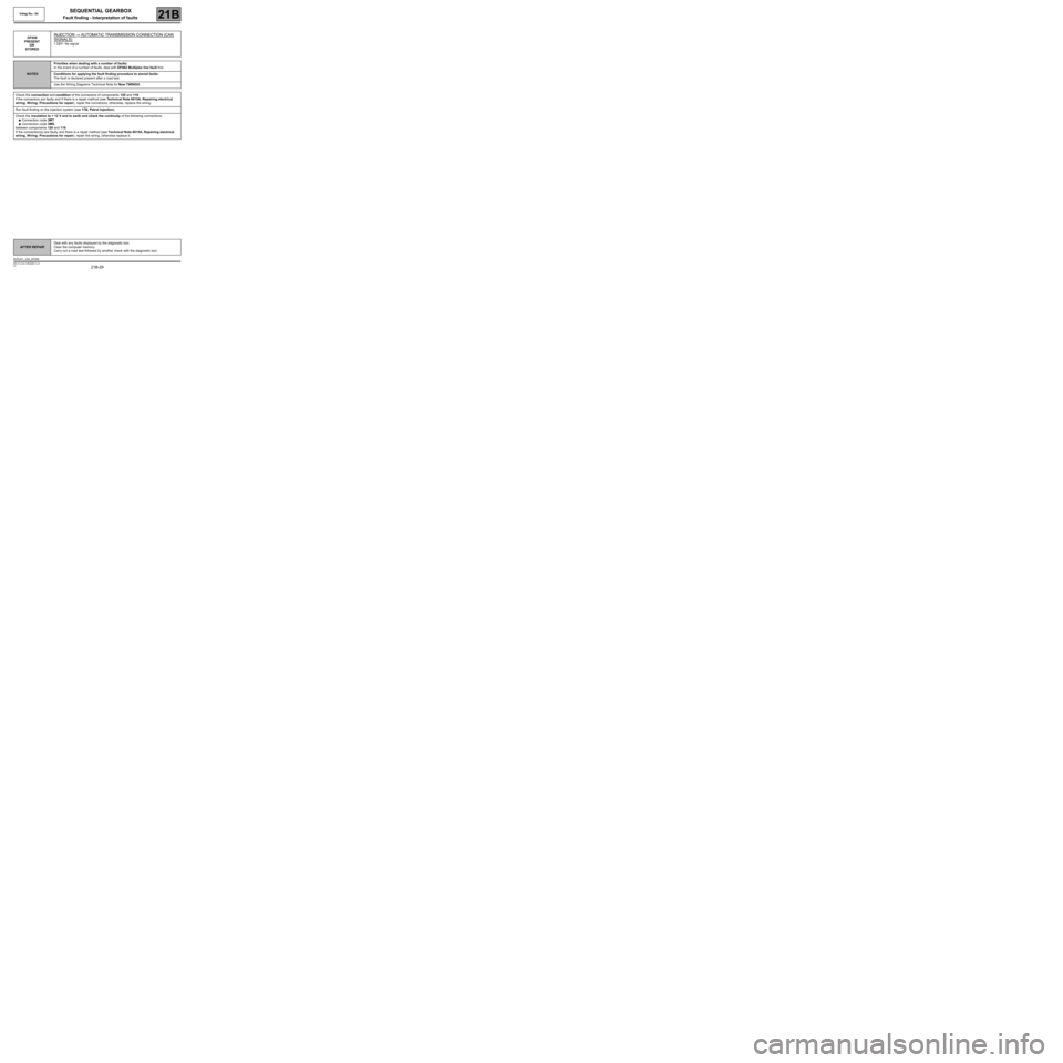
DF059
PRESENT
OR
STOREDINJECTION → AUTOMATIC TRANSMISSION CONNECTION (CAN
SIGNALS)
1.DEF: No signal
NOTESPriorities when dealing with a number of faults:
In the event of a number of faults, deal with DF062 Multiplex line fault first.
Conditions for applying the fault finding procedure to stored faults:
The fault is declared present after a road test.
Use the Wiring Diagrams Technical Note for New TWINGO.
Check the connection and condition of the connectors of components 120 and 119.
If the connectors are faulty and if there is a repair method (see Technical Note 6015A, Repairing electrical
wiring, W iring: Precautions for repair), repair the connectors; otherwise, replace the wiring.
Run fault finding on the injection system (see 17B, Petrol Injection).
Check the insulation to + 12 V and to earth and check the continuity of the following connections:
●Connection code 3MT,
●Connection code 3MS,
between components 120 and 119.
If the connection(s) are faulty and there is a repair method (see Technical Note 6015A, Repairing electrical
wiring, W iring: Precautions for repair), repair the wiring, otherwise replace it.
AFTER REPAIRDeal with any faults displayed by the diagnostic tool.
Clear the computer memory.
Carry out a road test followed by another check with the diagnostic tool.
BVRJH1_V04_DF059
Page 31 of 138
21B-31
MR-413-X44-21B000$413.mif
V2
SEQUENTIAL GEARBOX
Fault finding - Interpretation of faults
Vdiag No.: 04
21B
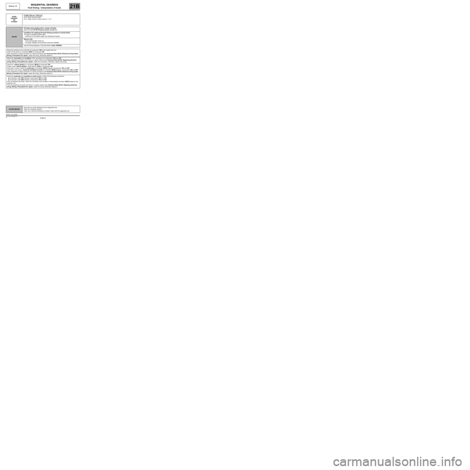
DF065
PRESENT
OR
STOREDPUMP RELAY CIRCUIT
CC.0: Short circuit to earth
CO.1: Open circuit or short circuit to + 12 V
NOTESPriorities when dealing with a number of faults:
Deal with fault DF166 Pressure sensor circuit first.
Conditions for applying the fault finding procedure to stored faults:
The fault is declared present after:
–switching on the ignition again and starting the engine.
Special note:
–Fault warning light comes on.
–Any gear changes and automatic mode are inhibited.
Use the Wiring Diagrams Technical Note for New TWINGO.
Check the presence and conformity of component 762 in the engine fuse box.
Check for the earth on connection MAS of component 792.
If the connection is faulty and there is a repair procedure (see Technical Note 6015A, Electrical wiring repair,
Wiring: Precautions for repair), repair the wiring, otherwise replace it.
Check the connection and condition of the connectors of components 762 and 120.
If the connectors are faulty and if there is a repair method (see Technical Note 6015A, Repairing electrical
wiring, W iring: Precautions for repair), repair the connectors; otherwise, replace the wiring.
Check for + before ignition on connection BP36 of component 762.
If there is no + before ignition, check fuse F1 (30A) on component 597.
If the fuse is correct, check the continuity of connection BP36 between components 762 and 597.
If the fuse is not correct, check the insulation to earth of connection BP36 between components 762 and 597.
If the connection is faulty and there is a repair procedure (see Technical Note 6015A, Electrical wiring repair,
Wiring: Precautions for repair), repair the wiring, otherwise replace it.
Check the continuity and insulation to earth and to + 12 V of the following connections:
●Connection code 5AF between components 762 and 119.
●Connection code 5AE between components 762 and 724.
If the connections are faulty, check the connection and condition of intermediate connector R235 located on the
hydraulic unit.
If the connection(s) are faulty and there is a repair method (see Technical Note 6015A, Repairing electrical
wiring, W iring: Precautions for repair), repair the wiring, otherwise replace it.
AFTER REPAIRDeal with any faults displayed by the diagnostic tool.
Clear the computer memory.
Carry out a road test followed by another check with the diagnostic tool.
BVRJH1_V04_DF065
Page 42 of 138
21B-42
MR-413-X44-21B000$413.mif
V2
SEQUENTIAL GEARBOX
Fault finding - Interpretation of faults
Vdiag No.: 04
21B
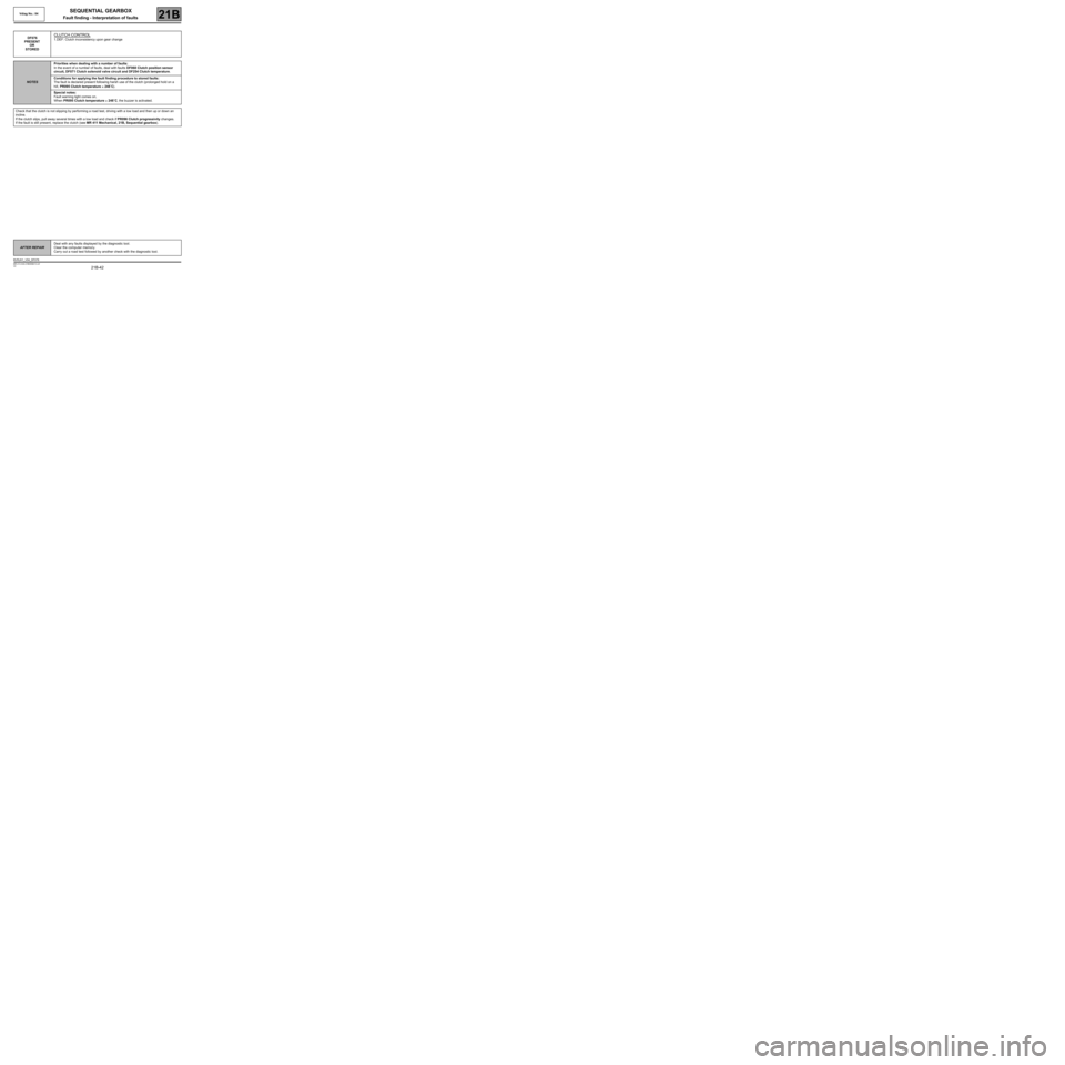
DF076
PRESENT
OR
STOREDCLUTCH CONTROL
1.DEF: Clutch inconsistency upon gear change
NOTESPriorities when dealing with a number of faults:
In the event of a number of faults, deal with faults DF068 Clutch position sensor
circuit, DF071 Clutch solenoid valve circuit and DF254 Clutch temperature.
Conditions for applying the fault finding procedure to stored faults:
The fault is declared present following harsh use of the clutch (prolonged hold on a
hill, PR095 Clutch temperature ≥ 248˚C).
Special notes:
Fault warning light comes on,
When PR095 Clutch temperature ≥ 248˚C, the buzzer is activated.
Check that the clutch is not slipping by performing a road test, driving with a low load and then up or down an
incline.
If the clutch slips, pull away several times with a low load and check if PR096 Clutch progressivity changes.
If the fault is still present, replace the clutch (see MR 411 Mechanical, 21B, Sequential gearbox).
AFTER REPAIRDeal with any faults displayed by the diagnostic tool.
Clear the computer memory.
Carry out a road test followed by another check with the diagnostic tool.
BVRJH1_V04_DF076
Page 43 of 138
21B-43
MR-413-X44-21B000$413.mif
V2
SEQUENTIAL GEARBOX
Fault finding - Interpretation of faults
Vdiag No.: 04
21B
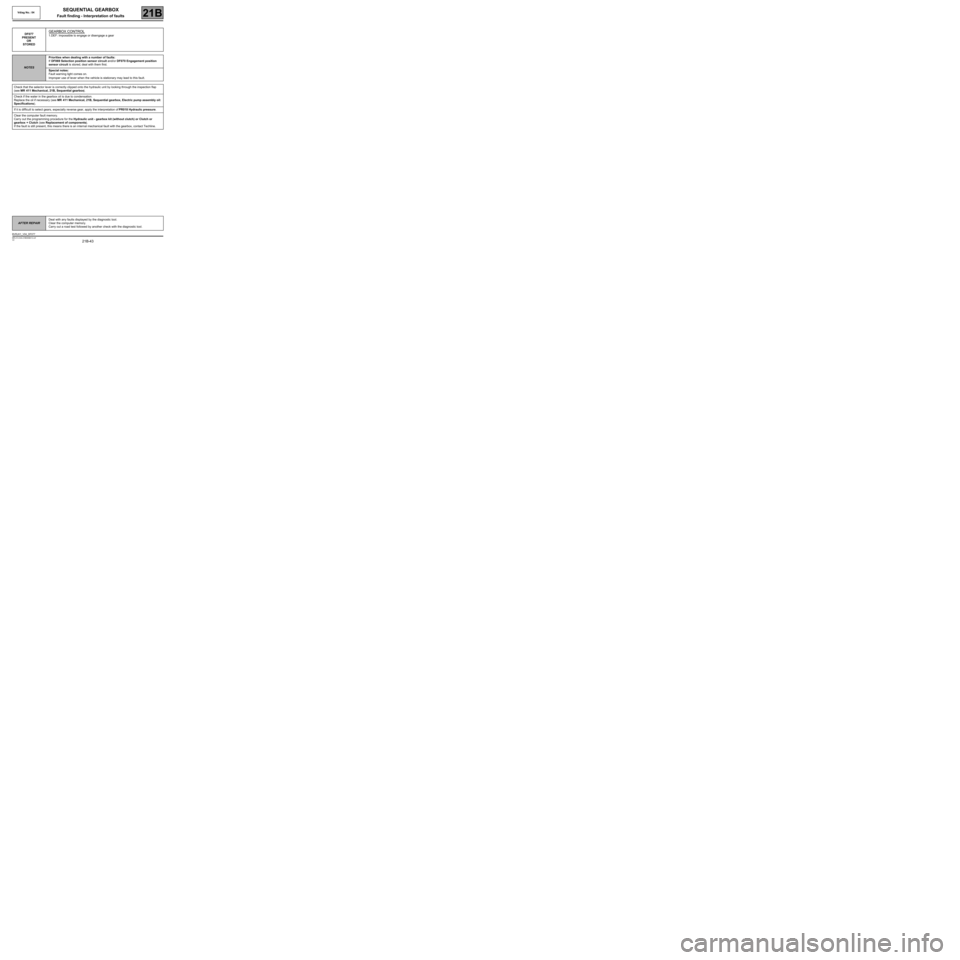
DF077
PRESENT
OR
STOREDGEARBOX CONTROL
1.DEF: Impossible to engage or disengage a gear
NOTESPriorities when dealing with a number of faults:
If DF069 Selection position sensor circuit and/or DF070 Engagement position
sensor circuit is stored, deal with them first.
Special notes:
Fault warning light comes on.
Improper use of lever when the vehicle is stationary may lead to this fault.
Check that the selector lever is correctly clipped onto the hydraulic unit by looking through the inspection flap
(see MR 411 Mechanical, 21B, Sequential gearbox).
Check if the water in the gearbox oil is due to condensation.
Replace the oil if necessary (see MR 411 Mechanical, 21B, Sequential gearbox, Electric pump assembly oil:
Specifications).
If it is difficult to select gears, especially reverse gear, apply the interpretation of PR018 Hydraulic pressure.
Clear the computer fault memory.
Carry out the programming procedure for the Hydraulic unit - gearbox kit (without clutch) or Clutch or
gearbox + Clutch (see Replacement of components).
If the fault is still present, this means there is an internal mechanical fault with the gearbox, contact Techline.
AFTER REPAIRDeal with any faults displayed by the diagnostic tool.
Clear the computer memory.
Carry out a road test followed by another check with the diagnostic tool.
BVRJH1_V04_DF077
Page 44 of 138
21B-44
MR-413-X44-21B000$413.mif
V2
SEQUENTIAL GEARBOX
Fault finding - Interpretation of faults
Vdiag No.: 04
21B
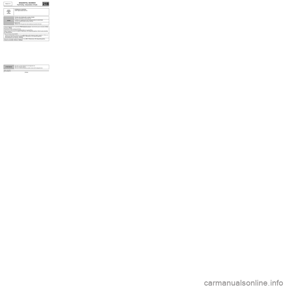
DF078
PRESENT
OR
STOREDHYDRAULIC CONTROL
1.DEF: Signal outside lower limit
NOTESPriorities when dealing with a number of faults:
Apply the interpretation of other faults first.
Conditions for applying the fault finding procedure to stored faults:
The fault is declared present during a road test.
Special note:
Improper use of the gear lever when stationary may lead to this fault.
Using the diagnostic tool, via parameter PR018 Hydraulic pressure, check that the pump is activated at 40 bar
and stops at 50 bar.
Pressure level below a pressure threshold.
Fault linked to a lack of oil (internal or external leak) or to a pump failure.
Repair or replace if necessary (see MR 411 Mechanical, 21B, Sequential gearbox, Electric pump assembly
oil: Specifications).
Case of excessive pump operation:
–Internal or external leak in the circuit. For an external leak, locate the leak and repair if necessary. If there is an
internal leak, replace the hydraulic unit (see MR 411 Mechanical, 21B, Sequential gearbox,
Electrohydraulic unit: Removal - Refitting).
If the fault is still present, replace the accumulator (see MR 411 Mechanical, 21B, Sequential gearbox,
Pressure accumulator: Removal - Refitting).
AFTER REPAIRDeal with any faults displayed by the diagnostic tool.
Clear the computer memory.
Carry out a road test followed by another check with the diagnostic tool.
BVRJH1_V04_DF078
Page 47 of 138
21B-47
MR-413-X44-21B000$413.mif
V2
SEQUENTIAL GEARBOX
Fault finding - Interpretation of faults
Vdiag No.: 04
21B
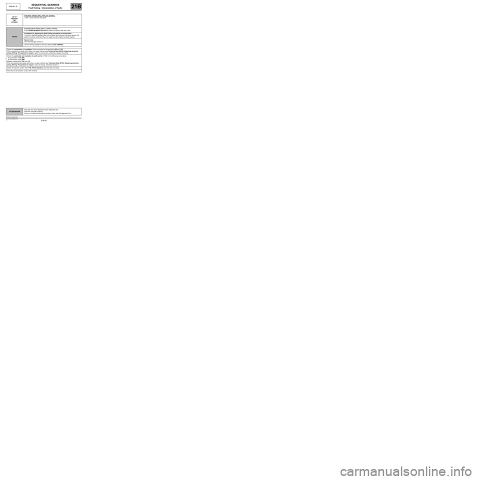
DF107
PRESENT
OR
STOREDENGINE SPEED MULTIPLEX SIGNAL
1.DEF: Communication disrupted
NOTESPriorities when dealing with a number of faults:
If fault DF062 Multiplex line fault is present or stored, deal with it first.
Conditions for applying the fault finding procedure to stored faults:
The fault is declared present after the computer fault memory has been cleared, the
ignition has been switched off and on again and the engine has been started.
Special note:
Fault warning light comes on.
Use the Wiring Diagrams Technical Note for New TWINGO.
Check the connection and condition of the connectors of components 120 and 119.
If the connectors are faulty and if there is a repair method (see Technical Note 6015A, Repairing electrical
wiring, W iring: Precautions for repair), repair the connectors; otherwise, replace the wiring.
Check the continuity and insulation to earth and to + 12 V on the following connections:
●Connection code 3MT,
●Connection code 3MS,
between components 120 and 119.
If the connection(s) are faulty and there is a repair method (see Technical Note 6015A, Repairing electrical
wiring, W iring: Precautions for repair), repair the wiring, otherwise replace it.
Check the injection system (see 17B, Petrol injection) and deal with any faults.
If the fault is still present, contact the Techline.
AFTER REPAIRDeal with any faults displayed by the diagnostic tool.
Clear the computer memory.
Carry out a road test followed by another check with the diagnostic tool.
BVRJH1_V04_DF107