lock RENAULT TWINGO 2009 2.G Sequential Transmission Workshop Manual
[x] Cancel search | Manufacturer: RENAULT, Model Year: 2009, Model line: TWINGO, Model: RENAULT TWINGO 2009 2.GPages: 138
Page 5 of 138
21B-5
MR-413-X44-21B000$059.mif
V2
Vdiag No: 04SEQUENTIAL GEARBOX
Fault finding - Introduction21B
4. FAULT FINDING PROCEDURE (CONTINUED)
Wiring check
Fault finding problems
Disconnecting the connectors and/or manipulating the wiring harness may temporarily remove the cause of a
fault.
Electrical measurements of voltage, resistance and insulation are generally correct, especially if the fault is not
present when the analysis is made (stored fault).
Visual inspection of the connection
●Check that the connector is connected correctly and that the male and female parts of the connection are
correctly coupled.
Visual inspection of the area around the connection
●Check the condition of the mounting (pin, strap, adhesive tape, etc.), that the connectors are attached to the
vehicle.
●Check that there is no damage to the wiring trim (sheath, foam, adhesive tape, etc.) near the wiring.
●Check that there is no damage to the electrical wires at the connector outputs, in particular on the insulating
material (wear, cuts, burns, etc.).
Disconnect the connector to continue the checks.
Visual inspection of the plastic casing
●Check that there is no mechanical damage (casing crushed, cracked, broken, etc.), in particular to the fragile
components (lever, lock, openings, etc.).
●Check that there is no heat damage (casing melted, darker, deformed, etc.).
●Check that there are no stains (grease, mud, liquid, etc.).
Visual inspection of the metal contacts
(The female contact is called CLIP. The male contact is called TAB.)
●Check that there are no bent contacts (the contact is not inserted correctly and can come out of the back of the
connector). The spring contact of the connector when pulling the wire slightly.
●Check that there is no damage (folded tabs, clips open too wide, blackened or melted contact, etc.).
●Check that there is no oxidation on the metal contacts. Note:
Carry out each requested check visually. Do not remove a connector if it is not required.
Note:
Repeated connections and disconnections alter the functionality of the connectors and increase the risk of poor
electrical contact. Limit the number of connections/disconnections as much as possible.
Note:
The check is carried out on the 2 parts of the connection. There may be two types of connections:
–Connector / Connector
–Connector / Device
Page 28 of 138
21B-28
MR-413-X44-21B000$413.mif
V2
SEQUENTIAL GEARBOX
Fault finding - Interpretation of faults
Vdiag No.: 04
21B
DF048
PRESENT
OR
STOREDVEHICLE SPEED SIGNAL
1.DEF: Signal incoherent
2.DEF: No signal
NOTESPriorities when dealing with a number of faults:
If fault DF062 Multiplex line fault is present or stored, deal with it first.
Conditions for applying fault finding procedures to stored faults:
The fault is declared present after a road test.
Use the Wiring Diagrams Technical Note for New TWINGO.
Carry out a road test.
Check the concordance between the speed indicated on the speedometer and parameter PR105 Vehicle speed.
Check the connection and condition of the connectors of components 119, 120 and 1094.
If the connector(s) are faulty and if there is a repair method (see Technical Note 6015A, Repairing electrical
wiring, W iring: Precautions for repair), repair the connectors; otherwise, replace the wiring.
Run a multiplex network test (see 88B, Multiplexing, Introduction).
If the fault is still present, run fault finding on the ABS/ESP system (see 38C, Anti-lock braking system).
AFTER REPAIRDeal with any faults displayed by the diagnostic tool.
Clear the computer memory.
Carry out a road test followed by another check with the diagnostic tool.
BVRJH1_V04_DF048
Page 46 of 138
21B-46
MR-413-X44-21B000$413.mif
V2
SEQUENTIAL GEARBOX
Fault finding - Interpretation of faults
Vdiag No.: 04
21B
DF082
PRESENT
OR
STOREDBRAKE LIGHTS SWITCH CIRCUIT
1.DEF: Signal incoherent
NOTESSpecial note:
Indicator light comes on if the fault is present when driving twice in succession.
Use the Wiring Diagrams Technical Note for New TWINGO.
Check for the presence, condition and correct positioning of the 15A fuse for the brake lights in the passenger
compartment fuse box.
Check the connection and condition of the connectors of components 160 and 119.
If the connectors are faulty and if there is a repair method (see Technical Note 6015A, Repairing electrical
wiring, W iring: Precautions for repair), repair the connectors; otherwise, replace the wiring.
Check the fitting and adjustment of component 160 on the pedal assembly.
Pedal depressed:
Check the continuity between connections AP10 (track 2) and 65A of component 160.
Check the insulation between connections AP10 (track 4) and 5A of component 160.
If the checks are incorrect, replace the switch (see MR 411 Mechanical, 83D Cruise control, Brake light
switch: Removal - Refitting).
Pedal released:
Check the insulation between connections AP10 (track 2) and 65A of component 160.
Check the insulation between connections AP10 (track 4) and 5A of component 160.
If the checks are incorrect, replace the switch (see MR 411 Mechanical, 83D Cruise control, Brake light
switch: Removal - Refitting).
Check the continuity and insulation from earth of the following connection:
●Connection code 65A between components 160 and 119.
If the connection is faulty, check the connection and condition of intermediate connector R67 located near the
engine fuse and relay box.
If the connection is faulty and there is a repair procedure (see Technical Note 6015A, Electrical wiring repair,
Wiring: Precautions for repair), repair the wiring, otherwise replace it.
If the fault is still present, perform fault finding of the following computers:
●The UCH (see 87B, Passenger compartment connection unit).
●The injection computer (see 17B, Petrol injection).
●The ABS computer (see 38C, Anti-lock braking system).
AFTER REPAIRDeal with any faults displayed by the diagnostic tool.
Clear the computer memory.
Carry out a road test followed by another check with the diagnostic tool.
BVRJH1_V04_DF082
Page 51 of 138
21B-51
MR-413-X44-21B000$413.mif
V2
SEQUENTIAL GEARBOX
Fault finding - Interpretation of faults
Vdiag No.: 04
21B
* RR: rearDF117
DF118
PRESENT
OR
STORED
REAR LEFT-HAND WHEEL SPEED MULTIPLEX SIGNAL LEFT
REAR LEFT-HAND WHEEL SPEED MULTIPLEX SIGNAL RIGHT
1.DEF: Communication disrupted
NOTESPriorities when dealing with a number of faults:
If fault DF062 Multiplex line fault is present or stored, deal with it first.
Conditions for applying the fault finding procedure to stored faults:
The fault is declared present after a road test.
Special note:
–RR left-hand wheel speed multiplex signal = Rear left-hand wheel speed
multiplex signal.
–RR right-hand wheel speed multiplex signal = Rear right-hand wheel speed
multiplex signal.
Use the Wiring Diagrams Technical Note for New TWINGO.
Check the connection and condition of the connectors of components 120, 1094 and 119.
If the connectors are faulty and if there is a repair method (see Technical Note 6015A, Repairing electrical
wiring, W iring: Precautions for repair), repair the connectors; otherwise, replace the wiring.
Run a multiplex network test (see 88B, Multiplexing).
Check the injection system (see 17B, Petrol injection) and deal with any faults.
If the fault is still present, run fault finding on the ABS/ESP system (see 38C, Anti-lock braking system).
AFTER REPAIRDeal with any faults displayed by the diagnostic tool.
Clear the computer memory.
Carry out a road test followed by another check with the diagnostic tool.
BVRJH1_V04_DF117 / BVRJH1_V04_DF118
Page 61 of 138
21B-61
MR-413-X44-21B000$472.mif
V2
SEQUENTIAL GEARBOX
Fault finding - Interpretation of faults
Vdiag No: 04
21B
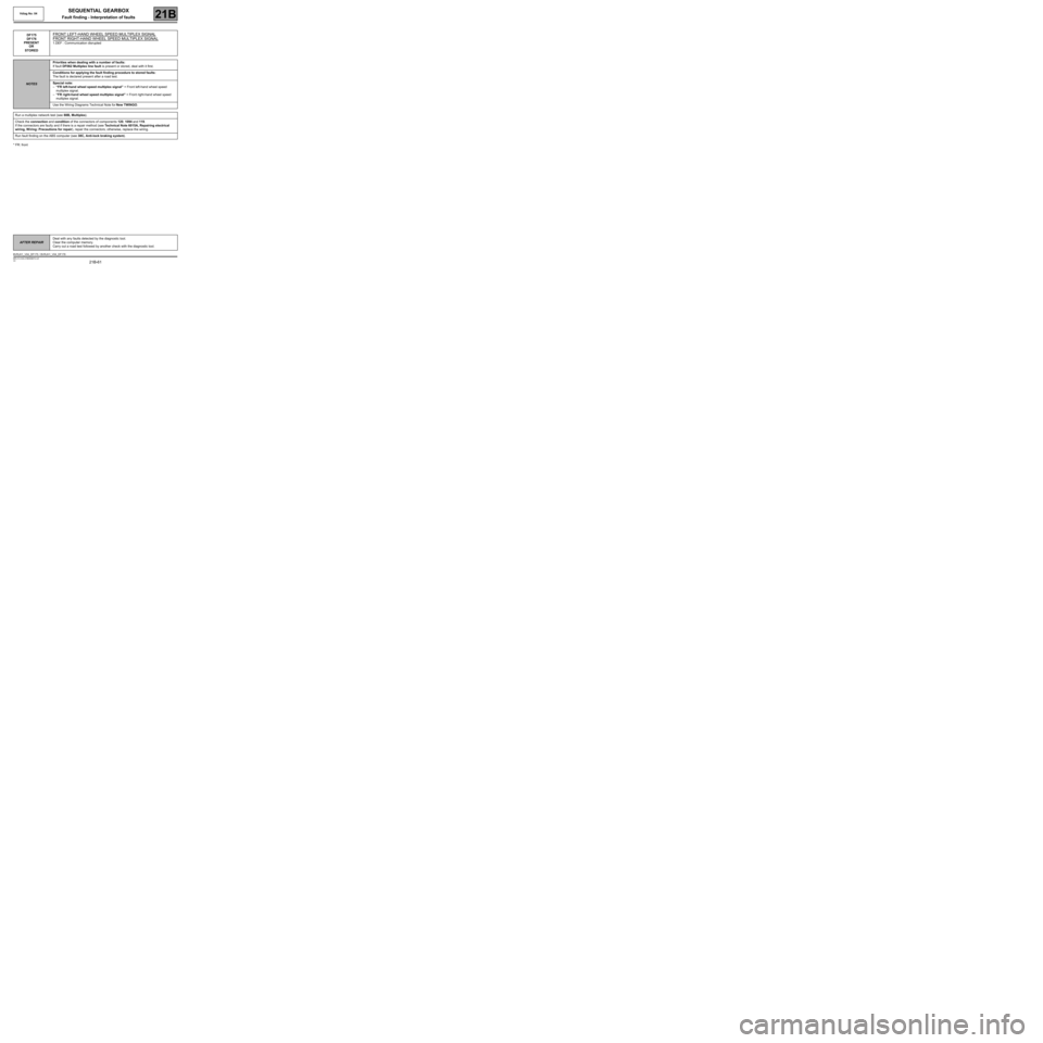
* FR: frontDF175
DF176
PRESENT
OR
STORED
FRONT LEFT-HAND WHEEL SPEED MULTIPLEX SIGNAL
FRONT RIGHT-HAND WHEEL SPEED MULTIPLEX SIGNAL
1.DEF : Communication disrupted
NOTESPriorities when dealing with a number of faults:
If fault DF062 Multiplex line fault is present or stored, deal with it first.
Conditions for applying the fault finding procedure to stored faults:
The fault is declared present after a road test.
Special note:
–“FR left-hand wheel speed multiplex signal” = Front left-hand wheel speed
multiplex signal.
–“FR right-hand wheel speed multiplex signal” = Front right-hand wheel speed
multiplex signal.
Use the Wiring Diagrams Technical Note for New TWINGO.
Run a multiplex network test (see 88B, Multiplex).
Check the connection and condition of the connectors of components 120, 1094 and 119.
If the connectors are faulty and if there is a repair method (see Technical Note 6015A, Repairing electrical
wiring, W iring: Precautions for repair), repair the connectors; otherwise, replace the wiring.
Run fault finding on the ABS computer (see 38C, Anti-lock braking system).
AFTER REPAIRDeal with any faults detected by the diagnostic tool.
Clear the computer memory.
Carry out a road test followed by another check with the diagnostic tool.
BVRJH1_V04_DF175 / BVRJH1_V04_DF176
Page 64 of 138
21B-64
MR-413-X44-21B000$472.mif
V2
SEQUENTIAL GEARBOX
Fault finding - Interpretation of faults
Vdiag No: 04
21B
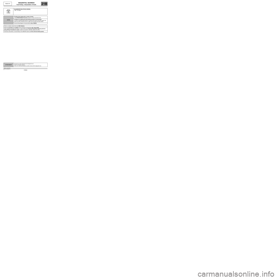
DF185
PRESENT
OR
STOREDNO ABS/ESP MULTIPLEX SIGNAL
1.DEF : No signal
NOTESPriorities when dealing with a number of faults:
If fault DF062 Multiplex line fault is present or stored, deal with it first.
Conditions for applying the fault finding procedure to stored faults:
The fault is declared present after the computer fault memory has been cleared, the
ignition has been switched off and on again and the engine has been started.
Use the Wiring Diagrams Technical Note for New TWINGO.
Perform a multiplex network test (see 88B, Multiplex).
Check the connection and condition of the connectors of components 120, 119 and 1094.
If the connectors are faulty and if there is a repair method (see Technical Note 6015A, Repairing electrical
wiring, W iring: Precautions for repair), repair the connectors; otherwise, replace the wiring.
If the fault is still present, run fault finding on the ABS/ESP system (see 38C, Anti-lock braking system).
AFTER REPAIRDeal with any faults detected by the diagnostic tool.
Clear the computer memory.
Carry out a road test followed by another check with the diagnostic tool.
BVRJH1_V04_DF185
Page 81 of 138
21B-81
MR-413-X44-21B000$649.mif
V2
SEQUENTIAL GEARBOX
Fault finding - Interpretation of statuses
Vdiag No: 04
21B
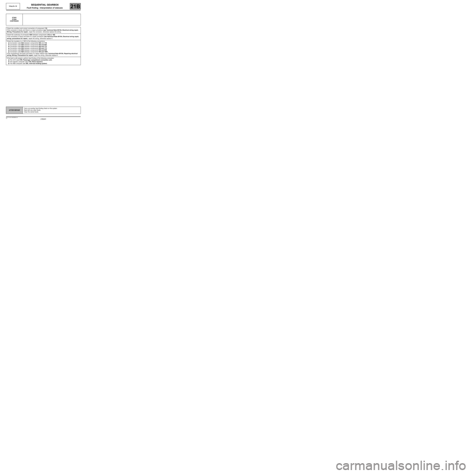
ET003
ET004
CONTINUED
Check the condition and correct connection of component 119.
If the connector is faulty and there is a repair procedure (see Technical Note 6015A, Electrical wiring repair,
Wiring: Precautions for repair), repair the connector, otherwise replace the wiring.
Check the continuity of connection 65A between components 119 and 160.
If the connection is faulty and there is a repair procedure (see Technical Note 6015A, Electrical wiring repair,
wiring: precautions for repair), repair the wiring, otherwise replace it.
Check the insulation to + 12 V of the following connections:
●Connection code 65A between components 160 and 119.
●Connection code 65A between components 160 and 645.
●Connection code 65A between components 160 and 172.
●Connection code 65A between components 160 and 173.
●Connection code 65A between components 160 and 639.
●Connection code 65A between components 160 and 1094.
If the connection(s) are faulty and there is a repair method (see Technical Note 6015A, Repairing electrical
wiring, W iring: Precautions for repair), repair the wiring, otherwise replace it.
If the fault is still present, perform fault finding of the following computers:
●The UCH (see 87B, Passenger compartment connection unit).
●The injection computer (see 17B, Petrol injection).
●The ABS computer (see 38C, Anti-lock braking system).
AFTER REPAIRCarry out another fault finding check on the system.
Deal with any other faults.
Clear the stored faults.
Page 116 of 138
21B-116
MR-413-X44-21B000$767.mif
V2
SEQUENTIAL GEARBOX
Fault finding - Interpretation of parameters
Vdiag No: 04
21B
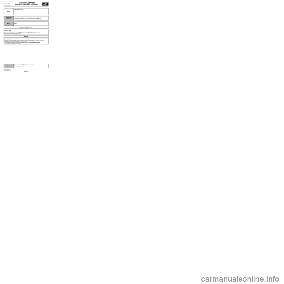
PR105
VEHICLE SPEED
PARAMETER
DEFINITIONThis parameter indicates the vehicle speed expressed in mph (km/h).
NOTESNone
Engine stopped, ignition on
PR105 = 0 km/h
If not correct, run fault finding on the ABS/ESP system (see 38C, Anti-lock braking system).
If the fault is still present, contact Techline.
Road test
Carry out a road test.
Check the consistency between the parameter value PR038 "Vehicle speed" in the domain of the ABS
computer and the speed displayed on the instrument panel.
If not correct, run fault finding on the ABS/ESP system (see 38C, Anti-lock braking system).
If the fault is still present, contact Techline.
AFTER REPAIRCarry out another fault finding check on the system.
Deal with any other faults.
Clear the stored faults.
BVRJH1_V04_PR105