engine RENAULT TWINGO 2009 2.G Transmission User Guide
[x] Cancel search | Manufacturer: RENAULT, Model Year: 2009, Model line: TWINGO, Model: RENAULT TWINGO 2009 2.GPages: 135
Page 17 of 135
21A-2
MANUAL GEARBOX
Manual gearbox oils: Draining - Filling
JB1 or JH3 or JR5
21A
DRAINING
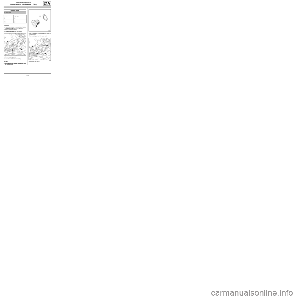
aPosition the vehicle on a two-post lift (see Vehicle:
Towing and lifting) (02A, Lifting equipment).
aRemove the engine undertray.
aFit a oil recovery tray under the gearbox.
aRemove the drain plug (1) .
aLet the oil run into the oil recovery tray.
FILLING
aparts always to be replaced: mechanism hous-
ing drain plug seal.aRefit a new seal on the drain plug with the groove (2)
facing the plug.
aRefit the drain plug fitted with its new seal.
aRemove the filler cap (3) . Equipment required
oil recovery tray
Gearbox Capacity (l)
JB1 3.4
JH3 2.8
JR5 2.3
18749
113764
18749
Page 18 of 135
21A-3
MANUAL GEARBOX
Manual gearbox oils: Draining - Filling
JB1 or JH3 or JR5
21A
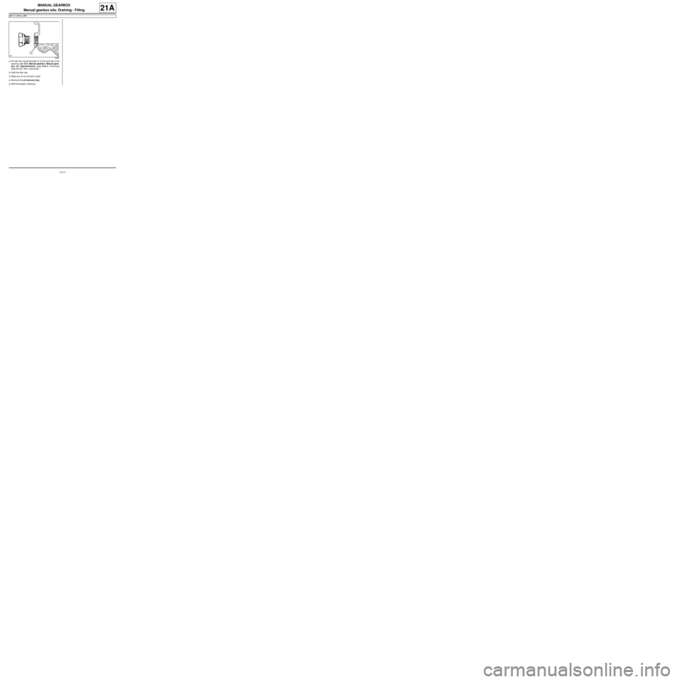
aFill with the recommended oil to the level (4) of the
opening (see 21A, Manual gearbox, Manual gear-
box oil: Specifications, page 21A-1) (Technical
Note 6012A, 04A, Lubricants).
aRefit the filler cap.
aWipe any oil run-off with a cloth.
aRemove the oil recovery tray.
aRefit the engine undertray.
92081
Page 27 of 135
21A-12
MANUAL GEARBOX
Manual gearbox: Identification
JH1 or JH3 or JR5
21A
K4J / K4M / K9K / D4F engines are fitted with type JH
and JR manual gearboxes.
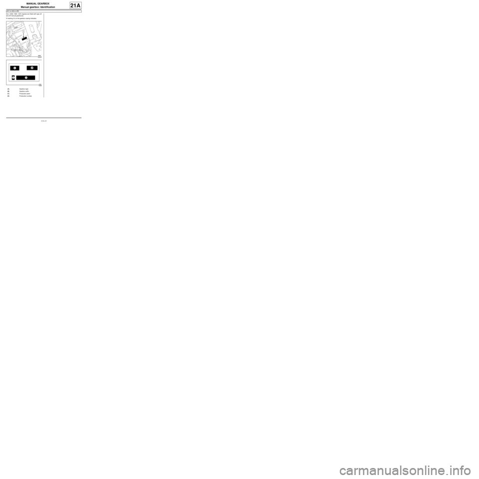
A marking (1) on the gearbox casing indicates:
109167
19860
(A) Gearbox type
(B) Gearbox suffi x
(C) Production plant
(D) Production number
Page 39 of 135
21A-24
MANUAL GEARBOX
Manual gearbox: Removal - Refitting
K9K, and JH3 or JR5
21A
REMOVAL
I - REMOVAL PREPARATION OPERATION
aPosition the vehicle on a two-post lift (see Vehicle:
Towing and lifting) (02A, Lifting equipment).
aRemove:
-the battery (see Battery: Removal - Refitting)
(80A, Battery),
-the battery tray (see Battery tray: Removal - Re-
fitting) (80A, Battery).
-the scuttle panel grille (see Scuttle panel grille:
Removal - Refitting) (56A, Exterior equipment),
-the scoop under the scuttle panel grille (see Scoop
under the scuttle panel grille: Removal - Refit-
ting) (56A, Exterior equipment).
aDisconnect the engine management computer con-
nectors.
aRemove:
-the engine management computer mounting bolts,
-the engine management computer mounting nuts.
aRemove the engine management computer mount-
ing.
aRemove the engine management computer wiring
harness nut from the engine management computer
mounting.
aRemove the engine management computer wiring
harness.
aRemove the engine management computer mount-
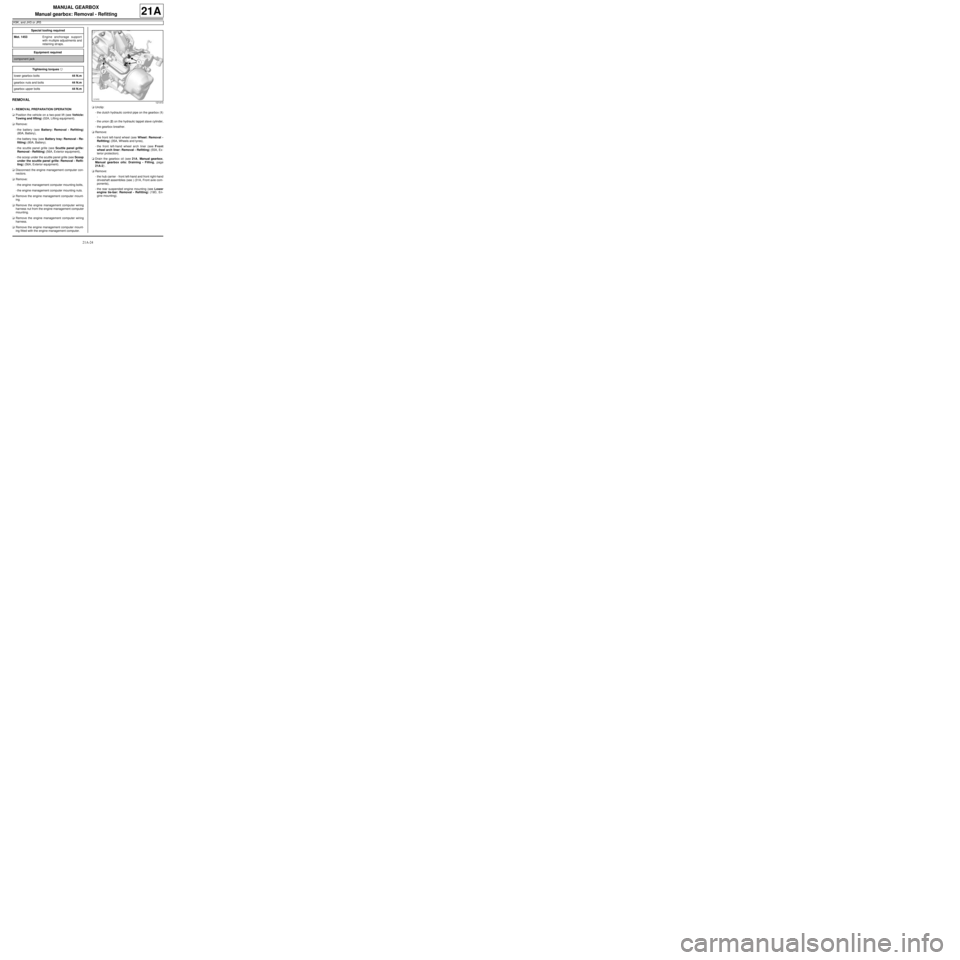
ing fitted with the engine management computer.aUnclip:
-the clutch hydraulic control pipe on the gearbox (1)
,
-the union (2) on the hydraulic tappet slave cylinder,
-the gearbox breather.
aRemove:
-the front left-hand wheel (see Wheel: Removal -
Refitting) (35A, Wheels and tyres),
-the front left-hand wheel arch liner (see Front
wheel arch liner: Removal - Refitting) (55A, Ex-
terior protection).
aDrain the gearbox oil (see 21A, Manual gearbox,
Manual gearbox oils: Draining - Filling, page
21A-2) .
aRemove:
-the hub carrier - front left-hand and front right-hand
driveshaft assemblies (see ) (31A, Front axle com-
ponents),
-the rear suspended engine mounting (see Lower
engine tie-bar: Removal - Refitting) (19D, En-
gine mounting). Special tooling required
Mot. 1453Engine anchorage support
with m ultiple adjustments and
retaining str aps.
Equipment required
component jack
Tightening torquesm
lower gearbox bolts44 N.m
gearbox nuts and bolts44 N.m
gearbox upper bolts44 N.m
121410
Page 40 of 135
21A-25
MANUAL GEARBOX
Manual gearbox: Removal - Refitting
K9K, and JH3 or JR5
21A
aLoosen the bolt (3) and the nut (4) on the upstream
strut of the catalytic converter on the gearbox.
aRemove:
-the bolt (5) from the upstream strut of the catalytic
converter on the catalytic converter,
-the upstream strut of the catalytic converter by slid-
ing it upwards,
-the starter (see Starter: Removal - Refitting)
(16A, Starting - Charging).
aFit the (Mot. 1453) :
-positioning it on the front wing opening stops and
on the headlight brackets,
-using the two engine lifting eyes to avoid the
« engine - gearbox » assembly tilting too much,
-making sure the tool is strapped to the vehicle.aRemove:
-the left-hand suspended engine mounting (see
Left-hand suspended engine mounting: Re-
moval - Refitting) (19D, Engine mounting),
-the subframe (see Front axle subframe: Removal
- Refitting) (31A, Front axle components).
II - OPERATION FOR REMOVAL OF PART
CONCERNED
aDetach the gearbox controls by pressing on the ca-
ble end pieces (6) .
aRemove the earth strap bolt.
aRemove the upper gearbox bell housing bolts.
aDisconnect:
-the speed and position sensor connector,
-the reverse gear switch connector.
aRemove:
-the lower gearbox bell housing bolts,
-the gearbox nuts,
-the gearbox studs.
aFit a component jack under the gearbox.
aRemove:
-the lower gearbox bell housing bolts,
-the gearbox.
106199
121415
108265
Page 41 of 135
21A-26
MANUAL GEARBOX
Manual gearbox: Removal - Refitting
K9K, and JH3 or JR5
21A
REFITTING
I - REFITTING OPERATION FOR PART
CONCERNED
aRefit:
-the gearbox using a component jack,
-the gearbox stud nuts,
-the gearbox lower bolts.
aTorque tighten:
-the lower gearbox bolts (44 N.m),
-the gearbox nuts and bolts (44 N.m).
aRefit the upper gearbox bolts.
aTorque tighten the gearbox upper bolts (44 N.m).
aRefit the earth strap bolt on the gearbox.
aConnect:
-the reverse gear switch connector,
-the speed and position sensor connector.
aClip the gearbox controls into place.
II - FINAL OPERATION
aRefit:
-the subframe (see Front axle subframe: Removal
- Refitting) (31A, Front axle components),
-the left-hand suspended engine mounting (see
Left-hand suspended engine mounting: Re-
moval - Refitting) (19D, Engine mounting).
aRemove the tool (Mot. 1453).
aRefit:
-the upstream strut of the catalytic converter by slid-
ing it upwards,
-the catalytic converter upstream strut bolt on the
catalytic converter.
aTighten the bolt and nut on the upstream strut of the
catalytic converter on the gearbox.
aRefit:
-the rear suspended engine mounting (see Lower
engine tie-bar: Removal - Refitting) (19D, En-
gine mounting),
-the hub carrier - front left-hand and front right-hand
driveshaft assemblies (see ) (31A, Front axle com-
ponents),
-the starter (see Starter: Removal - Refitting)
(16A, Starting - Charging),-the front left-hand wheel arch liner (see Front
wheel arch liner: Removal - Refitting) (55A, Ex-
terior protection),
-the front left-hand wheel (see Wheel: Removal -
Refitting) (35A, Wheels and tyres).
aClip:
-the union onto the hydraulic tappet slave cylinder,
-the hydraulic clutch control pipe,
-the gearbox breather.
aBleed the clutch (see Clutch circuit: Bleed) (37A,
Mechanical component controls).
aRefit the engine management computer mounting
fitted with the engine management computer.
aFit the engine management computer wiring har-
ness.
aRefit the engine management computer wiring har-
ness nut on the engine management computer
mounting.
aFit the engine management computer mounting.
aRefit:
-the engine management computer mounting bolts,
-the engine management computer mounting nuts.
aConnect the engine management computer connec-
tors.
aRefit:
-the scoop under the scuttle panel grille (see Scoop
under the scuttle panel grille: Removal - Refit-
ting) (56A, Exterior equipment),
-the scuttle panel grille (see Scuttle panel grille:
Removal - Refitting) (56A, Exterior equipment),
aFill up the gearbox oil (see 21A, Manual gearbox,
Manual gearbox oils: Draining - Filling, page
21A-2) .
aRefit:
-the battery tray (see Battery tray: Removal - Re-
fitting) (80A, Battery),
-the battery (see Battery: Removal - Refitting)
(80A, Battery).
Page 42 of 135
21A-27
MANUAL GEARBOX
Manual gearbox: Removal - Refitting
D4F, and JB1 – D7F, and JB1
21A
REMOVAL
I - REMOVAL PREPARATION OPERATION
aPosition the vehicle on a two-post lift (see Vehicle:
Towing and lifting) (MR 411, 02A, Lifting equip-
ment).
aRemove:
-the battery (see Battery: Removal - Refitting)
(MR 411, 80A, Battery),
-the battery tray (see Battery tray: Removal - Re-
fitting) (MR 411, 80A, Battery).
aRemove the air filter unit (see Air filter unit: Re-
moval - Refitting) (MR 411, 12A, Fuel mixture).
aRemove:
-the scuttle panel grille (see Scuttle panel grille:
Removal - Refitting) (MR 412, 56A, Exterior
equipment),
-the scoop under the scuttle panel grille (see Scoop
under the scuttle panel grille: Removal - Refit-
ting) (MR 412, 56A, Exterior equipment).aDisconnect the engine management computer con-
nectors.
aRemove:
-the engine management computer mounting bolts,
-the engine management computer mounting nuts.
aRemove the engine management computer mount-
ing.
aRemove the engine management computer wiring
harness nut from the engine management computer
mounting.
aRemove the engine management computer wiring
harness.
aRemove the engine management computer mount-
ing fitted with the engine management computer.
aUnclip:
-the clutch cable,
-the gearbox breather.
aRemove:
-the left-hand front wheel (see Wheel: Removal -
Refitting) (MR 411, 35A, Wheels and tyres),
-the front left-hand wheel arch liner (see Front
wheel arch liner: Removal - Refitting) (MR 412,
55A, Exterior protection).
aDrain the gearbox oil (see 21A, Manual gearbox,
Manual gearbox oils: Draining - Filling, page
21A-2) .
aRemove:
-the hub carrier - front left-hand and front right-hand
driveshaft assemblies (see ) (MR 411, 31A, Front
axle components),
-the rear suspended engine mounting (see Lower
engine tie-bar: Removal - Refitting) (MR 411,
19D, Engine mounting),
-the starter (see Starter: Removal - Refitting) (MR
411, 16A, Starting - Charging). Special tooling required
Mot. 1453Engine anchorage support
with m ultiple adjustments and
retaining str aps.
Equipment required
component jack
Tightening torquesm
gearbox mountings44 Nm
D4F
Page 43 of 135
21A-28
MANUAL GEARBOX
Manual gearbox: Removal - Refitting
D4F, and JB1 – D7F, and JB1
21A
aFit the (Mot. 1453) :
-positioning it on the front wing opening stops and
on the headlight brackets,
-using the two engine lifting eyes to avoid the
« engine - gearbox » assembly tilting too much,
-making sure the tool is strapped to the vehicle.
aRemove:
-the left-hand suspended engine mounting (see
Left-hand suspended engine mounting: Re-
moval - Refitting) (MR 411, 19D, Engine mount-
ing),
-the subframe (see Front axle subframe: Removal
- Refitting) (MR 411, 31A, Front axle component).
II - OPERATION FOR REMOVAL OF PART
CONCERNED
aDisconnect the reverse gear switch connector.
aRemove:
-the earth strap bolt on the gearbox,
-the gearbox upper bolts,
-the engine speed and position sensor (see Crank-
shaft position sensor: Removal - Refitting) (MR
411, 17B, Petrol injection).
-the gearbox lower bolts,
-the flywheel protection plate bolts,
-the flywheel protection plate,
-the gearbox stud nuts,
-the gearbox using a component jack.
REFITTING
I - REFITTING OPERATION FOR PART
CONCERNED
aRefit:
-the gearbox using a component jack.
-the gearbox mountings.
aTorque tighten the gearbox mountings (44 Nm).
aRefit:
-the engine speed and position sensor (see Crank-
shaft position sensor: Removal - Refitting) (MR
411, 17B, Petrol injection),
-the earth strap bolt on the gearbox.
aConnect the reverse gear switch connector.
II - FINAL OPERATION.
aRefit:
-the subframe (see Front axle subframe: Removal
- Refitting) (MR 411, 31A, Front axle compo-
nents),
-the left-hand suspended engine mounting (see
Left-hand suspended engine mounting: Re-
moval - Refitting) (MR 411, 19D, Engine mount-
ing).
aRemove the (Mot. 1453).
aRefit:
-the rear suspended engine mounting (see Lower
engine tie-bar: Removal - Refitting) (MR 411,
19D, Engine mounting),
-the hub carrier - front left-hand and front right-hand
driveshaft assemblies (see ) (MR 411, 31A, Front
axle components),
-the starter (see Starter: Removal - Refitting) (MR
411, 16A, Starting - Charging),
-the front left-hand wheel arch liner (see Front
wheel arch liner: Removal - Refitting) (MR 412,
55A, Exterior protection),
-the left-hand front wheel (see Wheel: Removal -
Refitting) (MR 411, 35A, Wheels and tyres).
aClip:
-the clutch cable,
-the gearbox breather.
121415
Page 44 of 135
21A-29
MANUAL GEARBOX
Manual gearbox: Removal - Refitting
D4F, and JB1 – D7F, and JB1
21A
aRefit the engine management computer mounting
fitted with the engine management computer.
aFit the engine management computer wiring har-
ness.
aRefit the engine management computer wiring har-
ness nut on the engine management computer
mounting.
aFit the engine management computer mounting.
aRefit:
-the engine management computer mounting bolts,
-the engine management computer mounting nuts.
aConnect the engine management computer connec-
tors.
aRefit:
-the scoop under the scuttle panel grille (see Scoop
under the scuttle panel grille: Removal - Refit-
ting) (MR 412, 56A, Exterior equipment),
-the scuttle panel grille (see Scuttle panel grille:
Removal - Refitting) (MR 412, 56A, Exterior
equipment).
aRefit the air filter box (see Air filter unit: Removal -
Refitting) (MR 411, 12A, Fuel mixture).
aFill up the gearbox oil (see 21A, Manual gearbox,
Manual gearbox oils: Draining - Filling, page
21A-2) .
aRefit:
-the battery tray (see Battery tray: Removal - Re-
fitting) (MR 411, 80A, Battery),
-the battery (see Battery: Removal - Refitting)
(MR 411, 80A, Battery). D4F
Page 45 of 135
21A-30
MANUAL GEARBOX
Manual gearbox: Removal - Refitting
K4M, and JR5
21A
REMOVAL
I - REMOVAL PREPARATION OPERATION
aPosition the vehicle on a two-post lift (see Vehicle:
Towing and lifting) (02A, Lifting equipment).
aRemove:
-the engine undertray,
-the battery (see Battery: Removal - Refitting)
(80A, Battery),
-the air filter unit (see Air filter unit: Removal - Re-
fitting) (12A, Fuel mixture),
-the petrol injection computer (see Petrol injection
computer: Removal - Refitting) (17B, Petrol in-
jection),
-the battery tray (see Battery tray: Removal - Re-
fitting) (80A, Battery),
-the front wheels (see Wheel: Removal - Refitting)
(35A, Wheels and tyres),
-the front wheel arch liners (see Front wheel arch
liner: Removal - Refitting) (55A, Exterior protec-
tion),
-the front bumper (see Front bumper: Removal -
Refitting) (55A, Exterior protection).
aDrain:
-the gearbox (see 21A, Manual gearbox, Manual
gearbox oils: Draining - Filling, page 21A-2) ,
-the engine cooling system (see Cooling system:
Draining - Refilling) (19A, Cooling),
-the refrigerant circuit (see Refrigerant circuit:
Draining - Filling) (62A, Air conditioning).aRemove:
-the rear suspended engine mounting (see Lower
engine tie-bar: Removal - Refitting) (19D, En-
gine mounting),
-the front axle subframe (see Front axle subframe:
Removal - Refitting) (31A, Front axle compo-
nents),
-the front left-hand driveshaft (see 29A, Drive-
shafts, Front left-hand driveshaft: Removal -
Refitting, page 29A-2) ,
-the front right-hand driveshaft (see 29A, Drive-
shafts, Front right-hand driveshaft: Removal -
Refitting, page 29A-8) ,
-the differential output seals (see 21A, Manual
gearbox, Differential output seal: Removal - Re-
fitting, page 21A-38) (21A, Manual gearbox),
-the engine - gearbox assembly (see Engine -
gearbox assembly: Removal - Refitting) (10A,
Engine and peripherals).
II - OPERATION FOR REMOVAL OF PART
CONCERNED
aRemove the “engine - gearbox” assembly from
theusing a workshop hoist.
aDisconnect the TDC sensor connector (1) . Equipment required
workshop hoist
Tightening torquesm
manual gearbox nuts
and bolts44 N.m
earth strap bolt on the
gearbox44 N.m
support bolts for the
suspended engine
mounting on the gear-
box62 N.m
132319