lock RENAULT TWINGO 2009 2.G Transmission User Guide
[x] Cancel search | Manufacturer: RENAULT, Model Year: 2009, Model line: TWINGO, Model: RENAULT TWINGO 2009 2.GPages: 135
Page 57 of 135

21A-42
MANUAL GEARBOX
Input shaft lip seal: Removal - Refitting
JB1
21A
aPlace the tightening clamp (3) onto the tube.
aLock the tightening clamp using the spanner (4) .
aTighten the nut firmly (5) .
aPosition the sleeve (6) and the split ring (7) .
aTurn the upper nut (8) .
aGently extract the guide tube.
REFITTING
I - REFITTING OPERATION FOR PART
CONCERNED
aPosition the new guide tube on the clutch housing.
aGently remove the guide tube with a press and the
(Bvi. 1828).
II - FINAL OPERATION.
aRefit the gearbox (see 21A, Manual gearbox, Man-
ual gearbox: Removal - Refitting, page 21A-24)
(MR 411, 21A, Manual gearbox).
aConnect the battery (see Battery: Removal - Refit-
ting) (MR 411, 80A, Battery).
98937
98938
98939
98935-1
Page 73 of 135
21B-13
SEQUENTIAL GEARBOX
Electro-hydraulic unit: Removal - Refitting
D4F, and JH1
21B
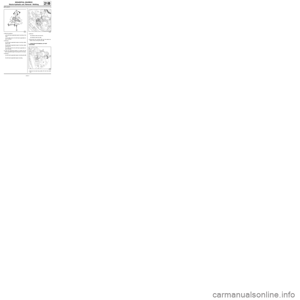
aMark the positions:
-of the left-hand suspended engine mounting on the
body,
-of the rubber pad on the left-hand suspended en-
gine mounting.
aRemove:
-the left-hand suspended engine mounting rubber
pad nut (4) ,
-the left-hand suspended engine mounting rubber
pad bolts (5) ,
-the rubber pad from the left-hand suspended en-
gine mounting
aLower the sequential gearbox to access the left-
hand suspended engine mounting bolt on the body.
aRemove:
-the left-hand suspended engine mounting bolts (6)
,
-the left-hand suspended engine mounting.aRemove:
-the selector shaft cover bolt (7) ,
-the selector shaft cover (8) .
aDisconnect the connector (9) from the electro-hy-
draulic unit by moving the lock (10) .
II - OPERATION FOR REMOVAL OF PART
CONCERNED
aRemove the clutch stay cable (11) from the clutch
fork.
120310122321
122168
Page 74 of 135
21B-14
SEQUENTIAL GEARBOX
Electro-hydraulic unit: Removal - Refitting
D4F, and JH1
21B
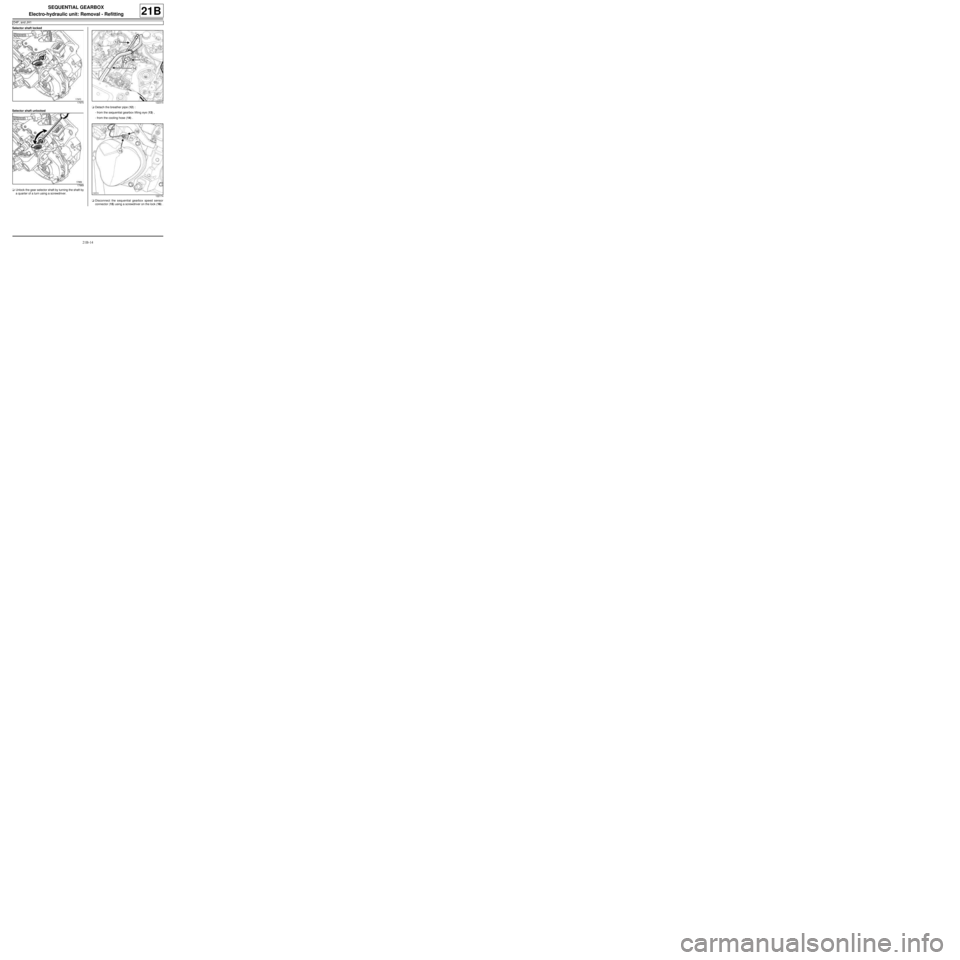
Selector shaft locked
Selector shaft unlocked
aUnlock the gear selector shaft by turning the shaft by
a quarter of a turn using a screwdriver.aDetach the breather pipe (12) :
-from the sequential gearbox lifting eye (13) ,
-from the cooling hose (14) .
aDisconnect the sequential gearbox speed sensor
connector (15) using a screwdriver on the lock (16) .
17970
17969122314
122174
Page 76 of 135
21B-16
SEQUENTIAL GEARBOX
Electro-hydraulic unit: Removal - Refitting
D4F, and JH1
21B
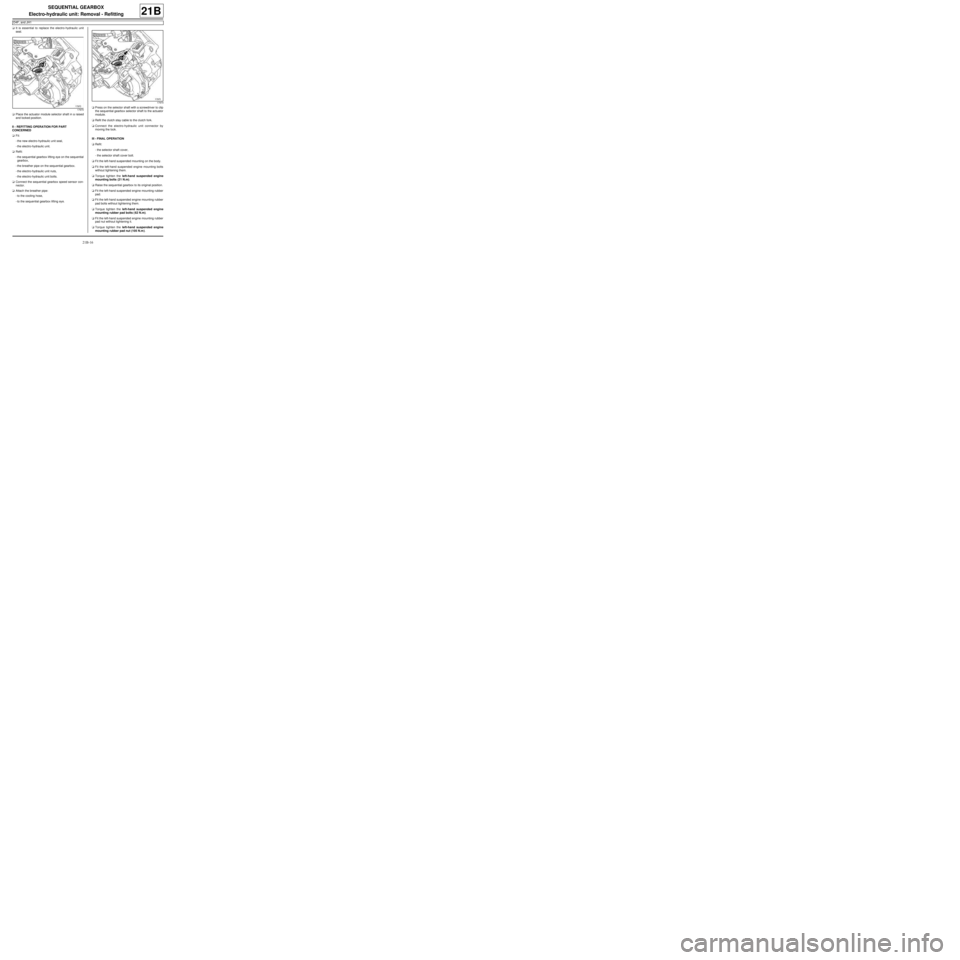
aIt is essential to replace the electro-hydraulic unit
seal.
aPlace the actuator module selector shaft in a raised
and locked position.
II - REFITTING OPERATION FOR PART
CONCERNED
aFit:
-the new electro-hydraulic unit seal,
-the electro-hydraulic unit.
aRefit:
-the sequential gearbox lifting eye on the sequential
gearbox,
-the breather pipe on the sequential gearbox.
-the electro-hydraulic unit nuts,
-the electro-hydraulic unit bolts.
aConnect the sequential gearbox speed sensor con-
nector.
aAttach the breather pipe:
-to the cooling hose,
-to the sequential gearbox lifting eye.aPress on the selector shaft with a screwdriver to clip
the sequential gearbox selector shaft to the actuator
module.
aRefit the clutch stay cable to the clutch fork.
aConnect the electro-hydraulic unit connector by
moving the lock.
III - FINAL OPERATION
aRefit:
-the selector shaft cover,
-the selector shaft cover bolt.
aFit the left-hand suspended mounting on the body.
aFit the left-hand suspended engine mounting bolts
without tightening them.
aTorque tighten the left-hand suspended engine
mounting bolts (21 N.m).
aRaise the sequential gearbox to its original position.
aFit the left-hand suspended engine mounting rubber
pad.
aFit the left-hand suspended engine mounting rubber
pad bolts without tightening them.
aTorque tighten the left-hand suspended engine
mounting rubber pad bolts ( 62 N.m).
aFit the left-hand suspended engine mounting rubber
pad nut without tightening it.
aTorque tighten the left-hand suspended engine
mounting rubber pad nut (105 N.m ).
17970
17970
Page 94 of 135
21B-34
SEQUENTIAL GEARBOX
Clutch position sensor: Removal - Refitting
D4F, and JH1
21B
REMOVAL
I - REMOVAL PREPARATION OPERATION
aPosition the vehicle on a two-post lift (see Vehicle:
Towing and lifting) (02A, Lifting equipment).
II - OPERATION FOR REMOVAL OF PART
CONCERNED
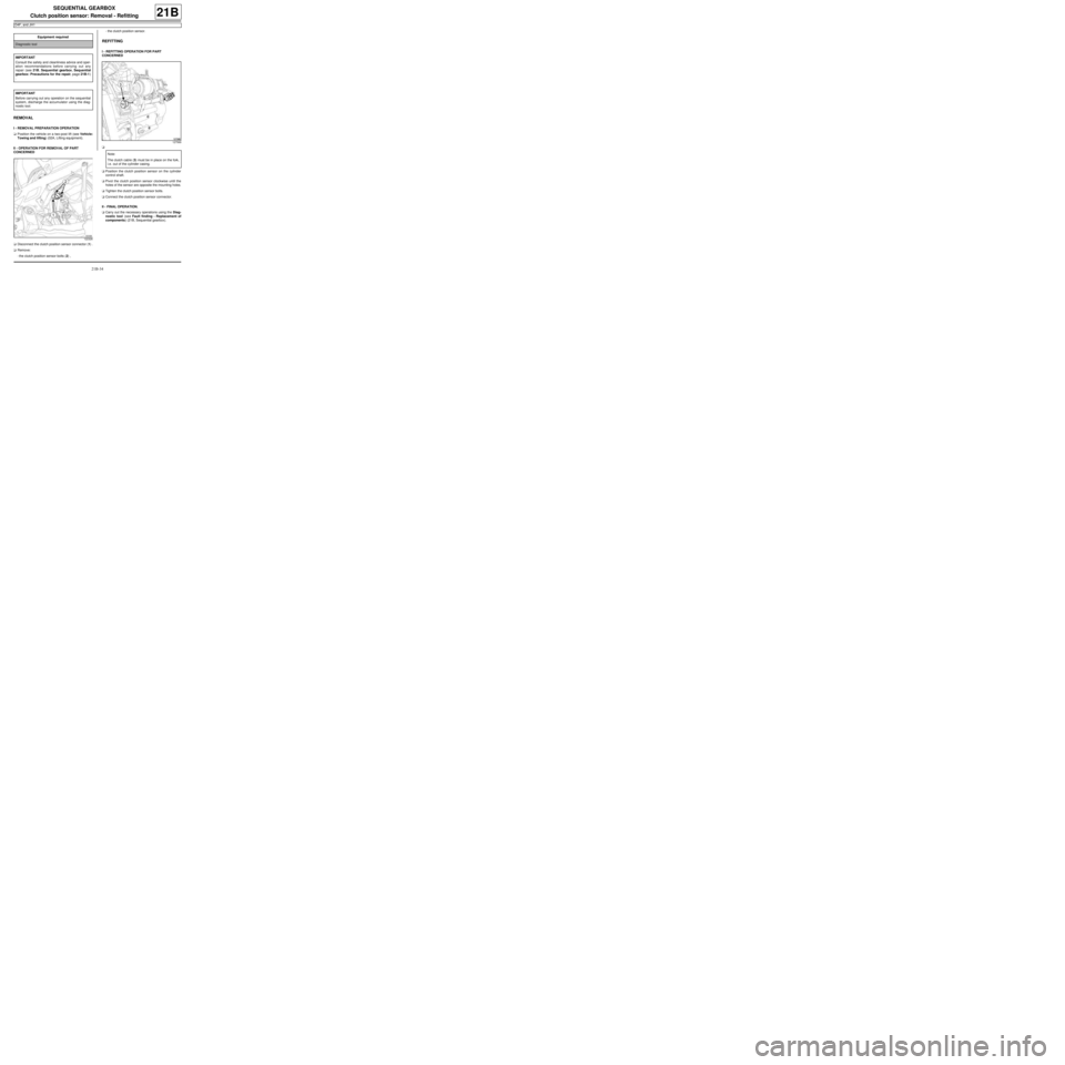
aDisconnect the clutch position sensor connector (1) .
aRemove:
-the clutch position sensor bolts (2) ,-the clutch position sensor.
REFITTING
I - REFITTING OPERATION FOR PART
CONCERNED
a
aPosition the clutch position sensor on the cylinder
control shaft.
aPivot the clutch position sensor clockwise until the
holes of the sensor are opposite the mounting holes.
aTighten the clutch position sensor bolts.
aConnect the clutch position sensor connector.
II - FINAL OPERATION.
aCarry out the necessary operations using the Diag-
nostic tool (see Fault finding - Replacement of
components) (21B, Sequential gearbox). Equipment required
Diagnostic tool
IMPORTANT
Consult the safety and cleanliness advice and oper-
ation recommendations before carrying out any
repair (see 21B, Sequential gearbox, Sequential
gearbox: Precautions for the repair, page 21B-1)
.
IMPORTANT
Before carrying out any operation on the sequential
system, discharge the accumulator using the diag-
nostic tool.
122326
127569
Note:
The clutch cab le (3) must be in place on the fork,
i.e. out of the cylinder casing.
Page 107 of 135
21B-47
SEQUENTIAL GEARBOX
Sequential gearbox converter: Removal - Refitting
D4F, and JH1
21B
REMOVAL
I - REMOVAL PREPARATION OPERATION
aRemove the battery (see Battery: Removal - Refit-
ting) (MR 411, 80A, Battery).
II - OPERATION FOR REMOVAL OF PART
CONCERNED
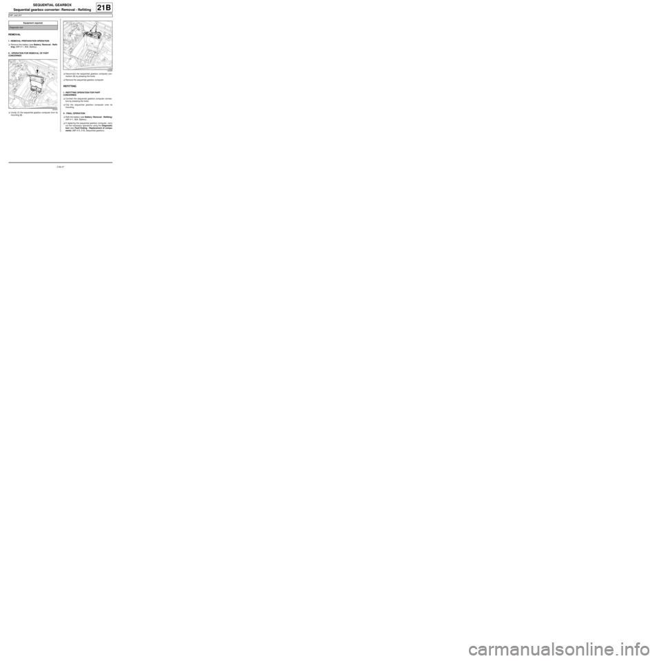
aUnclip (1) the sequential gearbox computer from its
mounting (2) .aDisconnect the sequential gearbox computer con-
nectors (3) by pressing the locks.
aRemove the sequential gearbox computer.
REFITTING
I - REFITTING OPERATION FOR PART
CONCERNED
aConnect the sequential gearbox computer connec-
tors by pressing the locks.
aClip the sequential gearbox computer onto its
mounting.
II - FINAL OPERATION
aRefit the battery (see Battery: Removal - Refitting)
(MR 411, 80A, Battery).
aIf replacing the sequential gearbox computer, carry
out the necessary operations using the Diagnostic
tool (see Fault finding - Replacement of compo-
nents) (MR 413, 21B, Sequential gearbox). Equipment required
Diagnostic tool
122324
122325
Page 109 of 135
29A-1
DRIVESHAFTS
Driveshaft: Precautions for the repair
JB1 or JH1 or JH3 or JR5
29A
WARNING
A gearbox oil leak at the driveshaft may destroy it.
WARNING
Lubricate the base of the bearing with MOLYKOTE
to prevent the bear ing sticking.
Make sure that the O-ring is correctly positioned in
the base of the relay bearing, if the bearing has
one.
WARNING
Always replace seals whenever the driveshaft is
removed.
WARNING
Always replace the left-hand driveshaft lock ring, if
the driveshaft has one.
WARNING
In order to prevent irreversible damage to the front
hub bear ing:
-Do not loosen or tighten the driveshaft nut when
the wheels are on the ground.
-Do not place the vehicle with its wheels on the
ground when the driveshaft has been loosened or
removed.
Page 110 of 135

29A-2
DRIVESHAFTS
Front left-hand driveshaft: Removal - Refitting
JB1 or JH1
29A
REMOVAL
I - REMOVAL PREPARATION OPERATION
aPosition the vehicle on a two-post lift (see Vehicle:
Towing and lifting) (02A, Lifting equipment).
aRemove:
-the engine undertray bolts,
-the engine undertray.
aDrain the manual gearbox (see 21A, Manual gear-
box, Manual gearbox oils: Draining - Filling, page
21A-2) .
aRemove the front left-hand wheel (see Wheel: Re-
moval - Refitting) (35A, Wheels and tyres).II - OPERATION FOR REMOVAL OF PART
CONCERNED
aDetach the wiring from the wheel speed sensor (1) .
aRemove:
-the hub nut (2) by immobilising the hub using the
tool (Rou. 604-01),
-the track rod end nut (3) ,
-the track rod end from the stub axle carrier using
the (Tav. 476),
-the shock absorber base bolts (4) . Special tooling required
Rou. 604-01Hub locking tool.
Tav. 476Ball joint extractor.
Tightening torquesm
the flange mounting
bolts21 Nm
shock absorber base
bolts105 N.m
track rod end nut37 Nm
hub nut280 N.m
WARNING
In order to prevent irreversible damage to the front
hub bear ing:
-Do not loosen or tighten the driveshaft nut when
the wheels are on the ground.
-Do not place the vehicle with its wheels on the
ground when the driveshaft has been loosened or
removed.
130488
Page 113 of 135
29A-5
DRIVESHAFTS
Front left-hand driveshaft: Removal - Refitting
JH3 or JR5
29A
REMOVAL
I - REMOVAL PREPARATION OPERATION
aPosition the vehicle on a two-post lift (see Vehicle:
Towing and lifting) (02A, Lifting equipment).
aRemove:
-the engine undertray.
-the front left-hand wheel (see Wheel: Removal -
Refitting) (35A, Wheels and tyres).
aDrain the gearbox (see 21A, Manual gearbox,
Manual gearbox oils: Draining - Filling, page
21A-2) .II - OPERATION FOR REMOVAL OF PART
CONCERNED
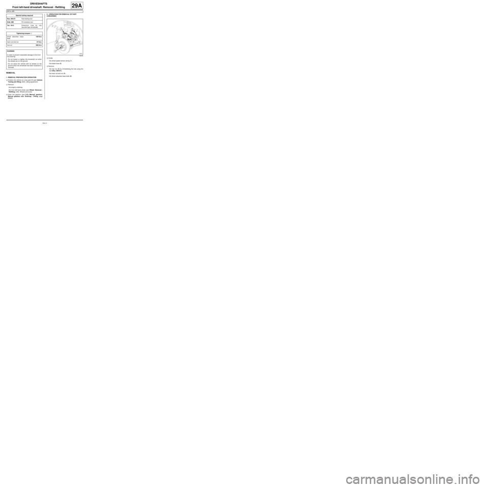
aUnclip:
-the wheel speed sensor wiring (1) ,
-the brake hose (2) .
aRemove:
-the hub nut (3) by immobilising the hub using the
tool (Rou. 604-01),
-the track rod end nut (4) ,
-the shock absorber base bolts (5) . Special tooling required
Rou. 604-01Hub locking tool.
Emb. 880Pin extractor tool.
Tav. 1813Extraction claw for clip
secured type driveshafts
Tightening torquesm
shock absorber base
bolts105 N.m
track rod end nut37 N.m
hub nut280 N.m
WARNING
In order to prevent irreversible damage to the front
hub bear ing:
-Do not loosen or tighten the driveshaft nut when
the wheels are on the ground.
-Do not place the vehicle with its wheels on the
ground when the driveshaft has been loosened or
removed.
132032
Page 116 of 135
29A-8
DRIVESHAFTS
Front right-hand driveshaft: Removal - Refitting
JB1 or JH1
29A
REMOVAL
I - REMOVAL PREPARATION OPERATION
aPosition the vehicle on a two-post lift (see Vehicle:
Towing and lifting) (02A, Lifting equipment).
aRemove:
-the engine undertray bolts,
-the engine undertray,
-the front right-hand wheel (see Wheel: Removal -
Refitting) (35A, Wheels and tyres).II - OPERATION FOR REMOVAL OF PART
CONCERNED
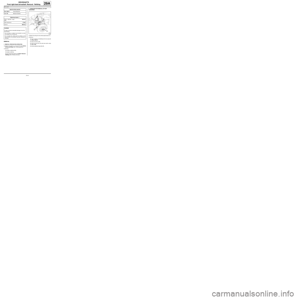
aDetach the wiring from the wheel speed sensor (1) .
aRemove:
-the hub nut (2) by immobilising the hub using the
tool (Rou. 604-01),
-the track rod end nut (3) ,
-the track rod end from the stub axle carrier using
the (Tav. 476),
-the shock absorber base bolts (4) . Special tooling required
Rou. 604-01Hub locking tool.
Tav. 476Ball joint extractor.
Tightening torquesm
shock absorber base
bolts105 N.m
track rod end nut37 Nm
hub nut280 N.m
WARNING
In order to prevent irreversible damage to the front
hub bear ing:
-Do not loosen or tighten the driveshaft nut when
the wheels are on the ground.
-Do not place the vehicle with its wheels on the
ground when the driveshaft has been loosened or
removed.
130490