lock RENAULT TWINGO 2009 2.G Transmission Owner's Manual
[x] Cancel search | Manufacturer: RENAULT, Model Year: 2009, Model line: TWINGO, Model: RENAULT TWINGO 2009 2.GPages: 135
Page 118 of 135
29A-10
DRIVESHAFTS
Front right-hand driveshaft: Removal - Refitting
JH3 or JR5
29A
REMOVAL
I - REMOVAL PREPARATION OPERATION
aPosition the vehicle on a two-post lift (see Vehicle:
Towing and lifting) (02A, Lifting equipment).
aRemove:
-the engine undertray,
-the front right-hand wheel (see Wheel: Removal -
Refitting) (35A, Wheels and tyres).
aDrain the gearbox (see 21A, Manual gearbox,
Manual gearbox oils: Draining - Filling, page
21A-2) .II - OPERATION FOR REMOVAL OF PART
CONCERNED
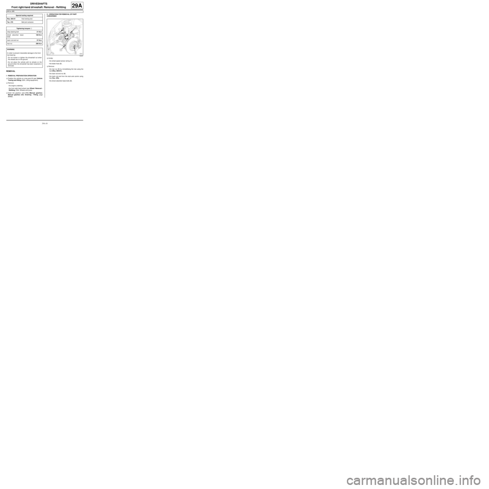
aUnclip:
-the wheel speed sensor wiring (1) ,
-the brake hose (2) .
aRemove:
-the hub nut (3) by immobilising the hub using the
tool (Rou. 604-01),
-the track rod end nut (4) ,
-the track rod end from the stub axle carrier using
the (Tav. 476),
-the shock absorber base bolts (5) . Special tooling required
Rou. 604-01Hub locking tool.
Tav. 476Ball joint extractor.
Tightening torquesm
relay bearing bolt21 N.m
shock absorber base
bolts105 N.m
track rod end nut37 N.m
hub nut280 N.m
WARNING
In order to prevent irreversible damage to the front
hub bear ing:
-Do not loosen or tighten the driveshaft nut when
the wheels are on the ground.
-Do not place the vehicle with its wheels on the
ground when the driveshaft has been loosened or
removed.
132027
Page 122 of 135
29A-14
DRIVESHAFTS
Front driveshaft gaiter, wheel side: Removal - Refitting
JB1 or JH1 or JH3 or JR5
29A
REMOVAL
I - REMOVAL PREPARATION OPERATION
aPosition the vehicle on a two-post lift (see Vehicle:
Towing and lifting) (02A, Lifting equipment).
aRemove:
-the engine undertray,
-the wheel on the side concerned (see Wheel: Re-
moval - Refitting) (35A, Wheels and tyres),
-the driveshaft on the side concerned (see 29A,
Driveshafts, Front right-hand driveshaft: Re-
moval - Refitting, page 29A-8) or (see 29A,
Driveshafts, Front left-hand driveshaft: Remov-
al - Refitting, page 29A-2) . Special tooling required
Tav. 1168"Clic" type clip pliers for drive-
shafts with a thermoplastic
gaiter.
Tav. 1784Pliers for the driveshaft gaiter
collar.
Equipment required
steel inertia hammer
roll pin punch
par ts washer
109634
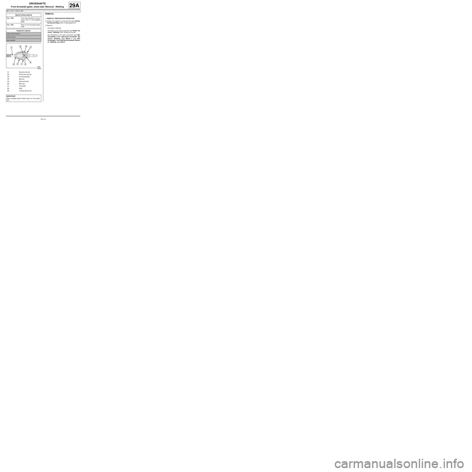
(1) Big securing clip
(2) Small secur ing clip
(3) Driveshaft gaiter
(4) Ball hub
(5) Stub axle bowl
(6) Ball race
(7) Driveshaft
(8) Balls
(9) Locking spring r ing
IMPORTANT
Wear leaktight gloves (Nitrile type) for this opera-
tion.
Page 123 of 135
29A-15
DRIVESHAFTS
Front driveshaft gaiter, wheel side: Removal - Refitting
JB1 or JH1 or JH3 or JR5
29A
II - OPERATION FOR REMOVAL OF PART
CONCERNED
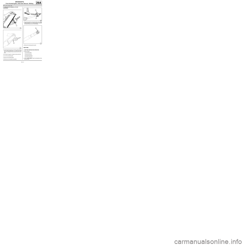
aCut the big securing clip (1) and the small securing
clip (2) using cutting pliers or a metal saw, taking
care not to damage the stub axle bowl and the drive-
shaft.
aPush back the gaiter to release the stub axle bowl.
aCut off the driveshaft gaiter.
aRemove the driveshaft gaiter.
aRemove as much grease as possible.aTap the hub bearing several times (3) using a steel
inertia hammer and a roll pin punch to separate
the stub axle bowl (4) from the driveshaft.
aRemove the locking spring ring (5) .
REFITTING
I - REFITTING PREPARATION OPERATION
aAlways replace:
-the driveshaft gaiter,
-the big securing clip,
-the small securing clip,
-the locking spring ring.
aUsing a parts washer, clean the driveshaft and the
stub axle bowl.
93034
128415
128077
128411
Page 124 of 135
29A-16
DRIVESHAFTS
Front driveshaft gaiter, wheel side: Removal - Refitting
JB1 or JH1 or JH3 or JR5
29A
II - REFITTING OPERATION FOR PART
CONCERNED
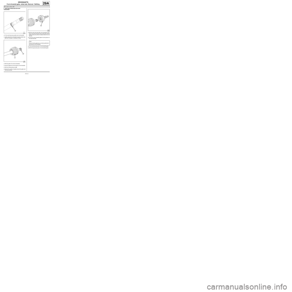
aFit the small securing clip (6) onto the driveshaft.
aLightly lubricate the driveshaft using the grease sup-
plied with the gaiter to facilitate its fitting.
aRefit the gaiter (7) onto the driveshaft.
aInsert the gaiter lip into the groove of the driveshaft.
aRefit the locking spring ring (8) .
aSpread the quantity of grease around the gaiter and
the stub axle bowl.aRefit the stub axle bowl (9) to the driveshaft by tap-
ping on the stub axle bowl using a brass drift until the
locking spring ring clicks into place behind the hub
bearing.
aFit the lip of the driveshaft gaiter into the groove on
the stub axle bowl.
aFit the small securing clip on the driveshaft gaiter.
aRefit the big securing clip on the driveshaft gaiter.
128412
128416
109768
Note:
Chec k that the gaiter lip is correctly positioned in
the g roove of the driveshaft.
Page 128 of 135
29A-20
DRIVESHAFTS
Front right-hand driveshaft gaiter, gearbox side: Removal - Refitting
JB1 or JH1 or JH3 or JR5
29A
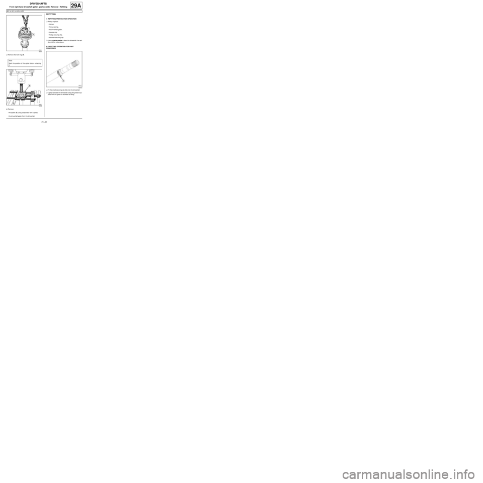
aRemove the lock ring (4) .
aRemove:
-the spider (5) using a separator and a press,
-the driveshaft gaiter from the driveshaft.
REFITTING
I - REFITTING PREPARATION OPERATION
aAlways replace:
-the cup,
-the cup spring,
-the driveshaft gaiter,
-the stop ring,
-the big securing clip,
-the small securing clip.
aUsing a parts washer, clean the driveshaft, the spi-
der and the yoke sleeve.
II - REFITTING OPERATION FOR PART
CONCERNED
aFit the small securing clip (6) onto the driveshaft.
aLightly lubricate the driveshaft using the grease sup-
plied with the gaiter to facilitate its fitting.
90387
Note:
Mark the position of the spider before extracting
it.
90388
128412
Page 131 of 135
29A-23
DRIVESHAFTS
Front left-hand driveshaft gaiter, gearbox side: Removal - Refitting
JH3 or JR5
29A
REMOVAL
I - REMOVAL PREPARATION OPERATION
aRemove the front left-hand driveshaft (see 29A,
Driveshafts, Front left-hand driveshaft: Removal
- Refitting, page 29A-2) .
II - REMOVAL OPERATION
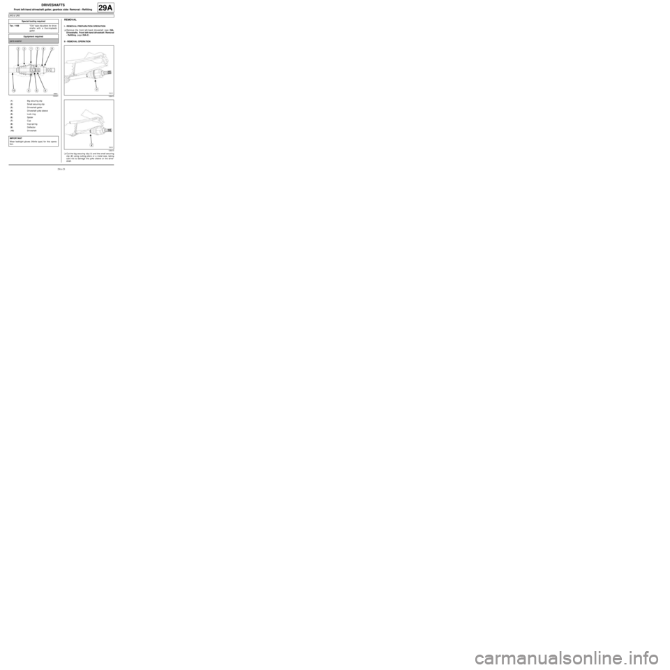
aCut the big securing clip (1) and the small securing
clip (2) using cutting pliers or a metal saw, taking
care not to damage the yoke sleeve or the drive-
shaft. Special tooling required
Tav. 1168"Clic" type clip pliers for drive-
shafts with a thermoplastic
gaiter.
Equipment required
par ts washer
109401
(1) Big securing clip
(2) Small secur ing clip
(3) Driveshaft gaiter
(4) Driveshaft yoke sleeve
(5) Lock r ing
(6) Spider
(7) Cup
(8) Cup spr ing
(9) Deflector
(10) Driveshaft
IMPORTANT
Wear leaktight gloves (Nitrile type) for this opera-
tion.
128413
128414
Page 132 of 135
29A-24
DRIVESHAFTS
Front left-hand driveshaft gaiter, gearbox side: Removal - Refitting
JH3 or JR5
29A
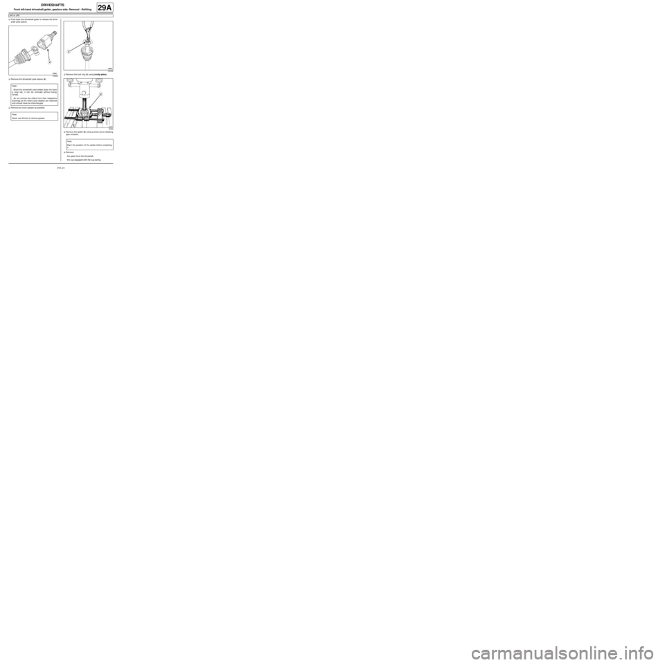
aPush back the driveshaft gaiter to release the drive-
shaft yoke sleeve.
aRemove the driveshaft yoke sleeve (4) .
aRemove as much grease as possible.aRemove the lock ring (5) using circlip pliers.
aRemove the spider (6) using a press and a releasing
type extractor.
aRemove:
-the gaiter from the driveshaft,
-the cup equipped with the cup spring.
109408
Note:
- Since the driveshaft yoke sleeve does not have
a stop tab, it can be removed without being
forced,
- do not remove the rollers from their respective
bushings as the rollers and needles are matched
and should never be interchanged.
Note:
Never use thinner to remove grease.
109409
90388
Note:
Mar k the position of the spider before extracting
it.
Page 133 of 135
29A-25
DRIVESHAFTS
Front left-hand driveshaft gaiter, gearbox side: Removal - Refitting
JH3 or JR5
29A
REFITTING
I - REFITTING PREPARATION OPERATION
aparts always to be replaced: Front left-hand
driveshaft gaiter, gearbox side.
aparts always to be replaced: gearbox side front
driveshaft seal locking ring.
aAlways replace:
-the cup,
-the cup spring,
-the big securing clip,
-the small securing clip.
aUse a parts washer to clean the driveshaft, the spi-
der and the driveshaft yoke sleeve.
II - REFITTING OPERATION
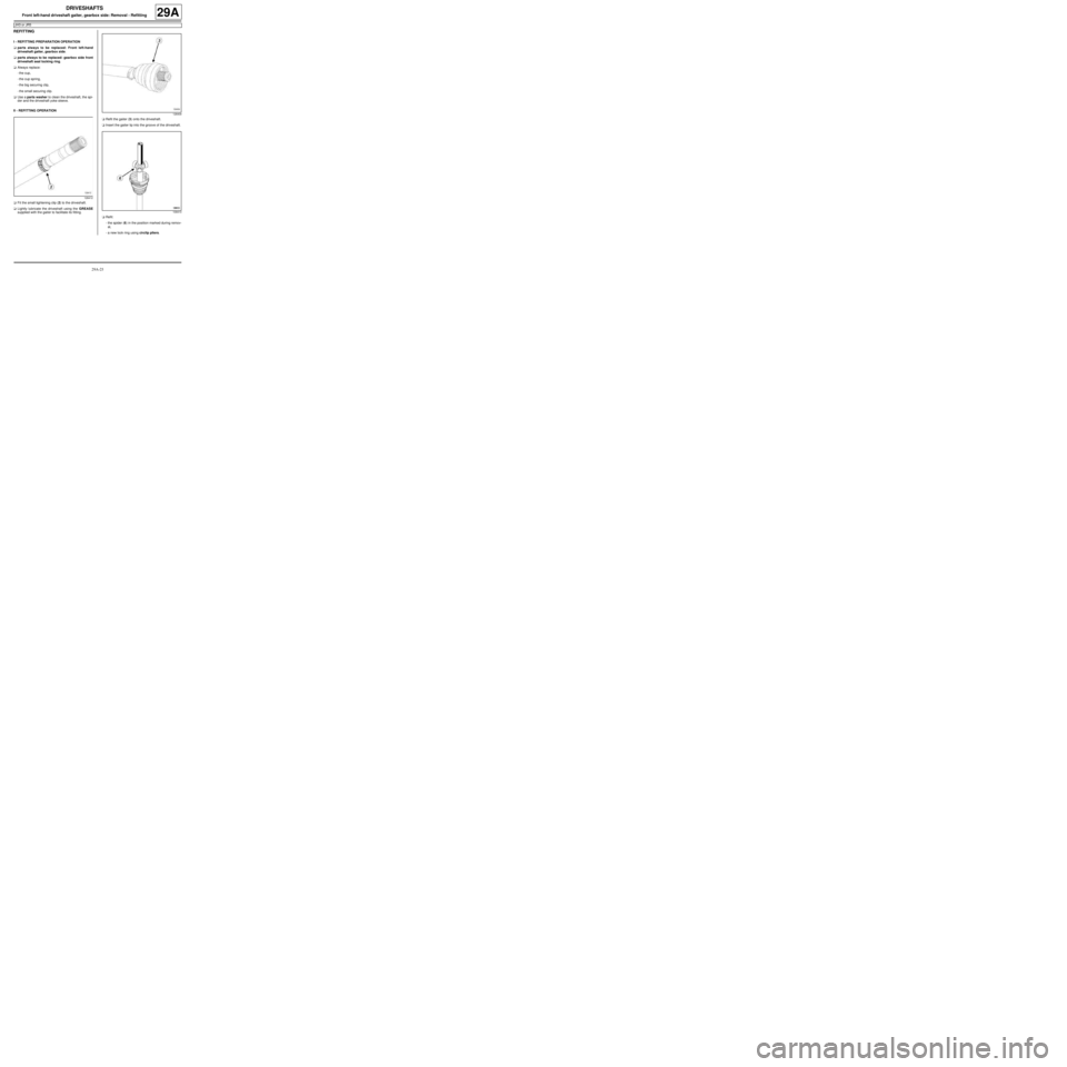
aFit the small tightening clip (2) to the driveshaft.
aLightly lubricate the driveshaft using the GREASE
supplied with the gaiter to facilitate its fitting.aRefit the gaiter (3) onto the driveshaft.
aInsert the gaiter lip into the groove of the driveshaft.
aRefit:
-the spider (6) in the position marked during remov-
al,
-a new lock ring using circlip pliers.
128412
128409
109410