ignition RENAULT TWINGO 2009 2.G Transmission Workshop Manual
[x] Cancel search | Manufacturer: RENAULT, Model Year: 2009, Model line: TWINGO, Model: RENAULT TWINGO 2009 2.GPages: 135
Page 61 of 135
21B-1
SEQUENTIAL GEARBOX
Sequential gearbox: Precautions for the repair
D4F, and JH1
21B
I - SEQUENTIAL GEARBOX
II - SEQUENTIAL GEARBOX COMPUTER
To disconnect the computer, switch off the ignition and
wait for 1 minute.
III - ELECTRO-HYDRAULIC UNIT
Discharge the pressure accumulator using the Diag-
nostic tool before any operation on the electro-hy-
draulic unit.
Be careful not to twist the high pressure pipes when re-
moving the electro-hydraulic unit.
IV - GEAR SELECTION SENSOREquipment required
Diagnostic tool
IMPORTANT
Before any operation on the sequential system, dis-
charge the accumulator using the Diagnostic tool.
WARNING
If any operation is carried out on the electro-hydrau-
lic unit, it is essential to clean the unit using a clean-
ing product and compressed air.
Never leave the circuit open and never use a high
pressure cleaner.
WARNING
After the accumulator has been fully filled (15 sec-
onds after the ignition has been switched on): the
oil level is at the MINIMUM mark.
WARNING
To remove the gear selection sensor it is essential
that you shift to first gear before removal.
Page 67 of 135
21B-7
SEQUENTIAL GEARBOX
Pressure accumulator: Removal - Refitting
D4F, and JH1
21B
II - OPERATION FOR REMOVAL OF PART
CONCERNED
a
aRemove the pressure accumulator (8) from the actu-
ator module using the (Mot. 445) (9) .
REFITTING
I - REFITTING PREPARATION OPERATION
aIf replacing the pressure accumulator, affix a safety
label to the accumulator.
aIt is essential to replace the pressure accumulator
seal.
II - REFITTING OPERATION FOR PART
CONCERNED
aRefit the pressure accumulator onto the actuator
module using the (Mot. 445).
III - FINAL OPERATION
aClip the pump assembly supply connector onto the
electro-hydraulic unit connector mounting.
aConnect the pump assembly supply connector.aRefit:
-the sequential gearbox lifting eye on the sequential
gearbox,
-the sequential gearbox lifting eye nut,
-the breather pipe on the sequential gearbox.
aAttach the breather pipe:
-to the cooling hose,
-to the sequential gearbox lifting eye.
aFit:
-the petrol injection computer support,
-the engine wiring harness on the petrol injection
computer mounting.
aRefit:
-the petrol injection computer mounting bolts,
-the engine wiring harness nut on the petrol injec-
tion computer mounting,
-the petrol injection computer mounting nut.
aClip onto the petrol injection computer mounting:
-the battery wiring harness,
-the petrol injection computer wiring harness,
-the sequential gearbox computer wiring harness,
-the cooling hose.
aRefit:
-the petrol injection computer (see Petrol injection
computer: Removal - Refitting) (MR 411, 17B,
Petrol injection),
-the battery tray (see Battery tray: Removal - Re-
fitting) (MR 411, 80A, Battery),
-the sequential gearbox computer (see 21B, Se-
quential gearbox, Sequential gearbox convert-
er: Removal - Refitting, page 21B-47) ,
-the battery (see Battery: Removal - Refitting)
(MR 411, 80A, Battery).
aFill the electric pump assembly reservoir with oil
(see Sequential gearbox oil: Specifications)
(Technical Note 6012, 04A, Lubricants) to between
32 and 38 mm above the MIN mark.
122315
Note:
Prepare for oil to flow out of the electro-hydraulic
unit.
WARNING
After the accumulator has been fully filled (15
seconds after the ignition has been switched on):
the oil level is at the MINIMUM mark.
Page 70 of 135
21B-10
SEQUENTIAL GEARBOX
Pump assembly reservoir: Removal - Refitting
D4F, and JH1
21B
REFITTING
I - REFITTING PREPARATION OPERATION
aIn the event of replacement, refit:
-the low pressure hose,
-the low pressure hose clip.
aIt is essential to replace the pump assembly reser-
voir seal on the pump inlet.
II - REFITTING OPERATION FOR PART
CONCERNED
aRefit:
-the pump assembly reservoir,
-the pump assembly reservoir bolts.
III - FINAL OPERATION
aAssemble:
-the electro-hydraulic unit (see 21B, Sequential
gearbox, Electro-hydraulic unit: Removal - Re-
fitting, page 21B-11) ,
aRemove
-the pump assembly on the electro-hydraulic unit
(see 21B, Sequential gearbox, Pump assembly:
Removal - Refitting, page 21B-18) ,
-the front left-hand wheel arch liner (see Front
wheel arch liner: Removal - Refitting) (MR 412,
55A, Exterior protection),
-the left-hand front wheel (see Wheel: Removal -
Refitting) (MR 411, 35A, Wheels and tyres),
-the rear suspended engine mounting (see Lower
engine tie-bar: Removal - Refitting) (MR 411,
19D, Engine mounting),
-the petrol injection computer (see Petrol injection
computer: Removal - Refitting) (MR 411, 17B,
Petrol injection),
-the battery tray (see Battery tray: Removal - Re-
fitting) (MR 411, 80A, Battery),
-the sequential gearbox computer (see 21B, Se-
quential gearbox, Sequential gearbox convert-
er: Removal - Refitting, page 21B-47) ,
-the battery (see Battery: Removal - Refitting)
(MR 411, 80A, Battery).aFill the electric pump assembly reservoir with oil
(see Sequential gearbox oil: Specifications)
(Technical Note 6012, 04A, Lubricants) to between
32 and 38 mm above the MIN mark.
aCarry out the necessary operations using the Diag-
nostic tool (see Fault finding - Replacement of
components) (MR 413, 21B, Sequential gearbox). WARNING
After the accumulator has been fully filled (15
seconds after the ignition has been switched on):
the oil level is at the MINIMUM mark.
Page 77 of 135

21B-17
SEQUENTIAL GEARBOX
Electro-hydraulic unit: Removal - Refitting
D4F, and JH1
21B
aRefit:
-the front left-hand wheel arch liner (see Front
wheel arch liner: Removal - Refitting) (MR 412,
55A, Exterior protection),
-the left-hand front wheel (see Wheel: Removal -
Refitting) (MR 411, 35A, Wheels and tyres),
-the rear suspended engine mounting (see Lower
engine tie-bar: Removal - Refitting) (MR 411,
19D, Engine mounting).
Refit.
aFit:
-the petrol injection computer support,
-the engine wiring harness on the petrol injection
computer mounting.
aRefit:
-the petrol injection computer mounting bolts,
-the engine wiring harness nut on the petrol injec-
tion computer mounting,
-the petrol injection computer mounting nut.
aClip onto the petrol injection computer mounting:
-the battery wiring harness,
-the petrol injection computer wiring harness,
-the sequential gearbox computer wiring harness,
-the cooling hose.
aRefit:
-the petrol injection computer (see Petrol injection
computer: Removal - Refitting) (MR 411, 17B,
Petrol injection),
-the battery tray (see Battery tray: Removal - Re-
fitting) (MR 411, 80A, Battery),
-the sequential gearbox computer (see 21B, Se-
quential gearbox, Sequential gearbox convert-
er: Removal - Refitting, page 21B-47) ,
-the battery (see Battery: Removal - Refitting)
(MR 411, 80A, Battery).
aFill the electric pump assembly reservoir with oil
(see Sequential gearbox oil: Specifications)
(Technical Note 6012, 04A, Lubricants) to between
32 and 38 mm above the MIN mark.aIf replacing the electro-hydraulic unit, carry out the
necessary operations using the Diagnostic tool
(see Fault finding - Replacement of components)
(MR 413, 21B, Sequential gearbox).
WARNING
After the accumulator has been fully filled (15
seconds after the ignition has been switched on):
the oil level is at the MINIMUM mark.
Page 79 of 135
21B-19
SEQUENTIAL GEARBOX
Pump assembly: Removal - Refitting
D4F, and JH1
21B
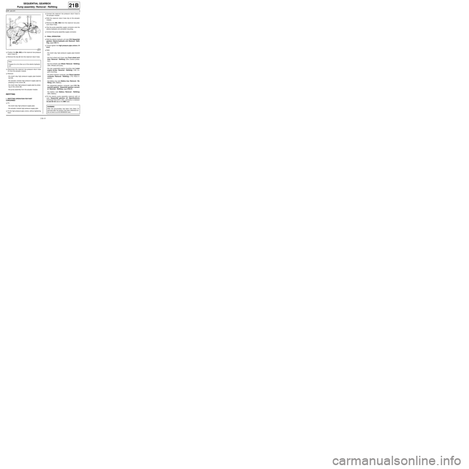
aPosition the (Ms. 583) on the reservoir low pressure
return hose (1) .
aRemove the clip (2) from the reservoir return hose.
aDisconnect the reservoir low pressure return hose
(1) from the actuator module.
aRemove:
-the clutch stay high pressure supply pipe bracket
bolt (3) ,
-the actuator module high pressure supply pipe by
pressing on the unions (4) ,
-the clutch stay high pressure supply pipe by press-
ing on the unions (5) ,
-the pump assembly from the actuator module.
REFITTING
I - REFITTING OPERATION FOR PART
CONCERNED
aFit:
-the clutch stay high pressure supply pipe,
-the actuator module high pressure supply pipe.
aFit the high pressure pipe unions, without tightening
them.aConnect the reservoir low pressure return hose to
the actuator module.
aRefit the reservoir return hose clip on the actuator
module.
aRemove the (Ms. 583) from the reservoir low pres-
sure return hose.
aClip the pump assembly supply connector onto the
electro-hydraulic unit connector mounting.
aConnect the pump assembly supply connector.
II - FINAL OPERATION
aRefit the electro-hydraulic unit (see 21B, Sequential
gearbox, Electro-hydraulic unit: Removal - Refit-
ting, page 21B-11) .
aTorque tighten the high pressure pipe unions (14
N.m).
aRefit:
-the clutch stay high pressure supply pipe bracket
bolt,
-the front wheel arch liners (see Front wheel arch
liner: Removal - Refitting) (55A, Exterior protec-
tion),
-the front wheels (see Wheel: Removal - Refitting)
(35A, Wheels and tyres),
-the rear suspended engine mounting (see Lower
engine tie-bar: Removal - Refitting) (19D, En-
gine mounting),
-the petrol injection computer (see Petrol injection
computer: Removal - Refitting) (17B, Petrol in-
jection),
-the battery tray (see Battery tray: Removal - Re-
fitting) (80A, Battery),
-the sequential gearbox computer (see 21B, Se-
quential gearbox, Sequential gearbox convert-
er: Removal - Refitting, page 21B-47) ,
-the battery (see Battery: Removal - Refitting)
(80A, Battery).
aFill the electric pump assembly reservoir with oil
(see Sequential gearbox oil: Specifications)
(Technical Note 6012, 04A, Lubricants) to between
32 and 38 mm above the MIN mark.
122171
Note:
Prepare for oil to flow out of the electro-hydraulic
unit.
WARNING
After the accumulator has been fully filled (15
seconds after the ignition has been switched on):
the oil level is at the MINIMUM mark.
Page 86 of 135

21B-26
SEQUENTIAL GEARBOX
Solenoid valves: Removal - Refitting
D4F, and JH1
21B
aFit the left-hand suspended engine mounting rubber
pad nut without tightening it.
aTorque tighten the left-hand suspended engine
mounting rubber pad nut (105 N.m ).
aRefit:
-the rear suspended engine mounting (see Lower
engine tie-bar: Removal - Refitting) (MR 411,
19D, Engine mounting),
-the front left-hand wheel arch liner (see Front
wheel arch liner: Removal - Refitting) (MR 412,
55A, Exterior protection),
-the left-hand front wheel (see Wheel: Removal -
Refitting) (MR 411, 35A, Wheels and tyres).
3 - Refitting all solenoid valves
aFit:
-the petrol injection computer support,
-the engine wiring harness on the petrol injection
computer mounting.
aRefit:
-the petrol injection computer mounting bolts,
-the engine wiring harness nut on the petrol injec-
tion computer mounting,
-the petrol injection computer mounting nut.
aClip onto the petrol injection computer mounting:
-the battery wiring harness,
-the petrol injection computer wiring harness,
-the sequential gearbox computer wiring harness,
-the cooling hose.
aRefit:
-the petrol injection computer (see Petrol injection
computer: Removal - Refitting) (MR 411, 17B,
Petrol injection),
-the battery tray (see Battery tray: Removal - Re-
fitting) (MR 411, 80A, Battery),
-the sequential gearbox computer (see 21B, Se-
quential gearbox, Sequential gearbox convert-
er: Removal - Refitting, page 21B-47) ,
-the battery (see Battery: Removal - Refitting)
(MR 411, 80A, Battery).aFill the electric pump assembly reservoir with oil
(see Sequential gearbox oil: Specifications)
(Technical Note 6012, 04A, Lubricants) to between
32 and 38 mm above the MIN mark.
aCarry out the necessary operations using the Diag-
nostic tool (see Fault finding - Replacement of
components) (MR 413, 21B, Sequential gearbox). WARNING
After the accumulator has been fully filled (15
seconds after the ignition has been switched on):
the oil level is at the MINIMUM mark.
Page 90 of 135
21B-30
SEQUENTIAL GEARBOX
Actuator module: Removal - Refitting
D4F, and JH1
21B
-the sequential gearbox computer (see 21B, Se-
quential gearbox, Sequential gearbox convert-
er: Removal - Refitting, page 21B-47) ,
-the battery (see Battery: Removal - Refitting)
(MR 411, 80A, Battery),
aFill the electric pump assembly reservoir with oil
(see Sequential gearbox oil: Specifications)
(Technical Note 6012, 04A, Lubricants) to between
32 and 38 mm above the MIN mark.
aCarry out the necessary operations using the Diag-
nostic tool (see Fault finding - Replacement of
components) (MR 413, 21B, Sequential gearbox). WARNING
After the accumulator has been fully filled (15
seconds after the ignition has been switched on):
the oil level is at the MINIMUM mark.
Page 97 of 135
21B-37
SEQUENTIAL GEARBOX
Solenoid valve assembly pressure sensor: Removal - Refitting
D4F, and JH1
21B
II - OPERATION FOR REMOVAL OF PART
CONCERNED
aDisconnect the connector (4) from the solenoid
valve unit pressure sensor.
aRemove the solenoid valve unit pressure sensor (5)
.
REFITTING
I - REFITTING PREPARATION OPERATION
aIt is essential to replace the solenoid valve unit pres-
sure sensor seal.
II - REFITTING OPERATION FOR PART
CONCERNED
aRefit the solenoid valve unit pressure sensor.
aConnect the solenoid valve unit pressure sensor
connector.
III - FINAL OPERATION
aFit:
-the petrol injection computer support,
-the engine wiring harness on the petrol injection
computer mounting.aRefit:
-the petrol injection computer mounting bolts,
-the engine wiring harness nut on the petrol injec-
tion computer mounting,
-the petrol injection computer mounting nut.
aClip:
-the battery wiring harness to the petrol injection
computer mounting,
-the petrol injection computer wiring harness to the
petrol injection computer mounting,
-the sequential gearbox computer wiring harness to
the petrol injection computer mounting,
-the cooling hose to the petrol injection computer
mounting.
aRefit:
-the petrol injection computer (see Petrol injection
computer: Removal - Refitting) (MR 411, 17B,
Petrol injection),
-the battery tray (see Battery tray: Removal - Re-
fitting) (MR 411, 80A, Battery),
-the sequential gearbox computer (see 21B, Se-
quential gearbox, Sequential gearbox convert-
er: Removal - Refitting, page 21B-47) ,
-the battery (see Battery: Removal - Refitting)
(MR 411, 80A, Battery).
aFill the electric pump assembly reservoir with oil
(see Sequential gearbox oil: Specifications)
(Technical Note 6012, 04A, Lubricants) to between
32 and 38 mm above the MIN mark.
aCarry out the necessary operations using the Diag-
nostic tool (see Fault finding - Replacement of
components) (MR 413, 21B, Sequential gearbox).
122317
Note:
Prepare for oil to flow out of the electro-hydraulic
unit.
WARNING
After the accumulator has been fully filled (15
seconds after the ignition has been switched on):
the oil level is at the MINIMUM mark.