RENAULT TWINGO 2017 3.G Owners Manual
Manufacturer: RENAULT, Model Year: 2017, Model line: TWINGO, Model: RENAULT TWINGO 2017 3.GPages: 228, PDF Size: 6.76 MB
Page 181 of 228
5.13
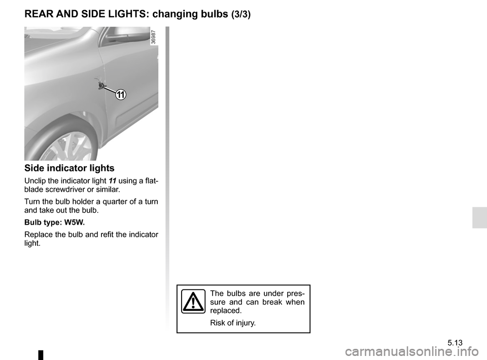
Side indicator lights
Unclip the indicator light 11 using a flat-
blade screwdriver or similar.
Turn the bulb holder a quarter of a turn
and take out the bulb.
Bulb type: W5W.
Replace the bulb and refit the indicator
light.
11
The bulbs are under pres-
sure and can break when
replaced.
Risk of injury.
REAR AND SIDE LIGHTS: changing bulbs (3/3)
Page 182 of 228
5.14
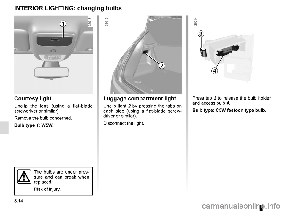
Courtesy light
Unclip the lens (using a flat-blade
screwdriver or similar).
Remove the bulb concerned.
Bulb type 1: W5W.
INTERIOR LIGHTING: changing bulbs
The bulbs are under pres-
sure and can break when
replaced.
Risk of injury.
Press tab 3 to release the bulb holder
and access bulb 4.
Bulb type: C5W festoon type bulb.Luggage compartment light
Unclip light 2 by pressing the tabs on
each side (using a flat-blade screw-
driver or similar).
Disconnect the light.
2
3
4
1
Page 183 of 228
5.15
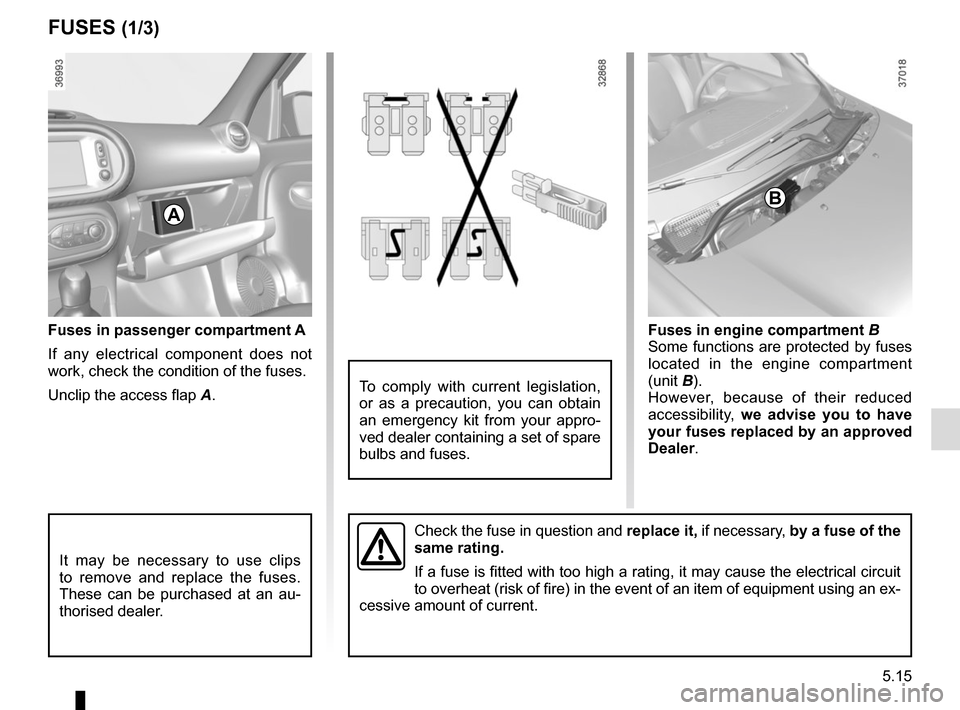
Fuses in passenger compartment A
If any electrical component does not
work, check the condition of the fuses.
Unclip the access flap A.
FUSES (1/3)
Fuses in engine compartment B
Some functions are protected by fuses
located in the engine compartment
(unit B).
However, because of their reduced
accessibility, we advise you to have
your fuses replaced by an approved
Dealer .
AB
It may be necessary to use clips
to remove and replace the fuses.
These can be purchased at an au-
thorised dealer.
Check the fuse in question and replace it, if necessary, by a fuse of the
same rating.
If a fuse is fitted with too high a rating, it may cause the electrical \
circuit
to overheat (risk of fire) in the event of an item of equipment using \
an ex-
cessive amount of current.
To comply with current legislation,
or as a precaution, you can obtain
an emergency kit from your appro-
ved dealer containing a set of spare
bulbs and fuses.
Page 184 of 228
5.16
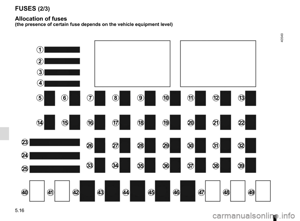
FUSES (2/3)
Allocation of fuses
(the presence of certain fuse depends on the vehicle equipment level)
1
2
3
4
5678910111213
141516171819222021
23
25
24
26272829303132
33343536373839
40414243444546474849
Page 185 of 228
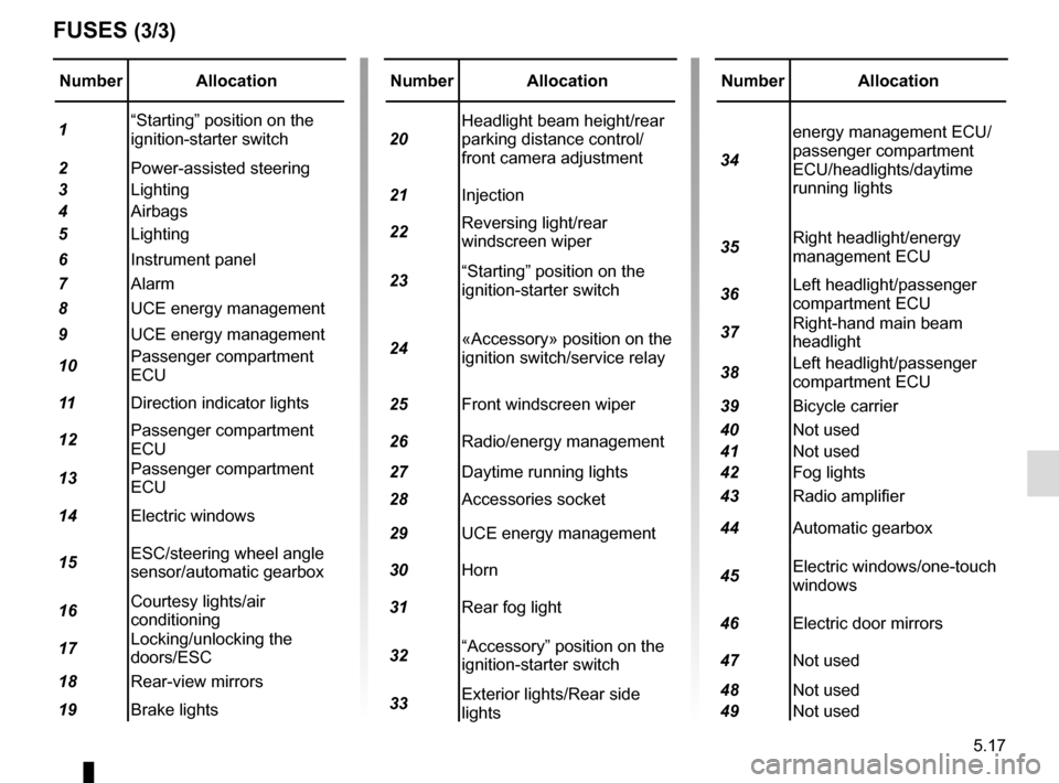
5.17
Number Allocation
1 “Starting” position on the
ignition-starter switch
2 Power-assisted steering
3 Lighting
4 Airbags
5 Lighting
6 Instrument panel
7 Alarm
8 UCE energy management
9 UCE energy management
10 Passenger compartment
ECU
11 Direction indicator lights
12 Passenger compartment
ECU
13 Passenger compartment
ECU
14 Electric windows
15 ESC/steering wheel angle
sensor/automatic gearbox
16 Courtesy lights/air
conditioning
17 Locking/unlocking the
doors/ESC
18 Rear-view mirrors
19 Brake lights
FUSES (3/3)
Number Allocation
20 Headlight beam height/rear
parking distance control/
front camera adjustment
21 Injection
22 Reversing light/rear
windscreen wiper
23 “Starting” position on the
ignition-starter switch
24 «Accessory» position on the
ignition switch/service relay
25 Front windscreen wiper
26 Radio/energy management
27 Daytime running lights
28 Accessories socket
29 UCE energy management
30 Horn
31 Rear fog light
32 “Accessory” position on the
ignition-starter switch
33 Exterior lights/Rear side
lightsNumber Allocation
34 energy management ECU/
passenger compartment
ECU/headlights/daytime
running lights
35 Right headlight/energy
management ECU
36 Left headlight/passenger
compartment ECU
37 Right-hand main beam
headlight
38 Left headlight/passenger
compartment ECU
39 Bicycle carrier
40 Not used
41 Not used
42 Fog lights
43 Radio amplifier
44 Automatic gearbox
45 Electric windows/one-touch
windows
46 Electric door mirrors
47 Not used
48 Not used
49 Not used
Page 186 of 228
5.18
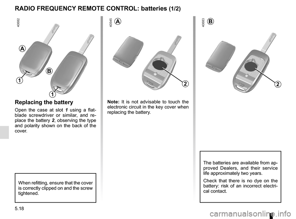
Replacing the battery
Open the case at slot 1 using a flat-
blade screwdriver or similar, and re-
place the battery 2, observing the type
and polarity shown on the back of the
cover. Note:
It is not advisable to touch the
electronic circuit in the key cover when
replacing the battery.
RADIO FREQUENCY REMOTE CONTROL: batteries (1/2)
2
When refitting, ensure that the cover
is correctly clipped on and the screw
tightened.
The batteries are available from ap-
proved Dealers, and their service
life approximately two years.
Check that there is no dye on the
battery: risk of an incorrect electri-
cal contact.
1
A
AB
B
1
2
Page 187 of 228
5.19
Operating faults
If the battery is too weak to ensure cor-
rect operation, you can still start and
lock/unlock the vehicle (please refer to
the information on “Locking/unlocking
the opening elements” in Section 1).
Do not throw away your
used batteries; give them to
an organisation responsible
for collecting and recycling
batteries.
RADIO FREQUENCY REMOTE CONTROL: batteries (2/2)
Page 188 of 228
5.20
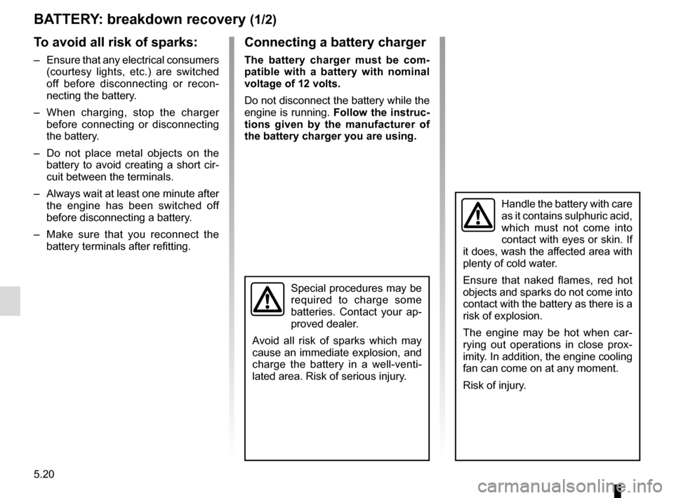
BATTERY: breakdown recovery (1/2)
To avoid all risk of sparks:
– Ensure that any electrical consumers (courtesy lights, etc.) are switched
off before disconnecting or recon-
necting the battery.
– When charging, stop the charger before connecting or disconnecting
the battery.
– Do not place metal objects on the battery to avoid creating a short cir-
cuit between the terminals.
– Always wait at least one minute after the engine has been switched off
before disconnecting a battery.
– Make sure that you reconnect the battery terminals after refitting.
Connecting a battery charger
The battery charger must be com-
patible with a battery with nominal
voltage of 12 volts.
Do not disconnect the battery while the
engine is running. Follow the instruc-
tions given by the manufacturer of
the battery charger you are using.
Special procedures may be
required to charge some
batteries. Contact your ap-
proved dealer.
Avoid all risk of sparks which may
cause an immediate explosion, and
charge the battery in a well-venti-
lated area. Risk of serious injury.
Handle the battery with care
as it contains sulphuric acid,
which must not come into
contact with eyes or skin. If
it does, wash the affected area with
plenty of cold water.
Ensure that naked flames, red hot
objects and sparks do not come into
contact with the battery as there is a
risk of explosion.
The engine may be hot when car-
rying out operations in close prox-
imity. In addition, the engine cooling
fan can come on at any moment.
Risk of injury.
Page 189 of 228
5.21
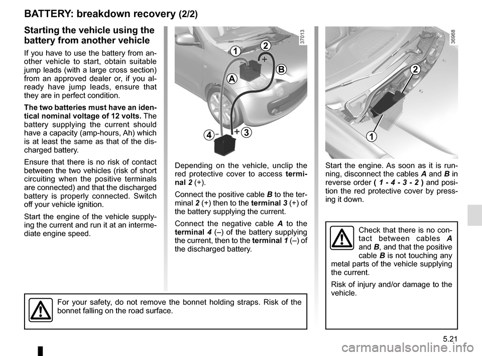
Start the engine. As soon as it is run-
ning, disconnect the cables A and B in
reverse order ( 1 - 4 - 3 - 2 ) and posi-
tion the red protective cover by press-
ing it down.
BATTERY: breakdown recovery (2/2)
Depending on the vehicle, unclip the
red protective cover to access termi-
nal 2 (+).
Connect the positive cable B to the ter-
minal 2 (+) then to the terminal 3 (+) of
the battery supplying the current.
Connect the negative cable A to the
terminal 4 (–) of the battery supplying
the current, then to the terminal 1 (–) of
the discharged battery.
Starting the vehicle using the
battery from another vehicle
If you have to use the battery from an-
other vehicle to start, obtain suitable
jump leads (with a large cross section)
from an approved dealer or, if you al-
ready have jump leads, ensure that
they are in perfect condition.
The two batteries must have an iden-
tical nominal voltage of 12 volts. The
battery supplying the current should
have a capacity (amp-hours, Ah) which
is at least the same as that of the dis-
charged battery.
Ensure that there is no risk of contact
between the two vehicles (risk of short
circuiting when the positive terminals
are connected) and that the discharged
battery is properly connected. Switch
off your vehicle ignition.
Start the engine of the vehicle supply-
ing the current and run it at an interme-
diate engine speed.
Check that there is no con-
tact between cables A
and B, and that the positive
cable B is not touching any
metal parts of the vehicle supplying
the current.
Risk of injury and/or damage to the
vehicle.
1
2
21
3
B
A
4
For your safety, do not remove the bonnet holding straps. Risk of the
bonnet falling on the road surface.
Page 190 of 228

5.22
Radio location 1
Unclip the blanking cover. The aerial, +
and – supply and speaker wire connec-
tions are located behind it.
Door speakers 2
To install any equipment, please con-
sult an authorised dealer.
FITTING A RADIO
1
2
– In all cases, it is very important to
follow the manufacturer’s instruc-
tions carefully.
– The specifications of the brack- ets and wires (available from our
network) vary depending on the
equipment level of your vehicle
and the type of radio.
Consult an approved Dealer to find out the correct part number.
– No work may be carried out on the vehicle’s electrical or radio
circuits, except by approved
dealers: an incorrectly connected
system may result in damage
being caused to the electrical
equipment and/or the compo-
nents connected to it.