light RENAULT TWINGO 2017 3.G Manual Online
[x] Cancel search | Manufacturer: RENAULT, Model Year: 2017, Model line: TWINGO, Model: RENAULT TWINGO 2017 3.GPages: 228, PDF Size: 6.76 MB
Page 171 of 228
5.3
TYRE INFLATION KIT (2/4)
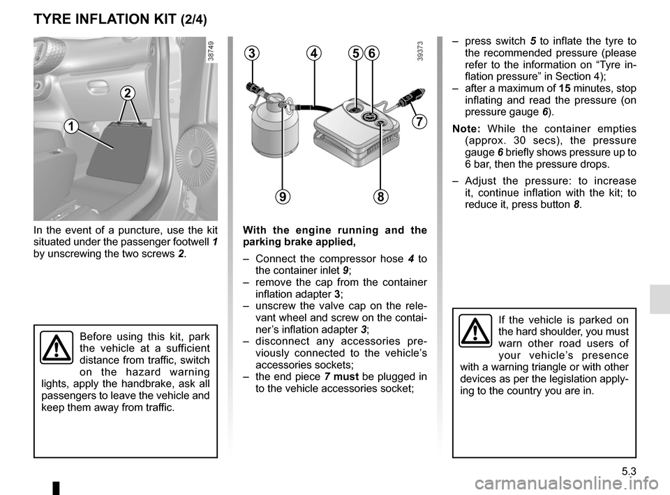
In the event of a puncture, use the kit
situated under the passenger footwell 1
by unscrewing the two screws 2.With the engine running and the
parking brake applied,
‚Äď Connect the compressor hose 4 to
the container inlet 9;
‚Äď remove the cap from the container inflation adapter 3;
‚Äď unscrew the valve cap on the rele- vant wheel and screw on the contai-
ner’s inflation adapter 3;
‚Äď disconnect any accessories pre- viously connected to the vehicle‚Äôs
accessories sockets;
‚Äď the end piece 7 must be plugged in
to the vehicle accessories socket;
563
Before using this kit, park
the vehicle at a sufficient
distance from traffic, switch
on the hazard warning
lights, apply the handbrake, ask all
passengers to leave the vehicle and
keep them away from traffic.
9
If the vehicle is parked on
the hard shoulder, you must
warn other road users of
your vehicle’s presence
with a warning triangle or with other
devices as per the legislation apply-
ing to the country you are in.
‚Äď press switch 5 to inflate the tyre to
the recommended pressure (please
refer to the information on “Tyre in-
flation pressure‚ÄĚ in Section 4);
‚Äď after a maximum of 15 minutes, stop inflating and read the pressure (on
pressure gauge 6).
Note: While the container empties (approx. 30 secs), the pressure
gauge 6 briefly shows pressure up to
6 bar, then the pressure drops.
‚Äď Adjust the pressure: to increase it, continue inflation with the kit; to
reduce it, press button 8.
7
4
8
1
2
Page 175 of 228
5.7
Tyre pressuresAdhere to the tyre pressures. The tyre
pressures should be checked at least
once a month and additionally before
any long journey (refer to the label af-
fixed to the edge of the driver’s door).
The pressures should be checked cold:
ignore higher pressures which may be
reached in hot weather or following a
high speed journey.Vehicle fitted with a tyre pressure
loss warning system
If under-inflated (puncture, low pres-
sure, etc.), the warning light
ÓĀá
on the instrument panel comes on.
See ‚ÄúTyre pressure loss warning‚ÄĚ in
Section 2.
Fitting new tyres
For safety reasons, this op-
eration must be carried out
by a specialist. Fitting differ-
ent tyres may change your
vehicle as follows:
‚Äď it may mean that your vehicle no longer conforms to current regu-
lations;
‚Äď it may change the way it handles when cornering;
‚Äď it may cause the steering to be heavy;
‚Äď it may affect the use of snow chains.
If the pressures cannot be checked
when the tyres are cold, increase the
pressures from 0.2 to 0.3 bar (or 3 PSI).
Never deflate a hot tyre.
Changing wheels around
TYRES (2/3)
Please be aware that a
poorly tightened or miss-
ing valve cap can make the
tyres less airtight and lead
to pressure loss.
Always use valve caps identical to
those fitted originally and tighten
them fully.
Incorrect tyre pressures
lead to abnormal tyre wear
and unusually hot running.
These are factors which
may seriously affect safety and lead
to:
‚Äď poor road holding,
‚Äď risk of bursting or tread separa- tion.
The pressure depends on the load
and the speed of use. Adjust the
pressure according to the condi-
tions of use (refer to the label affixed
to the edge of the driver’s door).
The front and rear wheels
have different dimensions.
For safety reasons, it is not
permitted to switch the front
wheels (tyres and/or rims) with the
rear wheels.
Page 177 of 228
5.9
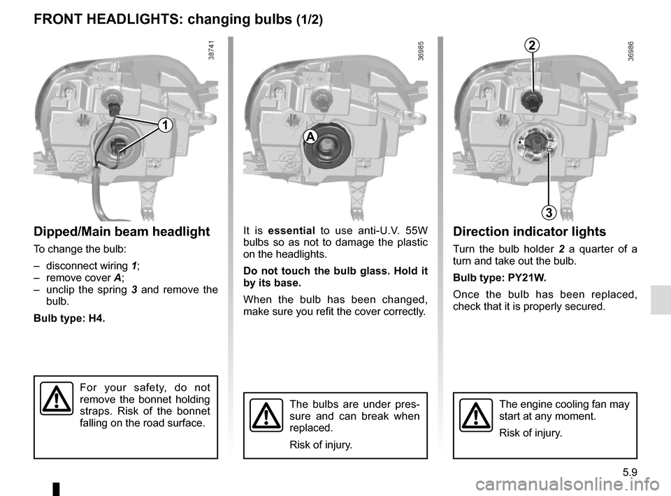
Direction indicator lights
Turn the bulb holder 2 a quarter of a
turn and take out the bulb.
Bulb type: PY21W.
Once the bulb has been replaced,
check that it is properly secured.
Dipped/Main beam headlight
To change the bulb:
‚Äď disconnect wiring 1;
‚Äď remove cover A;
‚Äď unclip the spring 3 and remove the
bulb.
Bulb type: H4.
FRONT HEADLIGHTS: changing bulbs (1/2)
The engine cooling fan may
start at any moment.
Risk of injury.
It is essential to use anti-U.V. 55W
bulbs so as not to damage the plastic
on the headlights.
Do not touch the bulb glass. Hold it
by its base.
When the bulb has been changed,
make sure you refit the cover correctly.
A
3
2
The bulbs are under pres-
sure and can break when
replaced.
Risk of injury.
1
For your safety, do not
remove the bonnet holding
straps. Risk of the bonnet
falling on the road surface.
Page 178 of 228
5.10
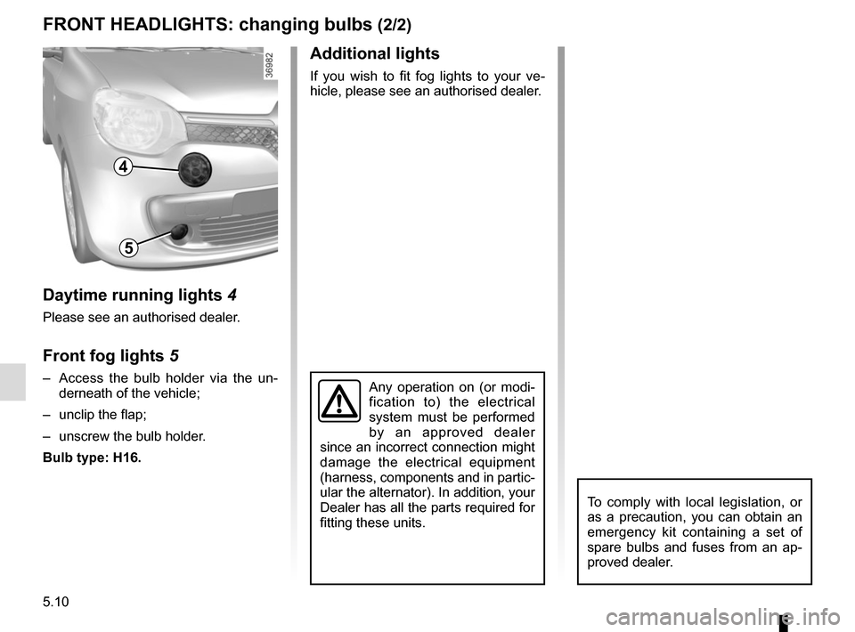
Daytime running lights 4
Please see an authorised dealer.
Front fog lights 5
‚Äď Access the bulb holder via the un-
derneath of the vehicle;
‚Äď unclip the flap;
‚Äď unscrew the bulb holder.
Bulb type: H16.Any operation on (or modi-
fication to) the electrical
system must be performed
by an approved dealer
since an incorrect connection might
damage the electrical equipment
(harness, components and in partic-
ular the alternator). In addition, your
Dealer has all the parts required for
fitting these units.
FRONT HEADLIGHTS: changing bulbs (2/2)
4
5
To comply with local legislation, or
as a precaution, you can obtain an
emergency kit containing a set of
spare bulbs and fuses from an ap-
proved dealer.
Additional lights
If you wish to fit fog lights to your ve-
hicle, please see an authorised dealer.
Page 179 of 228
5.11
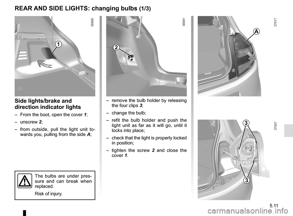
Side lights/brake and
direction indicator lights
‚Äď From the boot, open the cover 1;
‚Äď unscrew 2;
‚Äď from outside, pull the light unit to- wards you, pulling from the side A;
REAR AND SIDE LIGHTS: changing bulbs (1/3)
‚Äď remove the bulb holder by releasing
the four clips 3;
‚Äď change the bulb;
‚Äď refit the bulb holder and push the light unit as far as it will go, until it
locks into place;
‚Äď check that the light is properly locked in position;
‚Äď tighten the screw 2 and close the
cover 1.
3
3
12
A
The bulbs are under pres-
sure and can break when
replaced.
Risk of injury.
Page 180 of 228
5.12
REAR AND SIDE LIGHTS: changing bulbs (2/3)
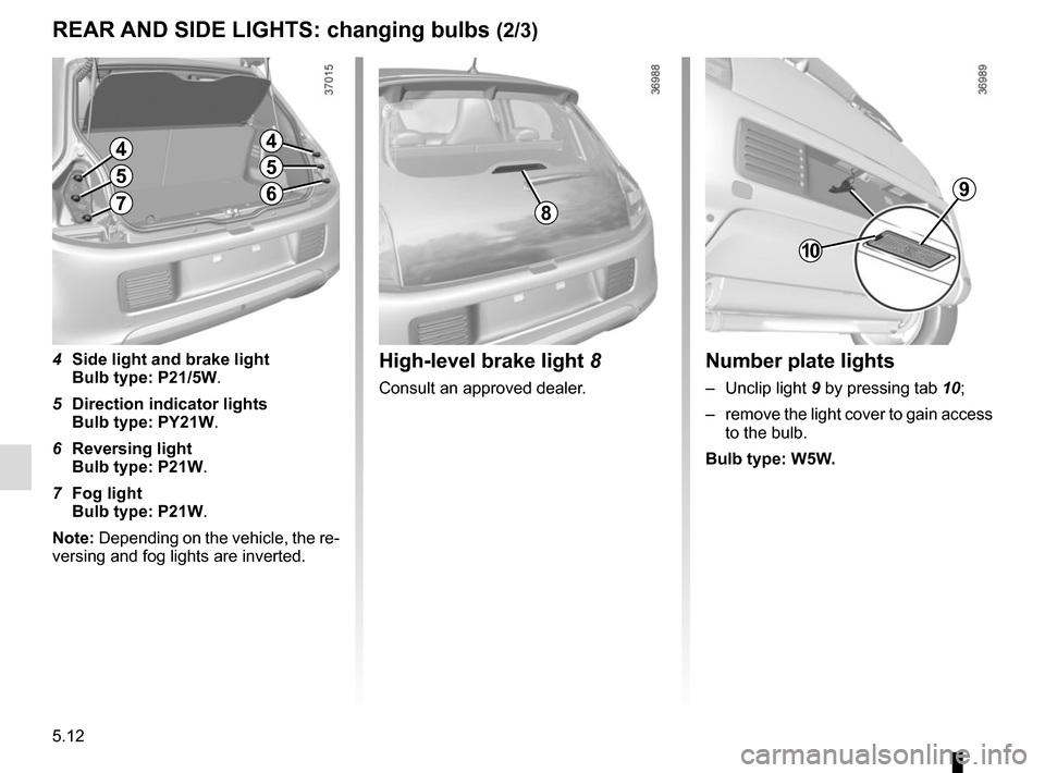
Number plate lights
‚Äď Unclip light 9 by pressing tab 10;
‚Äď remove the light cover to gain access to the bulb.
Bulb type: W5W.
10
9
High-level brake light 8
Consult an approved dealer.
8
44
4 Side light and brake light
Bulb type: P21/5W.
5 Direction indicator lights
Bulb type: PY21W.
6 Reversing light
Bulb type: P21W.
7 Fog light
Bulb type: P21W.
Note: Depending on the vehicle, the re-
versing and fog lights are inverted.
55
67
Page 181 of 228
5.13
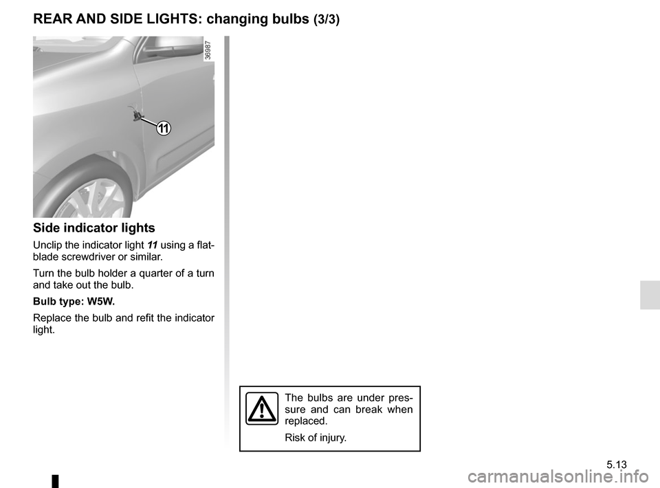
Side indicator lights
Unclip the indicator light 11 using a flat-
blade screwdriver or similar.
Turn the bulb holder a quarter of a turn
and take out the bulb.
Bulb type: W5W.
Replace the bulb and refit the indicator
light.
11
The bulbs are under pres-
sure and can break when
replaced.
Risk of injury.
REAR AND SIDE LIGHTS: changing bulbs (3/3)
Page 182 of 228
5.14
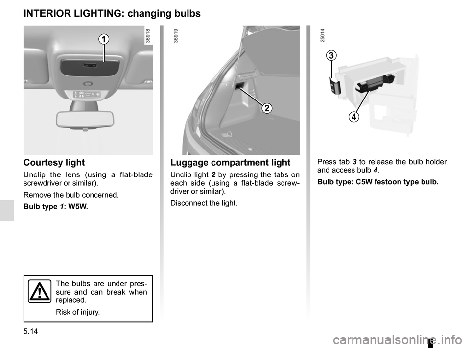
Courtesy light
Unclip the lens (using a flat-blade
screwdriver or similar).
Remove the bulb concerned.
Bulb type 1: W5W.
INTERIOR LIGHTING: changing bulbs
The bulbs are under pres-
sure and can break when
replaced.
Risk of injury.
Press tab 3 to release the bulb holder
and access bulb 4.
Bulb type: C5W festoon type bulb.Luggage compartment light
Unclip light 2 by pressing the tabs on
each side (using a flat-blade screw-
driver or similar).
Disconnect the light.
2
3
4
1
Page 185 of 228
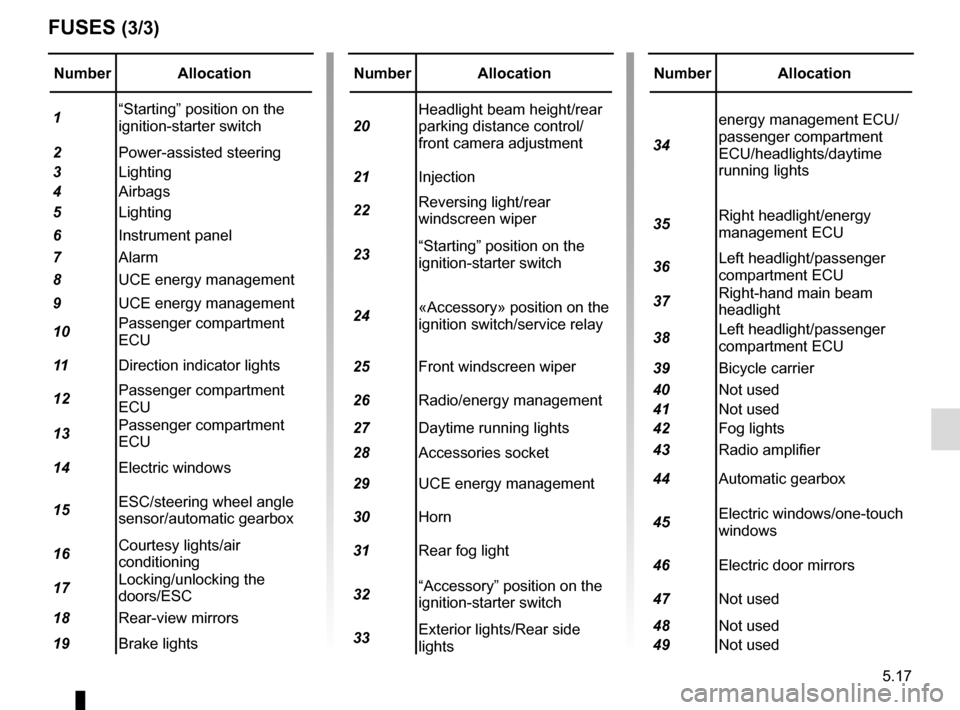
5.17
Number Allocation
1 ‚ÄúStarting‚ÄĚ position on the
ignition-starter switch
2 Power-assisted steering
3 Lighting
4 Airbags
5 Lighting
6 Instrument panel
7 Alarm
8 UCE energy management
9 UCE energy management
10 Passenger compartment
ECU
11 Direction indicator lights
12 Passenger compartment
ECU
13 Passenger compartment
ECU
14 Electric windows
15 ESC/steering wheel angle
sensor/automatic gearbox
16 Courtesy lights/air
conditioning
17 Locking/unlocking the
doors/ESC
18 Rear-view mirrors
19 Brake lights
FUSES (3/3)
Number Allocation
20 Headlight beam height/rear
parking distance control/
front camera adjustment
21 Injection
22 Reversing light/rear
windscreen wiper
23 ‚ÄúStarting‚ÄĚ position on the
ignition-starter switch
24 ¬ęAccessory¬Ľ position on the
ignition switch/service relay
25 Front windscreen wiper
26 Radio/energy management
27 Daytime running lights
28 Accessories socket
29 UCE energy management
30 Horn
31 Rear fog light
32 ‚ÄúAccessory‚ÄĚ position on the
ignition-starter switch
33 Exterior lights/Rear side
lightsNumber Allocation
34 energy management ECU/
passenger compartment
ECU/headlights/daytime
running lights
35 Right headlight/energy
management ECU
36 Left headlight/passenger
compartment ECU
37 Right-hand main beam
headlight
38 Left headlight/passenger
compartment ECU
39 Bicycle carrier
40 Not used
41 Not used
42 Fog lights
43 Radio amplifier
44 Automatic gearbox
45 Electric windows/one-touch
windows
46 Electric door mirrors
47 Not used
48 Not used
49 Not used
Page 188 of 228
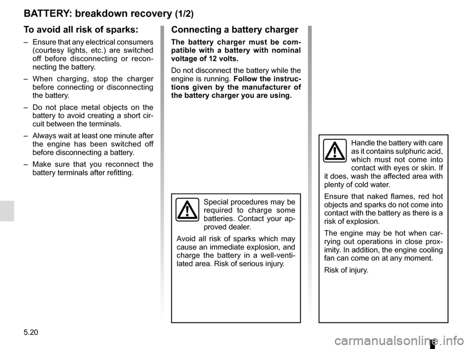
5.20
BATTERY: breakdown recovery (1/2)
To avoid all risk of sparks:
‚Äď Ensure that any electrical consumers (courtesy lights, etc.) are switched
off before disconnecting or recon-
necting the battery.
‚Äď When charging, stop the charger before connecting or disconnecting
the battery.
‚Äď Do not place metal objects on the battery to avoid creating a short cir-
cuit between the terminals.
‚Äď Always wait at least one minute after the engine has been switched off
before disconnecting a battery.
‚Äď Make sure that you reconnect the battery terminals after refitting.
Connecting a battery charger
The battery charger must be com-
patible with a battery with nominal
voltage of 12 volts.
Do not disconnect the battery while the
engine is running. Follow the instruc-
tions given by the manufacturer of
the battery charger you are using.
Special procedures may be
required to charge some
batteries. Contact your ap-
proved dealer.
Avoid all risk of sparks which may
cause an immediate explosion, and
charge the battery in a well-venti-
lated area. Risk of serious injury.
Handle the battery with care
as it contains sulphuric acid,
which must not come into
contact with eyes or skin. If
it does, wash the affected area with
plenty of cold water.
Ensure that naked flames, red hot
objects and sparks do not come into
contact with the battery as there is a
risk of explosion.
The engine may be hot when car-
rying out operations in close prox-
imity. In addition, the engine cooling
fan can come on at any moment.
Risk of injury.