engine RENAULT TWINGO RS 2009 2.G Air Conditioning Owner's Manual
[x] Cancel search | Manufacturer: RENAULT, Model Year: 2009, Model line: TWINGO RS, Model: RENAULT TWINGO RS 2009 2.GPages: 122
Page 85 of 122
62A-4
AIR CONDITIONING
Air conditioning: Check
AIR CONDITIONING or CLIMATE CONTROL
62A
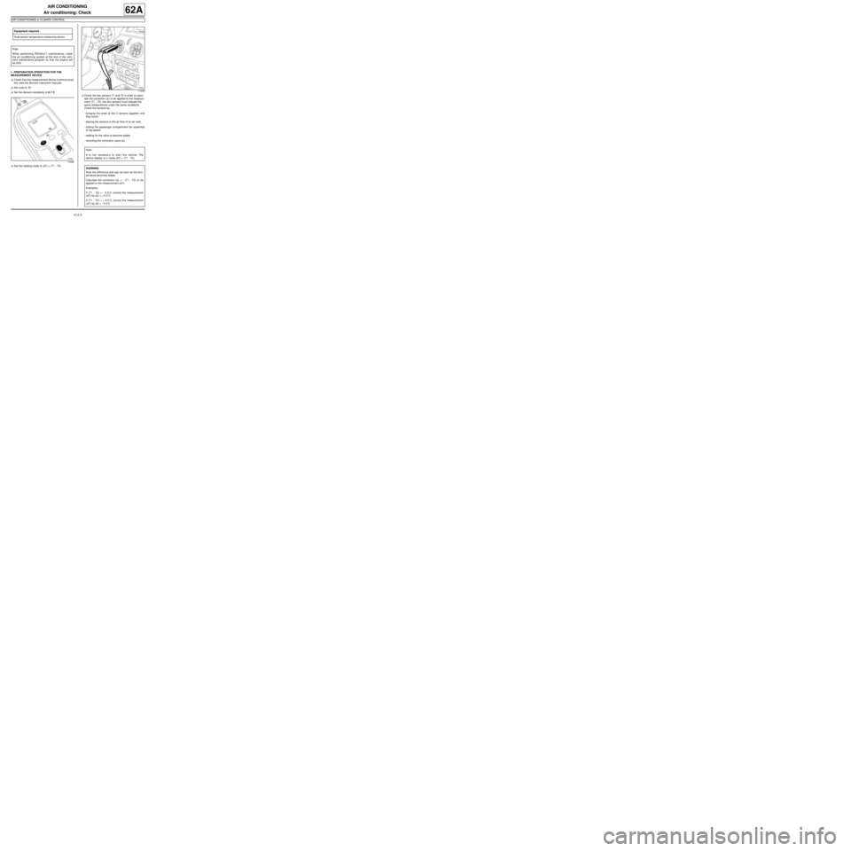
I - PREPARATION OPERATION FOR THE
MEASUREMENT DEVICE
aCheck that the measurement device functions prop-
erly (see the device's instruction manual).
aSet units to ˚C.
aSet the device's sensitivity to 0.1˚C.
aSet the reading mode to (∆T) = (T1 - T2)aCheck the two sensors T1 and T2 in order to calcu-
late the correction (∆) to be applied to the measure-
ment (T1 - T2). the two sensors must indicate the
same measurement under the same conditions.
Check the sensors by:
-bringing the ends of the 2 sensors together until
they touch,
-placing the sensors in the air flow of an air vent,
-setting the passenger compartment fan assembly
to top speed.
-waiting for the value to become stable.
-recording the correction value (∆). Equipment required
Dual-sensor temperature measuring device
Note:
When performing RENAULT maintenance, check
the air conditioning system at the end of the vehi-
cle's maintenance program so that the engine will
be cold.
119360
119358
Note:
It is not necessary to start the vehicle. The
device display is in mode (∆T) = (T1 - T2).
WARNING
Note the diff erence and sign as soon as the tem-
per ature becomes stable.
Calculate the correction (∆) = - (T1 - T2) to be
applied to the measurement (∆T).
Examples:
If (T1 - T2) = - 0.3˚C, correct the measurement
(∆T) by (∆) = + 0.3˚C
If (T1 - T2) = + 0.3˚C, correct the measurement
(∆T) by (∆) = - 0.3˚C
Page 86 of 122
62A-5
AIR CONDITIONING
Air conditioning: Check
AIR CONDITIONING or CLIMATE CONTROL
62A
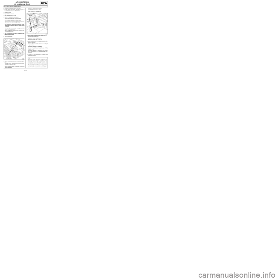
II - VEHICLE PREPARATION OPERATION
aPut the vehicle in the shade, where the temperature
is greater than or equal to 15˚C minimum.
aClose the bonnet.
aOpen the front windows.
aStart the engine and let it idle.
aSet the air conditioning controls with:
-recirculation mode in the external position,
-the ventilation distribution in "face" mode,
-the temperature control to coldest temperature set-
ting in front (and at the back, if it exists),
-the speed of the passenger compartment fan as-
sembly set to maximum (switch off the rear control
if it exists),
-the front side and centre air vents open with the
vanes in a neutral position,
-the air conditioning system must be turned on (indi-
cator light illuminated).
aWait 5 minutes with the engine idling before tak-
ing any measurements.
III - MEASUREMENTS
aRecord the air temperature at the scuttle panel grille
(T3).
-open the bonnet, depending on the vehicle, to ac-
cess the scuttle panel grille.
-place the sensor where air is drawn through the
scuttle panel grille.-wait for the value to become stable.
-record the T3 temperature value.
-close the bonnet if it was opened.
aRecord the air temperature at the left air vent (T1),
and at the right air vent (T2).
-fit sensor T1 in the left air vent (1) .
-fit sensor T2 in the right air vent (2) .
aRecord the differences in temperature once the (∆T)
value has stabilised:
-between T3 and the higher of values T1 or T2, (T3
- highest value).
-record this difference in temperature.
-between T1 and T2 (read the (∆T) value (T1-T2)
display mode).
-record the difference in temperature (∆T) accord-
ing to the correction (∆) to be applied to the mea-
surement.
aIf the (∆T)=(T1-T2) measurement is unstable, follow
the procedure below:
119359
119357
Note:
Depending on the vehicle's air conditioning sys-
tem programming, this check method may not be
applicable because the engine cooling fan
assembly has been activated. Its operation ren-
ders the (∆Τ) value between T1 and T2 unstable.
To eliminate this error, the fan assembly must be
activated for the entire period over which temper-
ature T1 and T2 measurements are recorded.
Page 87 of 122
62A-6
AIR CONDITIONING
Air conditioning: Check
AIR CONDITIONING or CLIMATE CONTROL
62A
aActivate the engine cooling fan assembly operation
by modifying the engine speed.
-stabilise the engine speed at 2000 rpm while T1
and T2 temperature measurements are being re-
corded.
-check that the engine cooling fan assembly operat-
ing.
-record the temperatures by following the instruc-
tions given in the paragraph MEASUREMENTS.
IV - FAULT FINDING PROCEDURE
aThe following two following conditions must be met:
-the difference between T3 and the higher of the two
values T1 or T2, must be greater than or equal to
5˚C,
-the difference between T1 and T2 must be less
than or equal to 2˚C.
Note:
If one of these two conditions is not met, then the
air conditioning system is not working properly.
Should this be the case, refer to the fault finding
procedure for the air conditioning system for the
vehicle concerned.
Page 88 of 122
62A-7
AIR CONDITIONING
Refrigerant circuit: Check
AIR CONDITIONING or CLIMATE CONTROL
62A
There are several types of detector:
-electronic detectors,
-trace detectors.
Check that the air conditioning system is operating cor-
rectly (see 62A, Air conditioning, Air conditioning:
Check, page 62A-4) .
REFRIGERANT CIRCUIT SEALING CHECKING
OPERATION
1 - Electronic detectors:
a
aSwitch on the electronic detector.
aStart the engine.
aLet the air conditioning system run for 15 minutes.
aSwitch off the engine.aCheck the sealing of the refrigerant circuit using the
electronic trace detector (follow the trace of the cir-
cuit as closely as possible, to limit variations due to
other gases).
2 - Trace detectors
a
aCheck for dye on the cold loop components with the
ultraviolet light.
aInject the dye.
aStart the engine.
aLet the air conditioning system run for 15 minutes.
aSwitch off the engine.
aCheck the refrigerant circuit sealing by scanning the
circuit with the ultraviolet light.
aAffix a label (supplied with the dye capsule), to indi-
cate that dye has been used (as close as possible to
the filler valves). Equipment required
Diagnostic tool
IMPORTANT
Consult the safety and cleanliness advice and oper-
ation recommendations before carrying out any
repair (see 62A, Air conditioning, Air condition-
ing: Precautions for the repair, page 62A-1) .
Note:
After any work on air conditioning circuit leaks on
the Laguna II, Vel Satis and Espace IV, check that
filling fault DF033 Refrigerant is not present, using
the Diagnostic tool. If it is present, clear it. The
compressor cannot operate until the fault is cleared.
Note:
To carry out an after repair check, use the proce-
dure for the electronic detector (1). To carry out a
more thorough check for leaks, use a trace detector
(2).
WARNING
Consult the device's operating manual to avoid
incorrect use.
Note:
If replacing a defective part (see 62A, Air condi-
tioning).
WARNING
Consult the device's operating manual to avoid
incorrect use.
WARNING
To avoid damaging the cold loop components
(corrosions , etc.), do not use dye if the traces
reveal that some product has already been
injected.
Note:
If replacing a defective part (see 62A, Air condi-
tioning).
Page 89 of 122
62A-8
AIR CONDITIONING
Refrigerant circuit: Draining - Filling
AIR CONDITIONING or CLIMATE CONTROL
62A
Equipment required
refrigerant charging station
IMPORTANT
Consult the safety and cleanliness advice and oper-
ation recommendations before carrying out any
repair (see 62A, Air conditioning, Air condition-
ing: Precautions for the repair, page 62A-1) .
WARNING
Consult the device's operating manual to avoid
incorrect use.
WARNING
To avoid damaging the cold loop components (cor-
rosions, etc.), do not use dye if the traces reveal
that some product has already been injected.
Note:
A summary table gives the quantities of refrigerant
in the system according to the engine type (see
62A, Air conditioning, Air conditioning: Parts
and consumables for the repair, page 62A-2) .
Page 90 of 122
62A-9
AIR CONDITIONING
Refrigerant circuit: Draining - Filling
AIR CONDITIONING or CLIMATE CONTROL
62A
I - RECOVERING REFRIGERANT FLUID
a
When draining or checking the refrigerant fill load,
three scenarios are to be taken into account:
-the engine is running and the air conditioning is in
operation (A),
-the engine is running but the air conditioning is not
in operation (B),
-the engine is not running nor is the air conditioning
in operation (C).
aScenario A:
-Operate the air conditioning until the cooling fan
assembly is triggered twice,
-Switch off the engine,
-drain for the first time (note down the original val-
ue),
-wait 15 minutes,
-check that the relative pressure is no more than 0
bar,
-repeat the cycles until the relative pressure is equal
to or less than 0 bar,
-add together the values of the various draining op-
erations; the fill is confirmed as being correct if the
volume of refrigerant fluid is the specified fill +35g
or -100g.
Scenario B:
-run the engine until the cooling fan is triggered
twice,
-Switch off the engine,-drain for the first time (note down the value),
-wait 15 minutes,
-run the engine until the cooling fan is triggered
twice,
-Switch off the engine,
-drain for the second time (note down the value),
-repeat the cycles until the relative pressure is equal
to or less than 0 bar,
-add together the values of the various draining op-
erations; the fill is confirmed as being correct if the
volume of refrigerant fluid is the specified fill +35g
or -100g.
Scenario C:
-drain for the first time (note down the value),
-wait 2 hours,
-repeat the cycles until the relative pressure is equal
to or less than 0 bar,
-add together the values of the various draining op-
erations; the fill is confirmed as being correct if the
volume of refrigerant fluid is the specified fill +35g
or -100g.
II - CREATING A VACUUM
aIt is essential to carry out vacuum extraction correct-
ly before loading, otherwise the air conditioning will
not work properly.
There are two scenarios to consider:
-vacuum created immediately after discharge (sce-
nario A),
-vacuum created after an interval of several hours
or days (scenario B).
Scenario A:
-creation of a vacuum takes 20 minutes.
Scenario B:
-creation of a vacuum takes 45 minutes to elimi-
nate any trace of moisture.
aTest the seal once the vacuum has been created
(some stations do this automatically).
III - FILLING
aFill up the refrigerant circuit using the refrigerant
charging station. Note:
-If the air conditioning circuit is fitted with a sin-
gle filler valve, some filling equipment only
requires the use of the high pressure pipe (refer
to the filling station instructions).
-Depending on the situation, run the system for
a few minutes before recovering the coolant to
improve drainage.
Note:
It is essential to follow these procedures to pre-
vent:
- gas escaping when the circuit is opened,
- pollution of the environment through the release
of gas into the atmosphere when the circuit is
opened or when a vacuum is created.
Page 99 of 122
62A-18
AIR CONDITIONING
Compressor: Removal - Refitting
AIR CONDITIONING or CLIMATE CONTROL
62A
REMOVAL
I - REMOVAL PREPARATION OPERATION
aPosition the vehicle on a two-post lift (see Vehicle:
Towing and lifting) (02A, Lifting equipment).aDrain the refrigerant circuit using a refrigerant
charging station (see 62A, Air conditioning, Re-
frigerant circuit: Draining - Filling, page 62A-8) .
aDisconnect the battery (see ) (80A, Battery).
aRemove:
-the front wheels (see Wheel: Removal - Refitting)
(35A, Wheels and tyres),
-the front wheel arch liners (see Front wheel arch
liner: Removal - Refitting) (55A, Exterior protec-
tion),
-the front bumper (see Front bumper: Removal -
Refitting) (55A, Exterior protection),
-the accessories belt (see Accessories belt: Re-
moval - Refitting) (10A, Engine and peripherals).
II - OPERATION FOR REMOVAL OF PART
CONCERNED
aRemove the bolts (1) from the connecting pipes on
the compressor. Equipment required
refrigerant charging station
compressed air nozzle
IMPORTANT
To avoid all risk of damage to the systems, apply
the safety and cleanliness instructions and opera-
tion recommendations before carrying out any
repair:
- (see 62A, Air conditioning, Air conditioning:
Precautions for the repair, page 62A-1) ,
- (see Vehicle: Precautions for the repair) (01D,
Mechanical introduction).
Note:
Use blanking plugs for the fuel circuits with part
numbers 77 01 208 229 or 77 01 476 857 to plug
any openings exposed to the open air. They must
be clean. Do not use any which have already been
used to plug a fuel circuit.
WARNING
To prevent moisture from entering the system,
place plugs on the cold loop components which are
open to the air.
WARNING
In order to avoid any refrigerant leaks, do not dam-
age (deform, twist, etc.) the pipe.
WARNING
Consult the device's operating manual to avoid
incorrect use.
121175
Page 101 of 122
62A-20
AIR CONDITIONING
Compressor: Removal - Refitting
AIR CONDITIONING or CLIMATE CONTROL
62A
aUse a compressed air nozzle to blow on the sur-
face and the seal of the connecting pipe.
aLubricate the surface of the connecting pipe and the
seal with air conditioning oil (see 62A, Air condi-
tioning, Air conditioning: Parts and consum-
ables for the repair, page 62A-2) .
aRemove the blanking plugs.
II - REFITTING OPERATION FOR PART
CONCERNED
aRefit the compressor.
aConnect the compressor connector.
aPosition the compressor connecting pipes.
aRefit:
-the bolts of the connecting pipes on the compres-
sor,
-the bolt of the connecting pipe bracket on the com-
pressor.
III - FINAL OPERATION
aRefit:
-the accessories belt (see Accessories belt: Re-
moval - Refitting) (10A, Engine and peripherals),
-the front bumper (see Front bumper: Removal -
Refitting) (55A, Exterior protection),
-the front wheel arch liners (see Front wheel arch
liner: Removal - Refitting) (55A, Exterior protec-
tion),-the front wheels (see Wheel: Removal - Refitting)
(35A, Wheels and tyres).
aConnect the battery (see ) (80A, Battery).
aConsult the amount of refrigerant and oil required
before filling the air conditioning circuit (see 62A, Air
conditioning, Air conditioning: Parts and con-
sumables for the repair, page 62A-2) .
aFill the refrigerant circuit using a refrigerant charg-
ing station (see 62A, Air conditioning, Refriger-
ant circuit: Draining - Filling, page 62A-8) .
aIn the event of replacement, apply the after repair
procedure:
-Switch on the ignition,
-Check that the air conditioning is off,
-Switch the ventilation to speed 2,
-Put the temperature setting at minimum,
-Select the air recirculation position,
-Start the engine.
-Run the air conditioning in manual mode (in the
case of climate control do not press auto),
-Run the engine at idle speed for 3 minutes with air
conditioning,
-Switch off the engine.
aCheck for leaks (see 62A, Air conditioning, Refrig-
erant circuit: Check, page 62A-7) .
aCheck that the air conditioning system is operating
correctly (see 62A, Air conditioning, Air condi-
tioning: Check, page 62A-4) .
143882