check engine RENAULT TWINGO RS 2009 2.G Chasiss - Power Assisted Steering User Guide
[x] Cancel search | Manufacturer: RENAULT, Model Year: 2009, Model line: TWINGO RS, Model: RENAULT TWINGO RS 2009 2.GPages: 54
Page 28 of 54

36B-28
MR-413-X44-36B000$536.mif
V2
POWER – ASSISTED STEERING
Fault finding – Conformity check
EPAS
Vdiag No.: 04 - 08
36B
MAIN SCREEN
NOTESOnly carry out this conformity check after a complete check with the diagnostic tool.
Application conditions: engine at idle speed, no movement of the steering
wheel, front wheels straight ahead.
FunctionParameter or Status
Checked or ActionDisplay and notes Fault finding
Wire informationPR003:Vehicle speed0 mphIn the event of a fault, apply the
interpretation of parameter
PR003.
PR004:Engine speed850 +/- 50 rpmIn the event of a fault, apply the
interpretation of parameter
PR004.
Assistance PR001:Torque applied
to the steering
wheel0 Nm (+ 0.2 Nm)In the event of a fault, apply the
interpretation of parameter
PR001.
Steering wheel
angle
(Vdiag 04 only)PR121:Steering wheel
angle- 5˚ < X < 5˚In the event of a fault, apply the
interpretation of parameter
PR121.
Page 29 of 54
36B-29
MR-413-X44-36B000$536.mif
V2
POWER – ASSISTED STEERING
Fault finding – Conformity check
EPAS
Vdiag No.: 04 - 08
36B
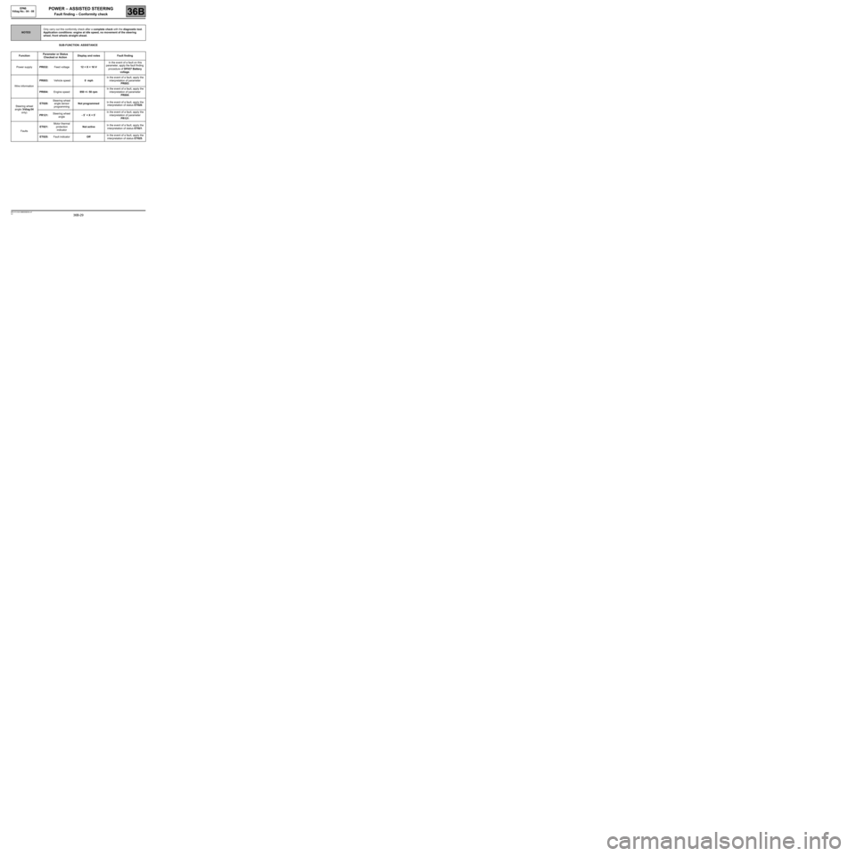
SUB-FUNCTION: ASSISTANCE
NOTESOnly carry out this conformity check after a complete check with the diagnostic tool.
Application conditions: engine at idle speed, no movement of the steering
wheel, front wheels straight ahead.
FunctionParameter or Status
Checked or ActionDisplay and notes Fault finding
Power supplyPR032:Feed voltage12 < X < 16 VIn the event of a fault on this
parameter, apply the fault finding
procedure of DF037 Battery
voltage.
Wire informationPR003: Vehicle speed0 mphIn the event of a fault, apply the
interpretation of parameter
PR003.
PR004:Engine speed850 +/- 50 rpmIn the event of a fault, apply the
interpretation of parameter
PR004.
Steering wheel
angle (Vdiag 04
only)ET020:Steering wheel
angle sensor
programmingNot programmedIn the event of a fault, apply the
interpretation of status ET020.
PR121:Steering wheel
angle- 5˚ < X < 5˚In the event of a fault, apply the
interpretation of parameter
PR121.
FaultsET021:Motor thermal
protection
indicatorNot activeIn the event of a fault, apply the
interpretation of status ET021.
ET025:Fault indicatorOffIn the event of a fault, apply the
interpretation of status ET025.
Page 30 of 54
36B-30
MR-413-X44-36B000$536.mif
V2
POWER – ASSISTED STEERING
Fault finding – Conformity check
EPAS
Vdiag No.: 04 - 08
36B
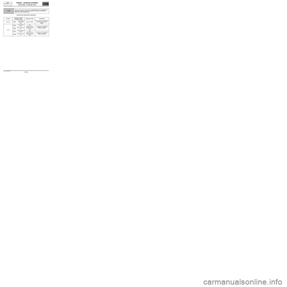
SUB-FUNCTION: ASSISTANCE (CONTINUED)
NOTESOnly carry out this conformity check after a complete check with the diagnostic tool.
Application conditions: engine at idle speed, no movement of the steering
wheel, front wheels straight ahead.
FunctionParameter or Status
Checked or ActionDisplay and notes Fault finding
AssistancePR001:Torque applied
to the steering
wheel0 Nm (+ 0.2 Nm)In the event of a fault, apply the
interpretation of parameter
PR001.
OutputPR132: Current setpoint
(45 A)0 A
Note: these two
parameters must be
approximately the
same.In the event of a fault, apply the
interpretation of parameters
PR132 and PR130.
PR130: Motor power (45
A)
PR131: Current setpoint
(60 A)0 A
Note: these two
parameters must be
approximately the
same.In the event of a fault, apply the
interpretation of parameters
PR131 and PR129.
PR129: Motor power (60
A)
Page 38 of 54
36B-38
MR-413-X44-36B000$804.mif
V2
POWER – ASSISTED STEERING
Fault finding – Interpretation of parameters
EPAS
Vdiag No.: 04 - 08
36B
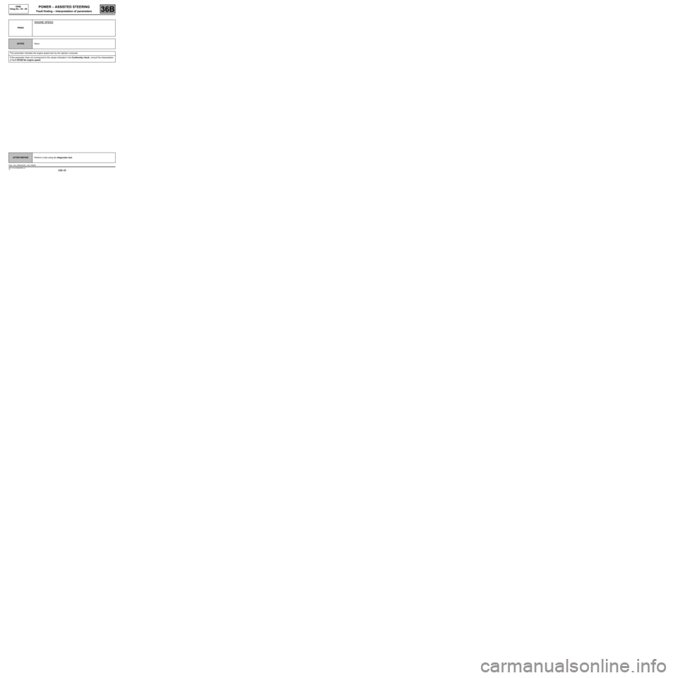
PR004
ENGINE SPEED
NOTESNone.
This parameter indicates the engine speed sent by the injection computer.
If the parameter does not correspond to the values indicated in the Conformity check, consult the interpretation
of fault DF028 No engine speed.
AFTER REPAIRPerform a test using the diagnostic tool.
DAE_V04_PR004/DAE_V08_PR004
Page 43 of 54
36B-43
MR-413-X44-36B000$938.mif
V2
36B
POWER – ASSISTED STEERING
Fault finding – Fault finding Chart
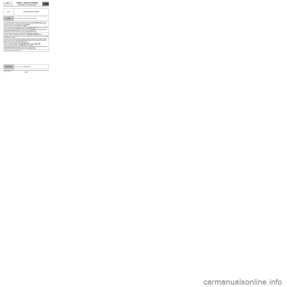
ALP 1 No dialogue with the computer
NOTESUse the Technical Note wiring diagram for New Twingo.
Try to establish dialogue with a computer on another vehicle to check that the diagnostic tool is not faulty.
If the tool is not faulty and no dialogue is established with any other computer of the same vehicle, check the
tightness and condition of the battery terminals (see 80A, Battery).
Check the charging circuit (see 16A, Starting - Charging).
With connector A of component 502 and the connector of components 1222 and 1094 disconnected, check the
continuity and insulation of connection HK between components 502 and 225.
If the connection(s) are faulty and there is a repair method (see Technical Note 6015A, Repairing electrical
wiring, W iring: Precautions for repair), repair the wiring, otherwise replace it.
If the checks reveal no faults, check the conformity of components 1022 and 1094.
Check the condition and the position of the 80 A fuse in the engine fuse and relay box.
Check the condition and the position of fuse F3 (15 A) in the passenger compartment fuse box.
With the ignition on and the engine stopped, check for a voltage equal to the battery voltage on connections BP81
and AP23 against earth ML.
Connectors of component 502 disconnected, check the condition and conformity of the connectors and clips.
If the connector is faulty (see Technical Note 6015A, Repairing electrical wiring, Wiring: Precautions for
repair), repair the connector, otherwise replace the wiring.
With the connectors of components 597 and 1016 disconnected:
Check the continuity and insulation of connection BP81 between components 502 and 597.
Check the continuity and insulation of connection AP23 between components 502 and 1016.
Check the continuity and insulation of connection ML of component 502.
If the connection(s) are faulty and there is a repair method (see Technical Note 6015A, Repairing electrical
wiring, W iring: Precautions for repair), repair the wiring, otherwise replace it.
If the checks reveal no faults, check the conformity of components 597 and 1016.
If the fault is still present, contact Techline.
AFTER REPAIRPerform a test using the diagnostic tool.
DAE_V04_ALP1/ DAE_V08_ALP1
EPAS
Vdiag No.: 04 - 08
MR-413-X44-36B000$938.mif
Page 52 of 54
36B-52
MR-413-X44-36B000$938.mif
V2
POWER – ASSISTED STEERING
Fault finding – Fault finding Chart
EPAS
Vdiag No.: 04 - 08
36B
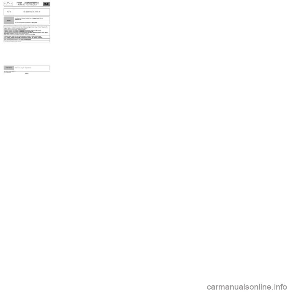
ALP 10 NO ASSISTANCE ON START-UP
NOTESOnly consult this customer complaint after a complete check with the
diagnostic tool.
Use the Technical Note wiring diagram for New Twingo.
Connectors of component 502 disconnected, check the condition and conformity of the connectors and clips.
If the connector is faulty (see Technical Note 6015A, Repairing electrical wiring, Wiring: Precautions for
repair), repair the connector, otherwise replace the wiring.
With the connector of component 1016 disconnected:
Check the continuity and insulation of connection AP23 between components 502 and 1016.
Check the continuity and insulation of connection ML of component 502.
If the connection or connections are faulty (see Technical Note 6015A, Repairing electrical wiring, Wiring:
Precautions for repair), repair the wiring, otherwise replace it.
If the checks reveal no faults, perform a conformity check of component 1016.
Check the battery voltage and carry out any operations necessary to obtain a correct voltage
(10 V < battery voltage < 16 V, see MR 411 Mechanical systems, 16A, Starting - Charging).
Apply the fault finding procedure for fault DF028 No engine speed.
If the fault is still present, contact Techline.
AFTER REPAIRPerform a test using the diagnostic tool.
DAE_V04_ALP10 /DAE_V08_ALP10