brake sensor RENAULT TWINGO RS 2009 2.G Chasiss Workshop Manual
[x] Cancel search | Manufacturer: RENAULT, Model Year: 2009, Model line: TWINGO RS, Model: RENAULT TWINGO RS 2009 2.GPages: 281
Page 4 of 281
Contents
37A MECHANICAL COMPONENT CONTROLS
Master cylinder: Removal -
Refitting 37A-1
Brake servo non-return
valve: Removal - Refitting 37A-11
Brake servo: Remo val -
Refitting 37A-14
Vacuum pump: Removal -
Refitting 37A-25
Pedal assembly: List and
location of components 37A-27
Accelerator pedal: Removal -
Refitting 37A-29
Brake pedal: Removal -
Refitting 37A-31
Brake pedal switch: Removal
- Refitting 37A-42
Parking br ake lever: Removal
- Refitting 37A-46
Parking brake lever:
Adjustment 37A-48
Clutch control: List and
location of components 37A-49
Clutch cable: Removal -
Refitting 37A-51
Clutch pedal switch:
Removal - Refitting 37A-52
Clutch circuit: Bleed 37A-54
Clutch master cylinder:
Removal - Refitting 37A-61
Clutch circuit: Removal -
Refitting 37A-63
Manual gear control: List and
location of components 37A-65
Gear control unit: Removal -
Refitting 37A-67
Gear control unit: Adjustment 37A-71
Parking brake cables:
Removal - Refitting 37A-74
Brake servo: Check 37A-7838C ANTI-LOCK BRAKING SYSTEM
Hydraulic brake unit: List and
location of components 38C-1
Hydraulic brake unit:
Removal - Refitting 38C-2
Front wheel speed sensor:
Removal - Refitting 38C-15
Rear wheel speed sensor :
Removal - Refitting 38C-17
Lateral acceleration and yaw
sensor: Removal - Refitting 38C-19
Braking computer: Removal -
Refitting 38C-21
Page 66 of 281
31A-23
FRONT AXLE COMPONENTS
Front driveshaft hub carrier: Removal - Refitting
31A
REMOVAL
I - REMOVAL PREPARATION OPERATION
aPosition the vehicle on a two-post lift (see Vehicle:
Towing and lifting) (MR 411, 02A, Lifting equip-
ment).
aRemove:
-the front wheel on the side in question (see 35A,
Wheels and tyres, Wheel: Removal - Refitting,
page 35A-1) ,
-the front brake pads of the side in question (see
31A, Front axle components, Front brake pads:
Removal - Refitting, page 31A-1) ,
aRemove:
-the front brake calliper mounting (see 31A, Front
axle components, Front brake calliper mount-
ing: Removal - Refitting, page 31A-14) ,
-the front brake disc (see 31A, Front axle compo-
nents, Front brake disc: Removal - Refitting,
page 31A-19) ,
-the front wheel speed sensor on the hub carrier
(see 38C, Anti-lock braking system, Front wheel
speed sensor: Removal - Refitting, page 38C-
15) .II - OPERATION FOR REMOVAL OF PART
CONCERNED
aPosition the (Rou. 604-01).
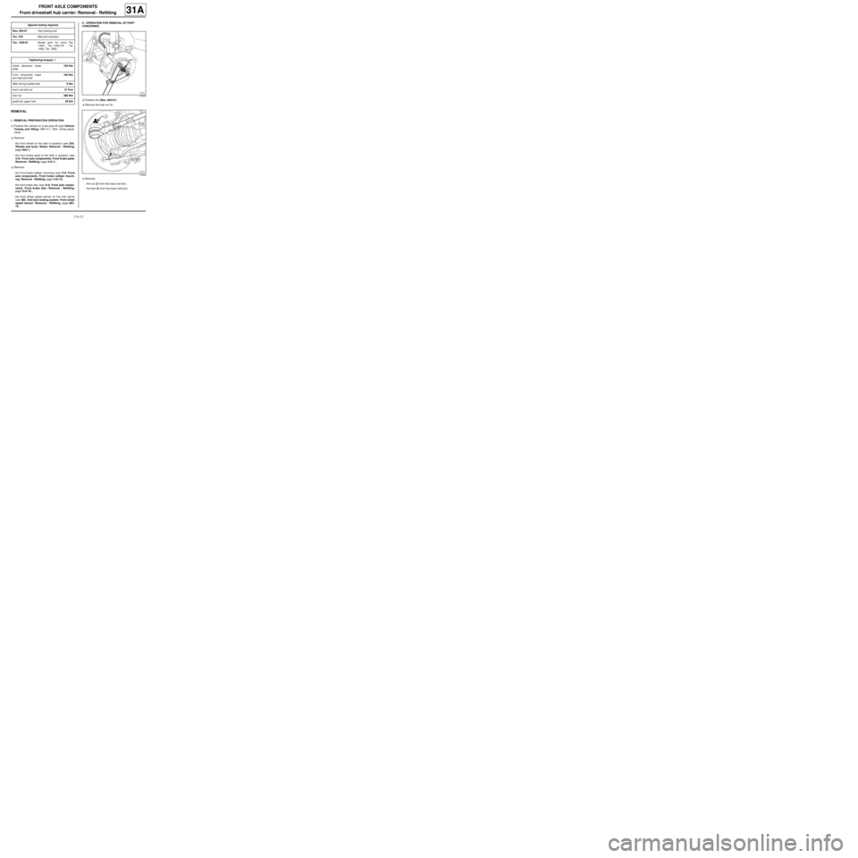
aRemove the hub nut (1) .
aRemove:
-the nut (2) from the track rod end,
-the bolt (3) from the lower ball joint. Special tooling required
Rou. 604-01Hub locking tool.
Tav. 476Ball joint extractor.
Tav. 1420-01Screw jack for tools Tav.
1420, Tav.1050-04 , Tar.
1454, Tar. 1850.
Tightening torquesm
shock absorber lower
bolts105 Nm
front driveshaft lower
arm ball joint bolt105 Nm
ABS wiring bracket bolt8 Nm
track rod end nut37 N.m
hub nut280 Nm
guide pin upper bolt29 Nm
119543
119222
Page 68 of 281
31A-25
FRONT AXLE COMPONENTS
Front driveshaft hub carrier: Removal - Refitting
31A
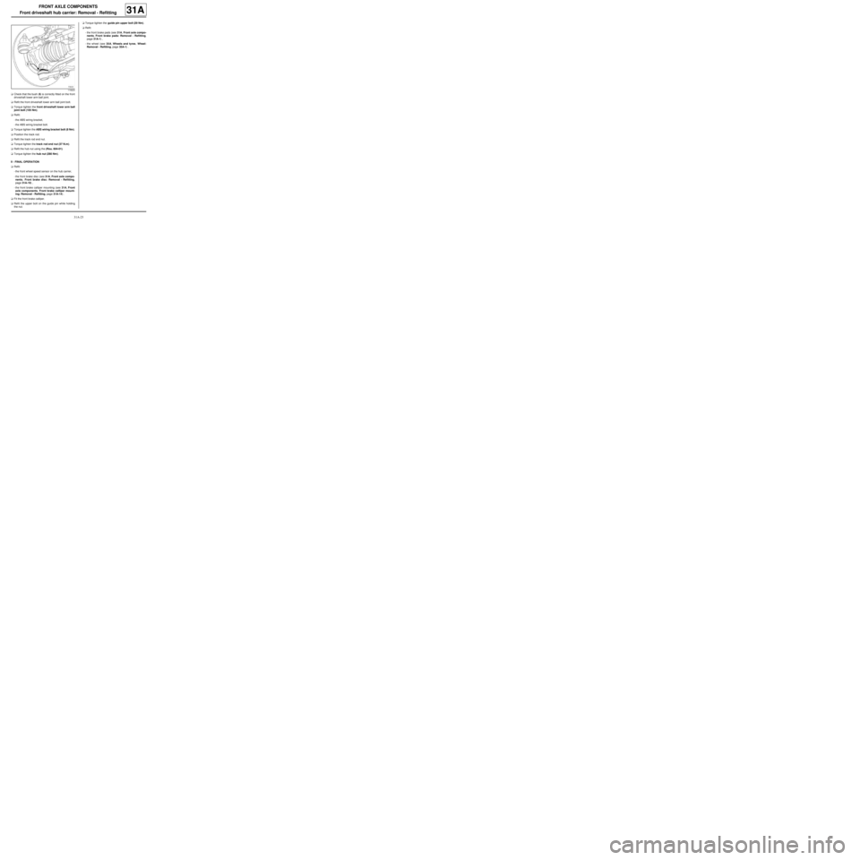
aCheck that the bush (6) is correctly fitted on the front
driveshaft lower arm ball joint.
aRefit the front driveshaft lower arm ball joint bolt.
aTorque tighten the front driveshaft lower arm ball
joint bolt (105 Nm).
aRefit:
-the ABS wiring bracket,
-the ABS wiring bracket bolt.
aTorque tighten the ABS wiring bracket bolt (8 Nm).
aPosition the track rod.
aRefit the track rod end nut.
aTorque tighten the track rod end nut (37 N.m).
aRefit the hub nut using the (Rou. 604-01).
aTorque tighten the hub nut (280 Nm).
II - FINAL OPERATION
aRefit:
-the front wheel speed sensor on the hub carrier,
-the front brake disc (see 31A, Front axle compo-
nents, Front brake disc: Removal - Refitting,
page 31A-19) ,
-the front brake calliper mounting (see 31A, Front
axle components, Front brake calliper mount-
ing: Removal - Refitting, page 31A-14) .
aFit the front brake calliper.
aRefit the upper bolt on the guide pin while holding
the nut.aTorque tighten the guide pin upper bolt (29 Nm).
aRefit:
-the front brake pads (see 31A, Front axle compo-
nents, Front brake pads: Removal - Refitting,
page 31A-1) ,
-the wheel (see 35A, Wheels and tyres, Wheel:
Removal - Refitting, page 35A-1) .
119223
Page 69 of 281
31A-26
FRONT AXLE COMPONENTS
Front hub carrier bearing: Removal - Refitting
31A
REMOVAL
I - REMOVAL PREPARATION OPERATION
aPosition the vehicle on a two-post lift ( (see Vehicle:
Towing and lifting) ).
aRemove:
-the front wheel on the side in question (see 35A,
Wheels and tyres, Wheel: Removal - Refitting,
page 35A-1) ,
-the front brake pads (see 31A, Front axle compo-
nents, Front brake pads: Removal - Refitting,
page 31A-1) ,
-the calliper mounting (see 31A, Front axle com-
ponents, Front brake calliper mounting: Re-
moval - Refitting, page 31A-14) ,
-the brake disc (see 31A, Front axle components,
Front brake disc: Removal - Refitting, page 31A-
19) ,
-the front driveshaft hub carrier (see 31A, Front
axle components, Front driveshaft hub carrier:
Removal - Refitting, page 31A-23) .II - OPERATION FOR REMOVAL OF PART
CONCERNED
aRemove:
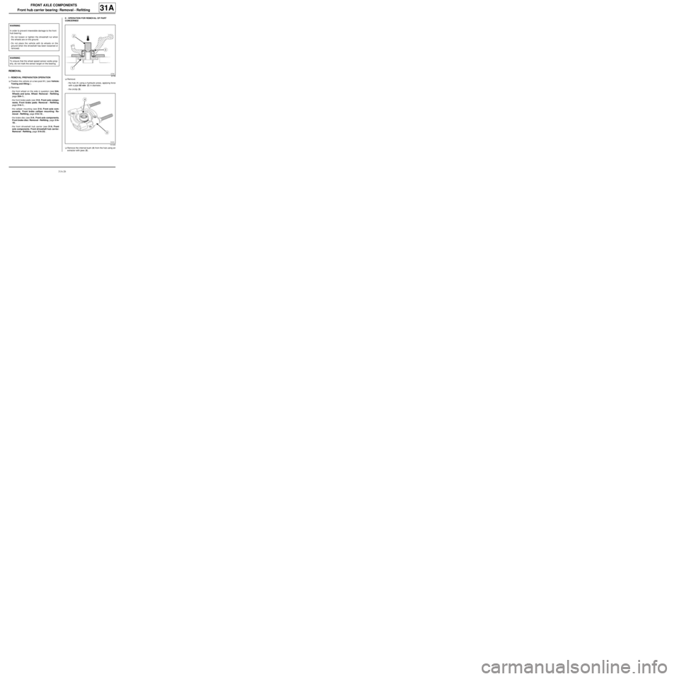
-the hub (1) using a hydraulic press, applying force
with a pipe 65 mm (2) in diameter,
-the circlip (3) .
aRemove the internal bush (4) from the hub using an
extractor with jaws (5) . WARNING
In order to prevent irreversible damage to the front
hub bear ing:
-Do not loosen or tighten the driveshaft nut when
the wheels are on the ground.
-Do not place the vehicle with its wheels on the
ground when the driveshaft has been loosened or
removed.
WARNING
To ensure that the wheel speed sensor works prop-
erly, do not mark the sensor target on the bearing.20786
101230
Page 133 of 281
33A-35
REAR AXLE COMPONENTS
Rear stub axle carrier: Removal - Refitting
EQ UIPMENT LEVEL SPORT
33A
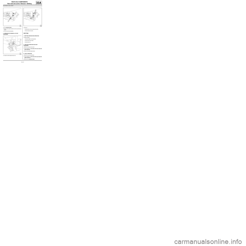
aFit a component jack.
aRemove the lower bolt (3) from the rear shock ab-
sorber.
aTip the rear shock absorber.
II - OPERATION FOR REMOVAL OF PART
CONCERNED
aUnclip the wheel speed sensor (4) .aRemove:
-the bolts (5) of the rear stub axle carrier,
-the rear stub axle carrier.
REFITTING
I - REFITTING PREPARATION OPERATION
aAlways replace:
-the brake calliper mounting bolts,
-the stub axle carrier bolts,
-the stub-axle nut.
II - REFITTING OPERATION FOR PART
CONCERNED
aRefit the rear stub axle carrier.
aTorque tighten the new bolts of the rear stub axle
carrier (53 N.m).
aClip on the wheel speed sensor.
III - FINAL OPERATION.
aRefit the rear shock absorber.
aTorque tighten the lower bolt of the rear shock ab-
sorber (105 N.m).
aRemove the component jack.
132462
132463132462
Page 136 of 281
33A-38
REAR AXLE COMPONENTS
Complete rear axle system: Removal - Refitting
33A
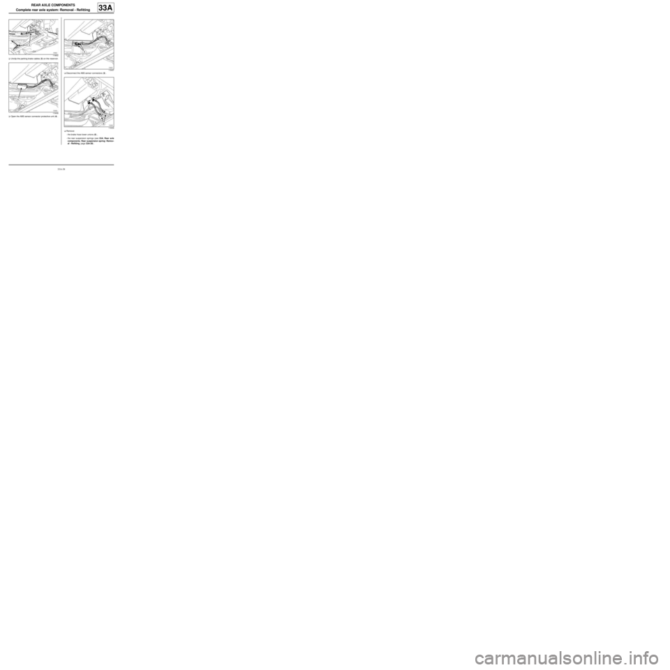
aUnclip the parking brake cables (3) on the reservoir.
aOpen the ABS sensor connector protective unit (4) .aDisconnect the ABS sensor connectors (5) .
aRemove:
-the brake hose lower unions (6) ,
-the rear suspension springs (see 33A, Rear axle
components, Rear suspension spring: Remov-
al - Refitting, page 33A-28) .
119652
119438
119437
119339
Page 139 of 281
33A-41
REAR AXLE COMPONENTS
Complete rear axle system: Removal - Refitting
33A
aUnclip the end of the parking brake cables at (10) .
aUnclip the cable sleeve stops at (11) and extract the
parking brake cables from the rear drum flanges.
aRemove:
-the rear brake pads (see 33A, Rear axle compo-
nents, Rear brake lining: Removal - Refitting,
page 33A-14) ,
-the rear brake cylinders (see 33A, Rear axle com-
ponents, Rear brake cylinder: Removal - Refit-
ting, page 33A-17) ,
-the rear wheel speed sensors (see 38C, Anti-lock
braking system, Rear wheel speed sensor: Re-
moval - Refitting, page 38C-17) ,
-the rear rigid brake pipes from the rear axle,
-the rear rigid brake pipe clips from the rear axle,
-the rear stub axle carriers (see 33A, Rear axle
components, Rear stub axle carrier: Removal -
Refitting, page 33A-32) ,
-the rear brake drum flanges,
REFITTING
I - REFITTING PREPARATIONS OPERATION
aStrap the rear axle onto the (Mot. 1390).
aPosition the rear axle under the vehicle.II - REFITTING OPERATION FOR PART
CONCERNED
1 - Replacement
aRefit:
-the rear brake drum flanges,
-the rear stub axle carriers (see 33A, Rear axle
components, Rear stub axle carrier: Removal -
Refitting, page 33A-32) ,
-the rigid brake pipe clips on the rear axle,
-the rear rigid brake pipes from the rear axle,
-the rear wheel speed sensors (see 38C, Anti-lock
braking system, Rear wheel speed sensor: Re-
moval - Refitting, page 38C-17) ,
-the rear brake cylinders (see 33A, Rear axle com-
ponents, Rear brake cylinder: Removal - Refit-
ting, page 33A-17) ,
-the rear brake pads (see 33A, Rear axle compo-
nents, Rear brake lining: Removal - Refitting,
page 33A-14) .
-the parking brake cables (see 37A, Mechanical
component controls, Parking brake cables: Re-
moval - Refitting, page 37A-74) ,
-the rear brake drums (see 33A, Rear axle compo-
nents, Rear brake drum: Removal - Refitting,
page 33A-19) .
121331
Page 140 of 281

33A-42
REAR AXLE COMPONENTS
Complete rear axle system: Removal - Refitting
33A
2 - Refitting
aLower the lift.
aPosition the bearing centring devices (12) opposite
the centring holes.
aRefit the rear axle bearing bolts.
aTorque tighten the rear axle bearing bolts (62 Nm).
aRemove the safety strap(s).
aRaise the lift.
aRefit:
-the rear suspension springs (see 33A, Rear axle
components, Rear suspension spring: Remov-
al - Refitting, page 33A-28) ,
-the brake hose lower unions.
aTorque tighten the brake hose lower unions (17
Nm).
aConnect the ABS sensor connectors.
aClose the ABS sensor connector protective unit.
aClip the parking brake cables onto the reservoir.
aPosition the parking brake cables on the parking
brake compensator.
aCheck that the parking brake cable stops are proper-ly inserted in their housings.
III - FINAL OPERATION.
aAdjust the parking brake cables (see 37A, Mechan-
ical component controls, Parking brake lever:
Removal - Refitting, page 37A-46) .
aRefit the rear wheels (see 35A, Wheels and tyres,
Wheel: Removal - Refitting, page 35A-1) .
aRemove the pedal press.
aBleed the braking circuit (see 30A, General infor-
mation, Braking circuit: Bleed, page 30A-4) .
119651
Page 180 of 281
37A-1
MECHANICAL COMPONENT CONTROLS
Master cylinder: Removal - Refitting
JB1 or JH1 or JH3 or JR5
37A
REMOVAL
I - REMOVAL PREPARATION OPERATION
aPosition the vehicle on a two-post lift (see Vehicle:
Towing and lifting) (02A, Lifting equipment).
aRemove:
-the battery (see Battery: Removal - Refitting)
(80A, Battery)
-the battery tray (see Battery tray: Removal - Re-
fitting) (80A, Battery).
aRemove:
-the injection computer (see Petrol injection com-
puter: Removal - Refitting) (17B, Petrol injection),
-the injection computer support.II - OPERATION FOR REMOVAL OF PART
CONCERNED
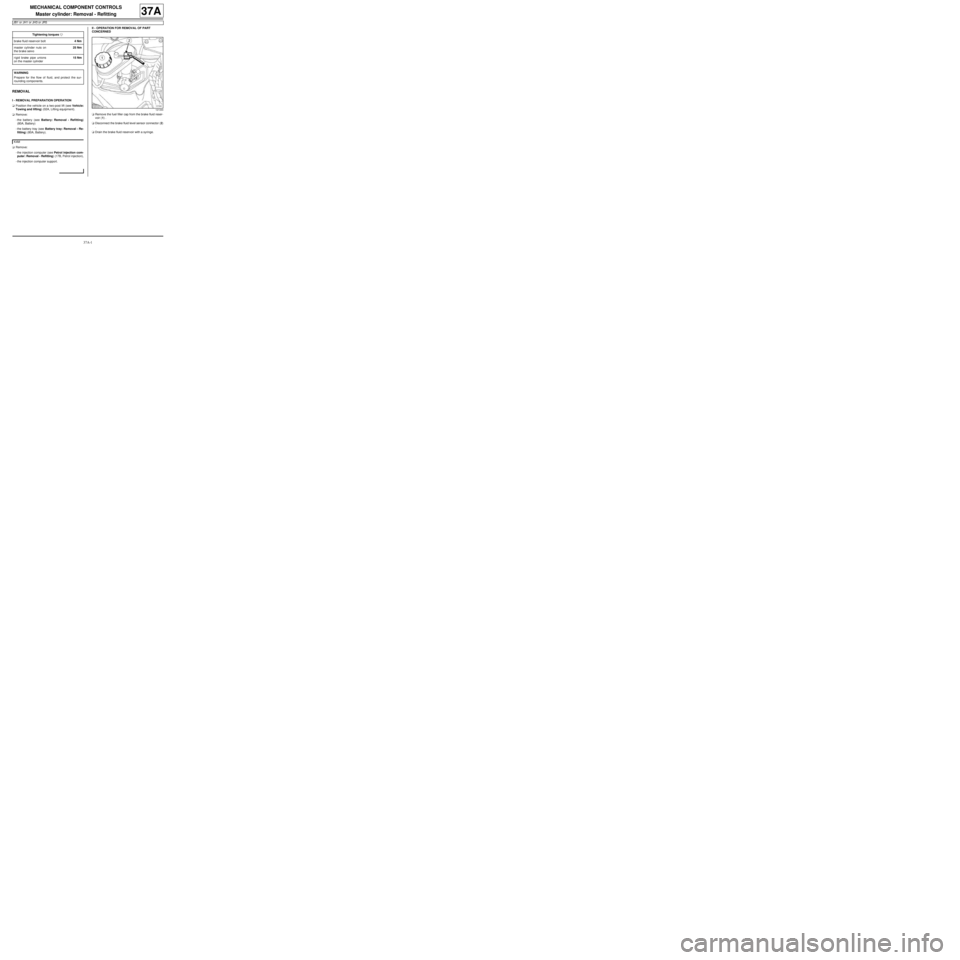
aRemove the fuel filler cap from the brake fluid reser-
voir (1) .
aDisconnect the brake fluid level sensor connector (2)
.
aDrain the brake fluid reservoir with a syringe. Tightening torquesm
brake fluid reservoir bolt4 Nm
master cylinder nuts on
the brake servo25 Nm
rigid brake pipe unions
on the master cylinder15 Nm
WARNING
Prepare for the flow of fluid, and protect the sur-
rounding components.
K4M
121344
Page 182 of 281
37A-3
MECHANICAL COMPONENT CONTROLS
Master cylinder: Removal - Refitting
JB1 or JH1 or JH3 or JR5
37A
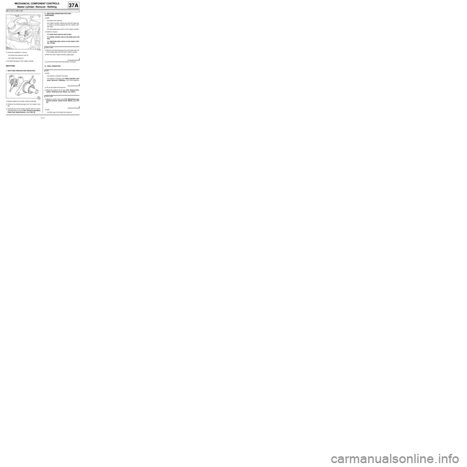
aUsing the workbench, remove:
-the brake fluid reservoir bolt (7) ,
-the brake fluid reservoir.
aFit blanking plugs on the master cylinder.
REFITTING
I - REFITTING PREPARATION OPERATION
aAlways replace the master cylinder seals (8) .
aRemove the blanking plugs from the master cylin-
der.
aCarefully pre-fill the master cylinder with the recom-
mended brake fluid (see 30A, General information,
Brake fluid: Specifications, page 30A-18) .II - REFITTING OPERATION FOR PART
CONCERNED
aRefit:
-the brake fluid reservoir,
-the master cylinder making sure that the brake ser-
vo shaft is correctly aligned with the master cylin-
der shaft,
-the rigid brake pipe unions on the master cylinder.
aTighten to torque:
-the brake fluid reservoir bolt (4 Nm),
-the master cylinder nuts on the brake servo (25
Nm),
-the rigid brake pipe unions on the master cylin-
der (15 Nm).
aRemove the blanking plugs from the brake fluid res-
ervoir supply pipe and the clutch master cylinder.
aRefit the clutch master cylinder supply pipe.
aConnect the brake fluid level sensor connector.
III - FINAL OPERATION.
aRefit:
-the injection computer mounting,
-the injection computer (see Petrol injection com-
puter: Removal - Refitting) (17B, Petrol injection).
aFill up the brake fluid reservoir.
aBleed the braking circuit (see 30A, General infor-
mation, Braking circuit: Bleed, page 30A-4) .
aBleed the clutch circuit (see 37A, Mechanical com-
ponent controls, Clutch circuit: Bleed, page 37A-
54) .
aRefit:
-the filler cap of the brake fluid reservoir.
121345
112622
JH3 or JR5
K4M
JH3 or JR5