clock RENAULT TWINGO RS 2009 2.G Chasiss Workshop Manual
[x] Cancel search | Manufacturer: RENAULT, Model Year: 2009, Model line: TWINGO RS, Model: RENAULT TWINGO RS 2009 2.GPages: 281
Page 153 of 281
36A-2
STEERING ASSEMBLY
Track rod: Removal - Refitting
36A
REMOVAL
I - REMOVAL PREPARATION OPERATION
aPosition the vehicle on a two-post lift (see Vehicle:
Towing and lifting) (02A, Lifting equipment).
aRemove the front wheel (see 35A, Wheels and ty-
res, Wheel: Removal - Refitting, page 35A-1) .
II - OPERATION FOR REMOVAL OF PART
CONCERNED
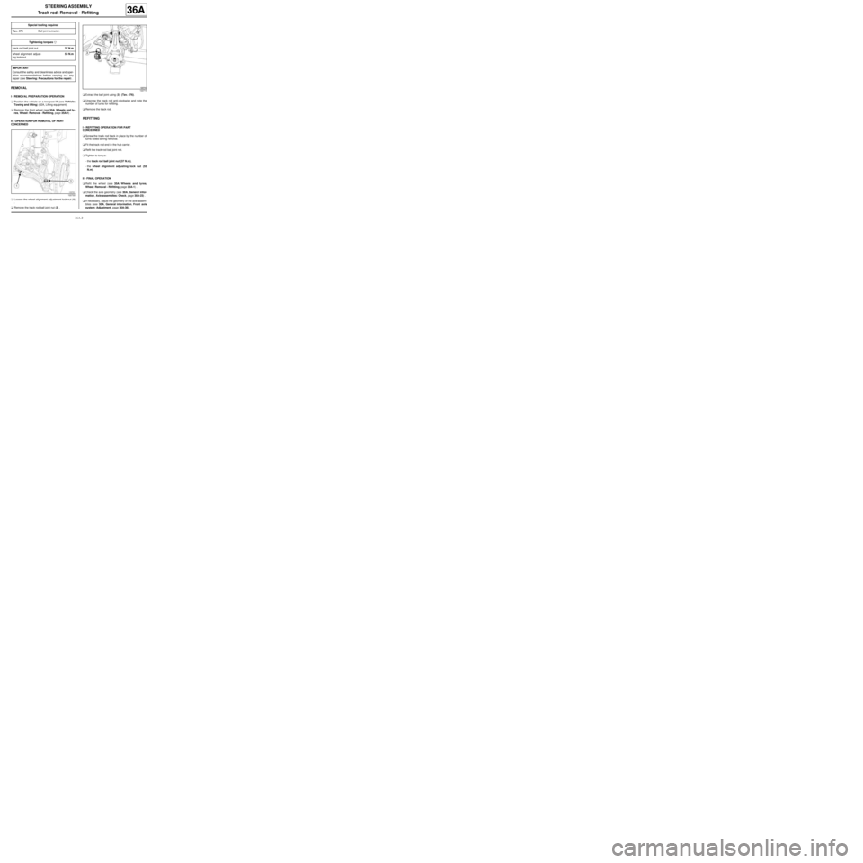
aLoosen the wheel alignment adjustment lock nut (1)
.
aRemove the track rod ball joint nut (2) .aExtract the ball joint using (3) (Tav. 476).
aUnscrew the track rod anti-clockwise and note the
number of turns for refitting.
aRemove the track rod.
REFITTING
I - REFITTING OPERATION FOR PART
CONCERNED
aScrew the track rod back in place by the number of
turns noted during removal.
aFit the track rod end in the hub carrier.
aRefit the track rod ball joint nut.
aTighten to torque:
-the track rod ball joint nut (37 N.m),
-the wheel alignment adjusting lock nut (53
N.m).
II - FINAL OPERATION
aRefit the wheel (see 35A, Wheels and tyres,
Wheel: Removal - Refitting, page 35A-1) .
aCheck the axle geometry (see 30A, General infor-
mation, Axle assemblies: Check, page 30A-23) .
aIf necessary, adjust the geometry of the axle assem-
blies (see 30A, General information, Front axle
system: Adjustment, page 30A-36) . Special tooling required
Tav. 476Ball joint extractor.
Tightening torquesm
track rod ball joint nut37 N.m
wheel alignment adjust-
ing lock nut53 N.m
IMPORTANT
Consult the safety and cleanliness advice and oper-
ation recommendations before carrying out any
repair (see Steering: Precautions for the repair) .
122722
122713
Page 221 of 281
37A-42
MECHANICAL COMPONENT CONTROLS
Brake pedal switch: Removal - Refitting
37A
REMOVAL
I - REMOVAL PREPARATION OPERATION
aRemove:
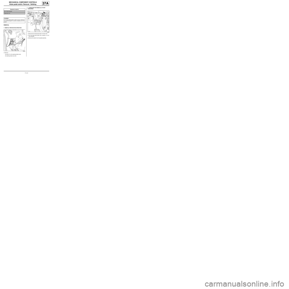
-the bolts (1) of the steering wheel cover,
-the steering wheel cover (2) .II - OPERATION FOR REMOVAL OF PART
CONCERNED
aDisconnect the brake light switch connector (3) .
aTurn the brake light switch (4) a quarter of a turn
anti-clockwise.
aRemove the switch from the pedal assembly. Equipment required
set of feeler gauges
Diagnostic tool
WARNING
The brake pedal position switch must be replaced if
the notched segment is pulled completely out of the
switch.
120279
121350
Page 223 of 281
37A-44
MECHANICAL COMPONENT CONTROLS
Brake pedal switch: Removal - Refitting
37A
aTake a set of feeler gauges
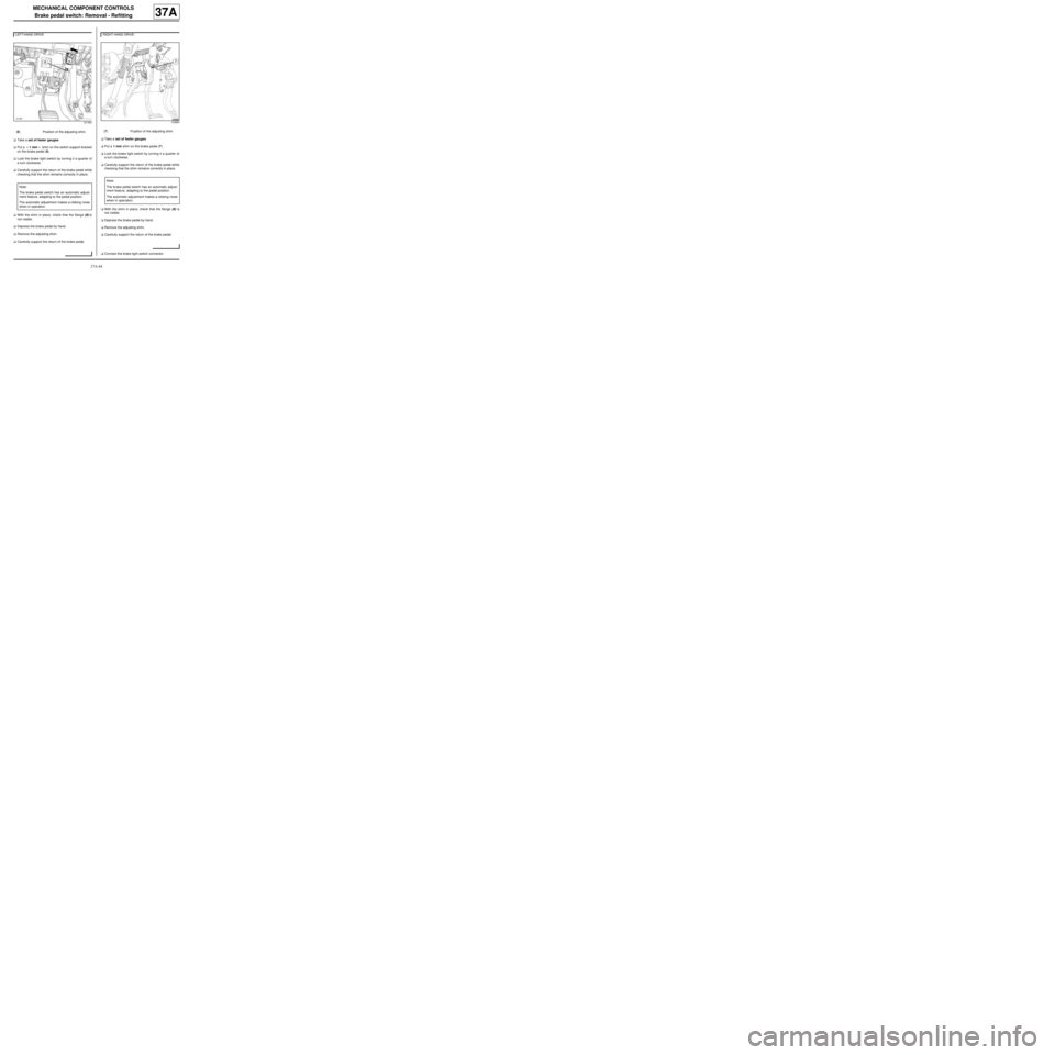
aPut a « 1 mm » shim on the switch support bracket
on the brake pedal (6) .
aLock the brake light switch by turning it a quarter of
a turn clockwise.
aCarefully support the return of the brake pedal while
checking that the shim remains correctly in place.
aWith the shim in place, check that the flange (8) is
not visible.
aDepress the brake pedal by hand.
aRemove the adjusting shim.
aCarefully support the return of the brake pedal.aTake a set of feeler gauges
aPut a 1 mm shim on the brake pedal (7) .
aLock the brake light switch by turning it a quarter of
a turn clockwise.
aCarefully support the return of the brake pedal while
checking that the shim remains correctly in place.
aWith the shim in place, check that the flange (8) is
not visible.
aDepress the brake pedal by hand.
aRemove the adjusting shim.
aCarefully support the return of the brake pedal.
aConnect the brake light switch connector. LEFT-HAND DRIVE
121350
(6) Position of the adjusting shim.
Note:
The brake pedal switch has an automatic adjust-
ment feature, adapting to the pedal position.
The automatic adjustment makes a clicking noise
when in operation.
RIGHT-HAND DRIVE
123860
(7) Position of the adjusting shim.
Note:
The br ake pedal switch has an automatic adjust-
ment feature, adapting to the pedal position.
The automatic adjustment makes a clicking noise
when in oper ation.
Page 231 of 281
37A-52
MECHANICAL COMPONENT CONTROLS
Clutch pedal switch: Removal - Refitting
CRUISE CONTROL, and 5-SPEED MANUAL GEARBOX
37A
REMOVAL
I - REMOVAL PREPARATION OPERATION
aRemove the dashboard glovebox.
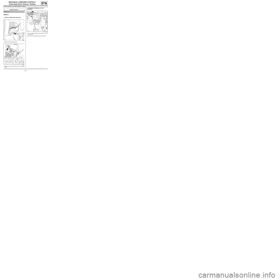
aDisconnect the connector (2) from the clutch pedal
switch.II - OPERATION FOR REMOVAL OF PART
CONCERNED
aTurn the clutch pedal switch (3) a quarter of a turn
anti-clockwise
aRemove the clutch pedal switch from the pedal. Equipment required
Diagnostic tool
119506
119507
121349
Page 232 of 281
37A-53
MECHANICAL COMPONENT CONTROLS
Clutch pedal switch: Removal - Refitting
CRUISE CONTROL, and 5-SPEED MANUAL GEARBOX
37A
REFITTING
I - REFITTING PREPARATIONS OPERATION
a
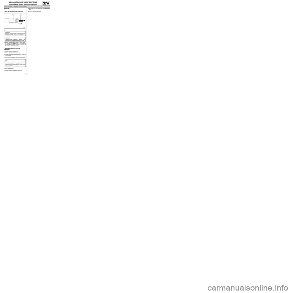
aMeasure dimension of the piston (4) . If the dimen-
sion (x) is less than 15 mm, carefully pull the end of
the piston (4) to adjust the dimension to between 15
mm minimum and 17 mm maximum.
II - REFITTING OPERATION FOR PART
CONCERNED
aDepress the clutch pedal by hand.
aFit the clutch pedal switch to the pedal.
aLock the clutch pedal switch by turning it a quarter of
a turn clockwise.
aAt the same time, carefully return the clutch pedal.
III - FINAL OPERATION.
aConnect the clutch pedal switch connector.aBe sure to carry out a repair check using Diagnostic
tool.
aRefit the dashboard glovebox.
108436
WARNING
Whenever the clutch pedal switch piston is com-
pletely removed, the switch must be replaced.
WARNING
The switch must be replaced if handling of the
piston results in three adjustments being made.
Note:
The clutch pedal switch has an automatic adjust-
ment feature, adapting to the pedal position.
The automatic adjustment makes a clicking noise
when in operation.