engine coolant RENAULT TWINGO RS 2009 2.G Electrical Equipment - Petrol Injection User Guide
[x] Cancel search | Manufacturer: RENAULT, Model Year: 2009, Model line: TWINGO RS, Model: RENAULT TWINGO RS 2009 2.GPages: 348
Page 31 of 348
17B-31V7 MR-413-X44-17B000$070.mif
PETROL INJECTION
Fault finding – Role of components17B
SIM 32 Injection
Program no.: D3
Vdiag No.: 44, 4C, 50
and 54
TDC sensor:
The angular position is measured using a magneto-inductive sensor triggered by the machined teeth on the engine
flywheel. This sensor gives the engine speed as well as the position of the crankshaft for injection.
Refrigerant pressure sensor:
Its role is to measure the refrigerant pressure in the air conditioning circuit.
Engine coolant temperature sensor:
The engine coolant temperature sensor informs the computer of the engine coolant temperature.
Air temperature sensor:
The air temperature sensor is fitted inside the inlet manifold and informs the computer of the temperature of the air
taken in by the engine.
Catalytic converter:
The role of the catalytic converter is to convert pollutant gases into harmless gases.
Cruise control/speed limiter on/off switch:
This switch is used to turn the cruise control/speed limiter on or off.
Fan unit relay:
This relay actuates the motor-driven fan assemblies when a temperature threshold has been exceeded.
Accelerator potentiometer:
The accelerator potentiometer informs the computer of the position of the accelerator pedal (engine load).
Clutch pedal switch:
The clutch pedal switch informs the computer of the clutch pedal status.
Inlet air temperature sensor:
Its role is to measure the air temperature in the inlet circuit.
Pinking sensor:
Its role is to check for pinking in the combustion chamber.
Oil level sensor:
This sensor measures the level of oil in the engine and sends this information to the computer.
Page 35 of 348
17B-35V7 MR-413-X44-17B000$090.mif
17B
SIM 32 Injection
Program no.: D3
Vdiag No.: 44, 4C, 50
and 54
1. COMPUTER REPLACEMENT OR REPROGRAMMING OPERATIONS
Computer replacement or reprogramming for engines with the OCS (customised oil change interval)
function.
For Vdiag 44 and 4C, commands SC001 and SC003 are not accessible.
The system can be programmed via the diagnostic socket using the RENAULT CLIP diagnostic tool (refer to
Technical Note 3585A, COMPUTER PROGRAMMING AND REPROGRAMMING PROCEDURE or follow the
instructions given by the diagnostic tool). Only in Vdiag 54 and certain engines in Vdiag 50:
For Vdiag 50, the procedure below should be followed only if ET840 Customised Oil Change Interval is ACTIVE.
Certain variables linked to the O.C.S and the details of the last four oil services are saved by the computer.
However, all data saved is cleared during a reprogramming operation. When replacing or reprogramming the
computer, it is necessary to save the data from the old computer so it can be written to the new computer
(or reprogrammed). To do this before changing (or reprogramming) the computer, it is necessary to run the request
SC003 Save computer data, and after it has been changed (or reprogrammed), it is necessary to run the request
SC001 Write saved data.
For Vdiag 50, if ET840 Customised Oil Change Interval is INACTIVE, commands SC001 and SC003 should
not be used.
Operations to check before reprogramming the injection computer:
Before reprogramming the injection computer, move the main Cruise control/Speed limiter switch to the rest
position. The information about the cruise control or the speed limiter displayed on the instrument panel
disappears.
Otherwise, if the main switch remains in the cruise control or speed limiter position during and after reprogramming,
the Cruise control/Speed limiter function will not be operational.
The procedure for resetting the function is as follows:
Ignition switched on and main switch in rest position (the computer detects rest position at that moment).
Switch in Cruise control position to activate the Cruise control function.
Switch in Speed limiter position to activate the Speed limiter function.
IMPORTANT:
–Switch on the diagnostic tool (mains or cigarette lighter supply).
–Connect a battery charger.
–Switch off all electrical consumers (lights, interior lighting, air conditioning, radio, etc.).
–Wait for the engine to cool (engine coolant temperature below 60˚C and air temperature below 50˚C).
PETROL INJECTION
Fault finding – Replacement of components
Page 39 of 348
17B-39V7 MR-413-X44-17B000$110.mif
17B
SIM 32 Injection
Program no.: D3
Vdiag No.: 44, 4C, 50
and 54
2. PROGRAMMING
Flywheel target programming
(To be carried out when replacing or removing the TDC sensor).
The coolant temperature must be over 35˚C.
–Carry out an initial deceleration with injection cut-off (feet off the brake, accelerator and clutch pedals) between
3500 and 3000 rpm, in 3rd gear for at least 5 seconds for manual gearboxes.
–Decelerate a second time with injection cut-off (feet off the brake, accelerator and clutch pedals) between 2400 and
2000 rpm, in 3rd gear for at least 5 seconds for manual gearboxes.
Check the programming with ET089 Programming flywheel target: Performed.
Programming the throttle end stops
After replacement of the computer or the motorised throttle valve, with the ignition on, wait 30 seconds so that the
computer can program the Upper and Lower limits and then switch off the ignition and wait 30 seconds for the end of
the "Power Latch", so that the computer can store the programmed limits. Check the programming with ET051
Programming throttle stops: Performed.
Programming the alcohol level (only for vehicles running on Ethanol or E85 fuel)
Fuel recognition is carried out by observing the drift of the richness controller.
This can only be performed if the mixture regulation is looped (ET300 Mixture regulation).
Programming procedure:
–start the engine,
–wait for the engine coolant temperature to reach 75˚C and then check using the parameter PR064 "Coolant
temperature",
–run the engine at 1500 rpm for a period of at least 5 minutes,
–check that the programming has been carried out using status ET671 Alcohol level programming and
parameter PR743 Estimated alcohol level in tank,
–the programming is saved when the ignition is switched off. Note:
After replacement of the throttle valve run the command RZ005 Programming to erase any recorded
programming.
Note:
When the injection computer has not recognised the fuel composition, operation is faulty.
PETROL INJECTION
Fault finding – Programming
Page 42 of 348
17B-42V7 MR-413-X44-17B000$120.mif
PETROL INJECTION
Fault finding – Fault summary table17B
SIM 32 Injection
Program no.: D3
Vdiag No.: 44, 4C, 50
and 54
* TA: Automatic Transmission
* RV/LV: Cruise control/Speed limiter function
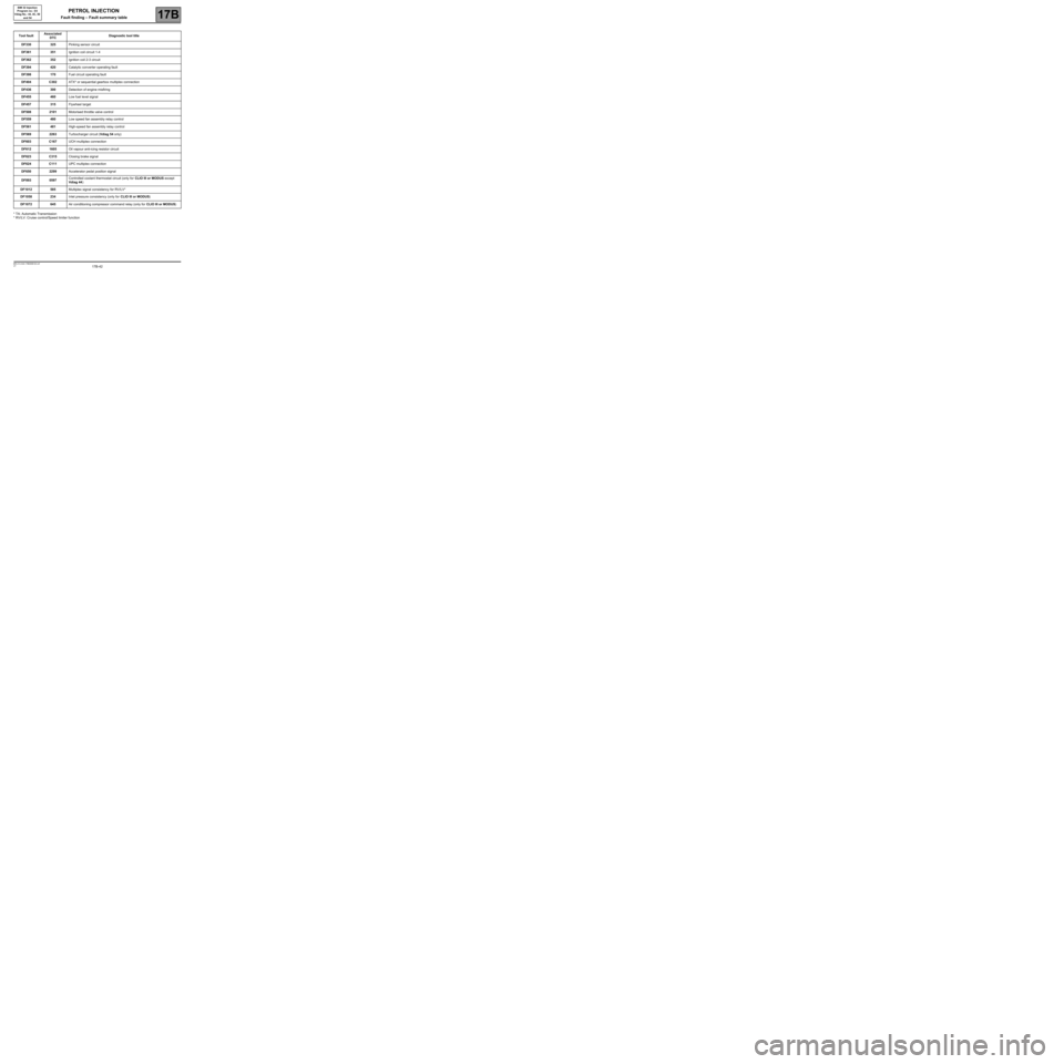
Tool faultAssociated
DTCDiagnostic tool title
DF330325Pinking sensor circuit
DF361351Ignition coil circuit 1-4
DF362352Ignition coil 2-3 circuit
DF394420Catalytic converter operating fault
DF398170Fuel circuit operating fault
DF404C302ATX* or sequential gearbox multiplex connection
DF436300Detection of engine misfiring
DF455460Low fuel level signal
DF457315Flywheel target
DF5082101Motorised throttle valve control
DF559480Low speed fan assembly relay control
DF561481High-speed fan assembly relay control
DF5692263Turbocharger circuit (Vdiag 54 only)
DF603C167UCH multiplex connection
DF6121605Oil vapour anti-icing resistor circuit
DF623C315Closing brake signal
DF624C111UPC multiplex connection
DF6502299Accelerator pedal position signal
DF8930597Controlled coolant thermostat circuit (only for CLIO III or MODUS except
Vdiag 44)
DF1012585Multiplex signal consistency for RV/LV*
DF1058234Inlet pressure consistency (only for CLIO III or MODUS)
DF1072645Air conditioning compressor command relay (only for CLIO III or MODUS)
Page 43 of 348
17B-43V7 MR-413-X44-17B000$131.mif
17B
SIM 32 Injection
Program no.: D3
Vdiag No.: 44, 4C, 50
and 54
* EOBD: European On Board Diagnostics
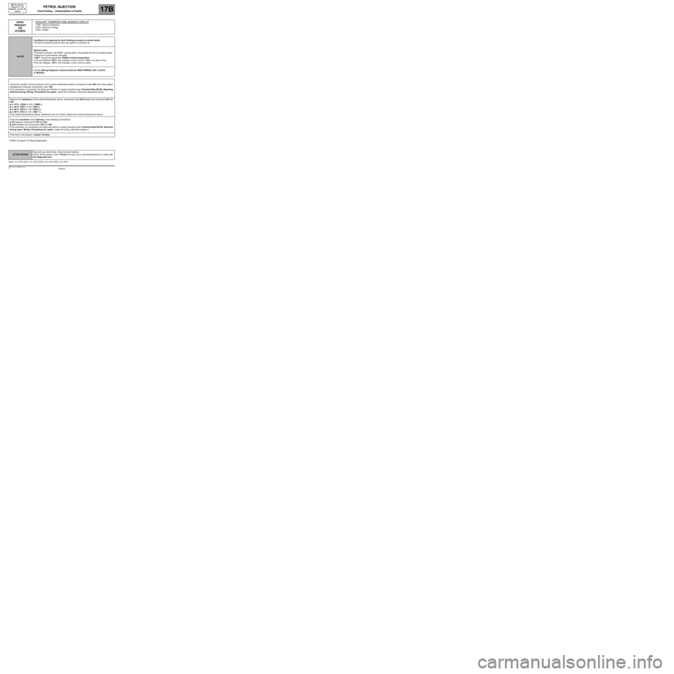
DF001
PRESENT
OR
STOREDCOOLANT TEMPERATURE SENSOR CIRCUIT
1.DEF: signal incoherence
2.DEF: abnormal voltage
3.DEF: EOBD*
NOTESConditions for applying the fault finding procedure to stored faults:
The fault is declared present when the ignition is switched on.
Special notes:
If the fault is present, the EOBD* warning light is illuminated and the low speed engine
cooling fan is permanently activated.
1.DEF: Consult the parameter PR064 Coolant temperature:
If the tool displays 120˚C, this indicates a short circuit to 12V or an open circuit.
If the tool displays - 40˚C, this indicates a short circuit to earth.
Use the Wiring Diagrams Technical Note for NEW TWINGO, E33, CLIO III,
or MODUS.
Check the condition of the connector of the coolant temperature sensor (component code 244) and of the engine
management computer (component code 120).
If the connector or connectors are faulty and if there is a repair procedure (see Technical Note 6015A, Repairing
electrical wiring, Wiring: Precautions for repair), repair the connector, otherwise replace the wiring.
Measure the resistance of the coolant temperature sensor, component code 244 between the connections 3C and
3JK:
●at 10˚C: 12030 Ω < X < 12890 Ω,
●at 25˚C: 2195 Ω < X < 2309 Ω,
●at 50˚C: 795.5 Ω < X < 826.5 Ω,
●at 80˚C: 279.3 Ω < X < 286.7 Ω.
If the coolant temperature sensor resistances are not correct, replace the coolant temperature sensor.
Check the insulation and continuity of the following connections:
●3C between components 120 and 244,
●3JK between the components 120 and 244.
If the connection or connections are faulty and there is a repair procedure (see Technical Note 6015A, Electrical
wiring repair, Wiring: Precautions for repair), repair the wiring, otherwise replace it.
If the fault is still present, contact Techline.
SIM32_V44_DF001/SIM32_V4C_DF001/SIM32_V50_DF001/SIM32_V54_DF001
PETROL INJECTION
Fault finding – Interpretation of faults
AFTER REPAIRDeal with any other faults. Clear the fault memory.
Switch off the ignition, wait 1 minute and carry out a road test followed by a check with
the diagnostic tool.
Page 134 of 348
17B-134V7 MR-413-X44-17B000$133.mif
PETROL INJECTION
Fault finding – Interpretation of faults17B
SIM 32 Injection
Program no.: D3
Vdiag No.: 44, 4C, 50
and 54
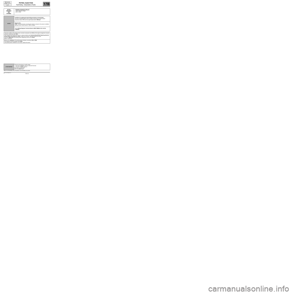
DF330
PRESENT
OR
STOREDPINKING SENSOR CIRCUIT
1.DEF: Abnormal voltage
2.DEF: EOBD
NOTESConditions for applying the fault finding procedure to stored faults:
The fault is declared present with the engine running with an engine coolant
temperature above 75˚C and the engine speed above 1500 rpm.
Special notes:
1.DEF: The wiring harness connecting the injection computer to the sensor is shielded.
Because of this, a short circuit to + 12 V is unlikely.
Use the Wiring Diagrams Technical Note for NEW TWINGO, E33, CLIO III,
or MODUS.
Check the condition of the pinking sensor connector (component code 146) and the engine management computer
connector (component code 120).
If the connectors are faulty and if there is a repair procedure (see Technical Note 6015A, Repairing electrical
wiring, Wiring: Precautions for repair), repair the connector, otherwise replace the wiring.
Check the tightening of the pinking sensor (tightening must be: X = 20 Nm).
Repair if necessary.
Measure the resistance of the pinking sensor between connections 3S and 3DQ:
The resistance should be greater than 20 MΩ.
If the pinking sensor resistance is not correct, replace the sensor.
SIM32_V44_DF330/SIM32_V4C_DF330/SIM32_V50_DF330/SIM32_V54_DF330
AFTER REPAIRFollow the instructions to confirm repair:
–If the fault is present, continue to deal with the fault.
–If the fault is stored, ignore it.
Deal with any other faults.
Clear the stored faults.
Page 142 of 348
17B-142V7 MR-413-X44-17B000$133.mif
PETROL INJECTION
Fault finding – Interpretation of faults17B
SIM 32 Injection
Program no.: D3
Vdiag No.: 44, 4C, 50
and 54
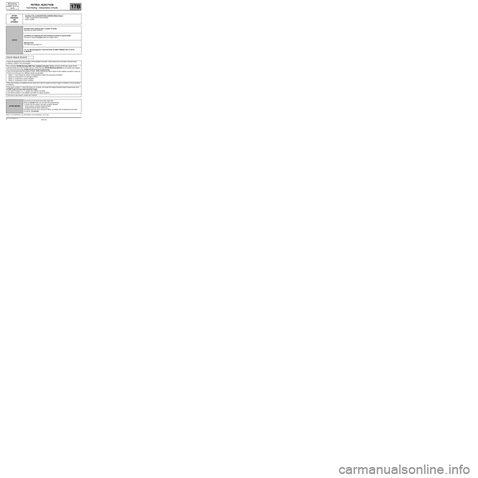
DF394
PRESENT
OR
STOREDCATALYTIC CONVERTER OPERATING FAULT
1.DEF: Component in bad condition
2.DEF: EOBD
NOTESPriorities when dealing with a number of faults:
Deal with any other fault first.
Conditions for applying the fault finding procedure to stored faults:
The fault is declared present after the engine starts.
Special notes:
The OBD warning light is lit.
Use the Wiring Diagrams Technical Note for NEW TWINGO, E33, CLIO III,
or MODUS.
Only for Vdiag 4C, 50 and 54
Check the appearance and condition of the catalytic converter. Check there are no air leaks, thermal shock,
misfiring, coolant or oil consumption.
Run command SC006 Running OBD Test: catalytic converter. Before carrying out this test, repair all the
electrical faults and clear the fault memory. Check that fault DF436 Misfiring detection is not present and program
the engine flywheel target ET089 Flywheel target programming.
Carry out this test when the engine is warm, which reduces the time it takes for the catalytic converter to heat up.
At the end of this test, four different results are possible:
–Status 1: Fault finding not carried out/impossible to obtain the necessary conditions.
–Status 2: Component in an average condition.
–Status 3: Component in good condition.
–Status 4: Component in poor condition.
When fault finding is completed and the result read, stop the engine and start it again to establish normal operating
conditions.
If the result is status 1: check that there are no faults, and check the engine flywheel target programming using
ET089 Programming engine flywheel target.
If the result is status 2 or 4: replace the catalytic converter.
If the result is status 3: the catalytic converter is in good condition.
If the fault is still present, contact the Techline.
SIM32_V44_DF394/SIM32_V4C_DF394/SIM32_V50_DF394/SIM32_V54_DF394
AFTER REPAIREnsure that all the faults have been dealt with.
Clear the stored faults. Do not clear the programming.
To check that the system has been properly repaired:
–there must be no further electrical faults,
–programming has been carried out,
the engine must be warm (minimum 75˚C), and idling, with all electrical consumers
running for 15 minutes.
Page 143 of 348
17B-143V7 MR-413-X44-17B000$133.mif
PETROL INJECTION
Fault finding – Interpretation of faults17B
SIM 32 Injection
Program no.: D3
Vdiag No.: 44, 4C, 50
and 54
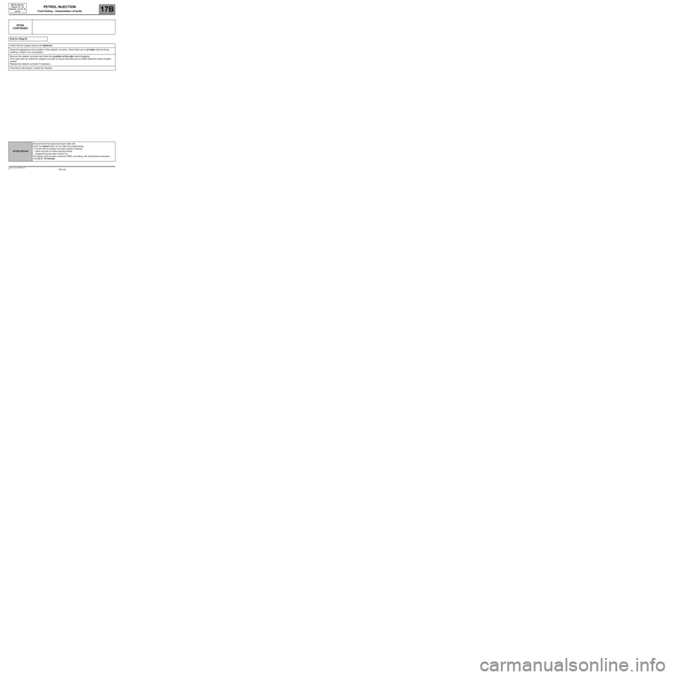
DF394
CONTINUED
Only for Vdiag 44
Check that the oxygen sensors are tightened.
Check the appearance and condition of the catalytic converter. Check there are no air leaks, thermal shock,
misfiring, coolant or oil consumption.
Remove the catalytic converter and check the condition of the cake inside (clogging).
If the cake looks ok, shake the catalytic converter to ensure that there are no broken elements inside (metallic
noises).
Replace the catalytic converter if necessary.
If the fault is still present, contact the Techline.
AFTER REPAIREnsure that all the faults have been dealt with.
Clear the stored faults. Do not clear the programming.
To check that the system has been properly repaired:
–there must be no further electrical faults,
–programming has been carried out,
the engine must be warm (minimum 75˚C), and idling, with all electrical consumers
running for 15 minutes.
Page 153 of 348
17B-153V7 MR-413-X44-17B000$133.mif
PETROL INJECTION
Fault finding – Interpretation of faults17B
SIM 32 Injection
Program no.: D3
Vdiag No.: 44, 4C, 50
and 54
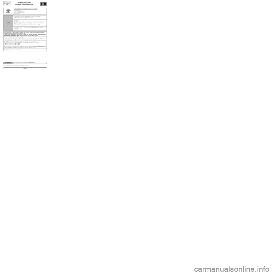
DF561
PRESENT
OR
STOREDHIGH-SPEED FAN ASSEMBLY RELAY CONTROLCO: Open circuit
CC.0: Short circuit to earth
CC.1: Short circuit to + 12 V
1.DEF: EOBD
NOTESConditions for applying the fault finding procedure to stored faults
The fault is declared present with the engine running.
Special note:
CO or CC.1: High speed fan assembly not activated, risk of engine overheating (the
coolant warning light should warn of overheating), risk of loss of air conditioning.
CC.0: High-speed fan assembly permanently activated.
The customer complains of slight overconsumption and noise in CC.0.
Use the Wiring Diagrams Technical Note for NEW TWINGO, E33, CLIO III,
or MODUS.
Check the condition of the high-speed fan assembly relay connector (component code 234) and the engine
management computer connector (component code 120).
If the connectors are faulty and if there is a repair procedure (see Technical Note 6015A, Repairing electrical
wiring, Wiring: Precautions for repair), repair the connector, otherwise replace the wiring.
Run command AC153 High speed fan assembly.
If the command does not work, with the ignition on, check for + 12 V on connection 3FB of the high-speed fan
assembly relay and the earthing of connection 3JP on the injection computer connector.
If the connection or connections are faulty and there is a repair procedure (see Technical Note 6015A, Electrical
wiring repair, Wiring: Precautions for repair), repair the wiring, otherwise replace it.
Use the universal bornier to check the insulation and continuity of the following connections:
●3FB between components 234 and 238,
●3JP between components 234 and 120.
If the connection or connections are faulty and there is a repair procedure (see Technical Note 6015A, Electrical
wiring repair, Wiring: Precautions for repair), repair the wiring, otherwise replace it.
If the fault is still present, contact the Techline.
SIM32_V44_DF561/SIM32_V4C_DF561/SIM32_V50_DF561/SIM32_V54_DF561
AFTER REPAIRCarry out a road test, then check with the diagnostic tool.
Page 162 of 348
17B-162V7 MR-413-X44-17B000$133.mif
PETROL INJECTION
Fault finding – Interpretation of faults17B
SIM 32 Injection
Program no.: D3
Vdiag No.: 44, 4C, 50
and 54
Vdiag 4C only
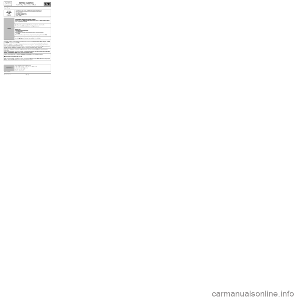
DF893
PRESENT
OR
STOREDCONTROLLED COOLANT THERMOSTAT CIRCUITCO: Open circuit
CC.0: Short circuit to earth
CC.1: Short circuit to + 12 V
1.DEF: EOBD
NOTESPriorities when dealing with a number of faults:
Deal first with fault DF084 Actuator relay control circuit or DF046 Battery voltage
if they are present or stored.
Conditions for applying the fault finding procedure to stored faults:
The fault is considered present when the engine is running.
Special note:
Controlled coolant thermostat:
–For CO and CC.1:
Thermostat not controlled; temperature regulation performed at 110˚C.
–For CC 0:
Thermostat continuously controlled; temperature regulation performed at 90˚C.
Use Wiring Diagram Technical Note for CLIO III or MODUS.
Check the condition of the controlled coolant thermostat connector (see Technical Note Wiring Diagram, CLIO III
or MODUS, component code 1458).
Check the condition of the engine management computer connector (see Technical Note Wiring Diagram,
CLIO III or MODUS, component code 120).
If the connectors are faulty and if there is a repair procedure (see Technical Note 6015A, Repairing electrical
wiring, Wiring: Precautions for repair), repair the connector, otherwise replace the wiring.
If the fault is still present, check (with the ignition on) for + 12 V on connection 3FB of the controlled coolant
thermostat.
If the connection is faulty and if there is a repair procedure (see Technical Note 6015A, Electrical wiring repair,
Wiring: Precautions for repair), repair the wiring, otherwise replace it.
Use the "universal bornier" to check the insulation and continuity of the following connection:
●3VL between components 1458 and 120.
If the connection is faulty and if there is a repair procedure (see Technical Note 6015A, Electrical wiring repair,
Wiring: Precautions for repair), repair the wiring, otherwise replace it.
SIM32_V4C_DF893
AFTER REPAIRFollow the instructions to confirm repair:
–If the fault is present, continue to deal with the fault.
–If the fault is stored, ignore it.
Deal with any other faults.
Clear the stored faults.