display RENAULT TWINGO RS 2009 2.G Electrical Equipment - Petrol Injection Workshop Manual
[x] Cancel search | Manufacturer: RENAULT, Model Year: 2009, Model line: TWINGO RS, Model: RENAULT TWINGO RS 2009 2.GPages: 348
Page 4 of 348
17B-4V7 MR-413-X44-17B000$010.mif
PETROL INJECTION
Fault finding – Introduction17B
SIM 32 Injection
Program no.: D3
Vdiag No.: 44, 4C, 50
and 54
Faults
Faults are declared present or stored (depending on whether they appeared in a certain context and have
disappeared since, or whether they remain present but are not diagnosed within the current context).
The present or stored status of faults should be considered when using the diagnostic tool after the + after ignition
feed is switched on (without any action on the system components).
For a present fault, apply the procedure described in the Interpretation of faults section.
For a stored fault, note the faults displayed and apply the Notes section.
If the fault is confirmed when the instructions are applied, the fault is present. Deal with the fault.
If the fault is not confirmed, check:
–the electrical lines which correspond to the fault,
–the connectors on these lines (corrosion, bent pins, etc.),
–the resistance of the faulty component,
–the condition of the wires (melted or split insulation, wear).
Conformity check
The aim of the conformity check is to check data that does not produce a fault on the diagnostic tool when the data
is inconsistent. Therefore, this stage is used to:
–carry out fault finding on faults that do not have a fault display, and which may correspond to a customer complaint,
–check that the system is operating correctly and that there is no risk of a fault recurring after repairs.
This section gives the fault finding procedures for statuses and parameters and the conditions for checking them
If a status does not function normally or a parameter is outside the permitted tolerance values, consult the
corresponding fault finding pages (see interpretation of statuses and parameters).
Customer complaints - Fault finding chart
If the test with the diagnostic tool is OK but the customer complaint is still present, the fault should be processed by
customer complaints.
A synopsis of the general procedure to follow is provided on the following page in the form of
a flow chart.
Page 16 of 348
17B-16V7 MR-413-X44-17B000$030.mif
PETROL INJECTION
Fault finding – System operation17B
SIM 32 Injection
Program no.: D3
Vdiag No.: 44, 4C, 50
and 54
–DF089 Inlet manifold pressure sensor fault 1.DEF: Signal inconsistency.
Or 2. DEF: Open circuit or short circuit.
Or 3. DEF: Non-compliance with emission control standards.
–DF091 Vehicle speed signal in 1.DEF: No multiplex signals or invalid values.
Or 2. DEF: Non-compliance with emission control standards.
–DF001 Coolant temperature sensor circuit in 1.DEF: Signal inconsistency.
Or 2. DEF: Open circuit or short circuit.
Or 3. DEF: Non-compliance with emission control standards.
–DF002 Air temperature circuit in 1. DEF: Open circuit or short circuit.
Or 2. DEF: Non-compliance with emission control standards.
–DF330 Pinking sensor circuit in 1.DEF: Open circuit or short circuit.
Or 2. DEF: Non-compliance with emission control standards.
–DF893 Controlled coolant thermostat circuit in CO: Open circuit.
Or CC.0: Short circuit to earth.
Or CC.1: Short circuit to + 12 volts.
Or 1. DEF: Non-compliance with emission control standards.
Engine torque limitation is activated.
If the fault is directly linked to the controlled thermostat (DF893 Controlled coolant thermostat circuit), the
thermostat is no longer controlled. It operates continuously, either in low temperature mode (instance of short circuit to
earth) or in high temperature mode (instance of open circuit or short circuit to the battery). The engine torque is limited
to limit heating and also to protect the engine by preventing overheating.
c. Functions affected by the presence of a controlled thermostat:
–Coolant temperature: 108˚C nominal, between 70˚C and 90˚C in defect mode or on loaded points.
–Coolant temperature fault finding: the fault finding setting for coolant temperature consistency has been adapted.
–Consumption: The function improves fuel consumption. Consequence: a fault with the function may lead to
inefficient consumption.
–Bleeding the circuit: A new procedure adapted to this innovation is described in MR 392 and 385, Mechanical
systems, CLIO III and MODUS, 19A Cooling, Cooling circuit: Bleeding.
–Coolant temperature display and illumination of the warning light on the instrument panel: During nominal
operation there is no impact as the temperature reference value is taken into account as well as the warning light
illumination thresholds. In the event of malfunction, see the summary table below.
–Fan unit and air conditioning: the fan unit activation threshold and the high temperature air conditioning
deactivation threshold are adapted in accordance with the temperature setpoint.
–Fault finding of controlled thermostat: Electrical fault finding is used. No operational fault finding:
A mechanical fault (such as jamming) will not be detected by the system.
–Performance: In the event of a fault, there is the option to switch the engine to reduced performance mode (see
Description of operation: Operation in defect mode). Note:
If a fault on the coolant temperature sensor is detected, fan assembly 1 is requested to operate permanently,
regardless of the management mode of the engine coolant temperature.
Page 17 of 348
17B-17V7 MR-413-X44-17B000$030.mif
PETROL INJECTION
Fault finding – System operation17B
SIM 32 Injection
Program no.: D3
Vdiag No.: 44, 4C, 50
and 54
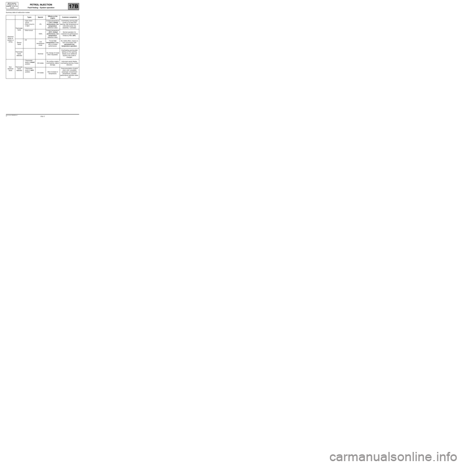
Summary table of malfunction modes:
Types SpecialEffects on the
engineCustomer complaints
Electrical
faults on
resistor or
wiringThermostat
faults–Open short
circuit
–Short circuit to
+ 12 V0%Coolant temperature
≈ 110˚C, limited
performance, low
temperature
reference value.Overheating warning light
comes on at each first
opening, high temperature on
instrument panel, fan
assembly 1 activated.
–Short circuit
100%Coolant temperature
≈ 90˚C, limited
performance, low
temperature
reference value.Normal operation for
customer but performance
limited by 10 to 20%.
Sensor
faults–All
Low
temperature
modeForced low
temperature mode,
with no limited
performance.No visible effect, impact on
fuel consumption with
permanent low
temperature operation.
Thermostat
faults
detectedNominalNo change of mode
when requested.Overheating warning light
lighting on first opening,
display of an additional
square if the mode is
changed.
Non-
electrical
faultsThermostat
faults
detected–Thermostat
stuck in closed
positionAll modesNo cooling, engine
overheating, engine
damage.Instrument panel display,
overheating warning, torque
reduction.
–Thermostat
stuck in open
position
All modesSlow increase in
temperature.Overconsumption of petrol
when cold, unsuitable
passenger compartment
temperature, possible
performance reduction when
cold.
Page 28 of 348
17B-28V7 MR-413-X44-17B000$070.mif
17B
SIM 32 Injection
Program no.: D3
Vdiag No.: 44, 4C, 50
and 54
1. OPERATING SAFETY
Activation of the warning lights
The SIM32 injection system manages the illumination of three warning lights according to the severity of the faults
detected, to inform the customer and to assist with fault finding.
The injection computer manages the activation of the warning lights on the instrument panel. These warning lights
illuminate during the starting phase and in the event of an injection fault or engine overheating.
The warning light activation commands are sent to the instrument panel.
Warning light illumination principle
When the ignition is switched on, the OBD (On Board Diagnostic) warning light is illuminated for approximately
3 seconds and is then extinguished.
If there is an injection fault (severity level 1), the SERVICE warning light is illuminated.
It indicates a reduced level of operation and a limited safety level.
The user must carry out repairs as soon as possible:
–motorised throttle valve,
–accelerator pedal potentiometer,
–inlet manifold pressure sensor,
–computer,
–actuator feed,
–the computer power supply,
–turbocharger pressure sensor (for D4FT 780).
For faults requiring the driver to stop the engine quickly, the severity level 2 warning light is illuminated.
If a fault causing excessive exhaust gas pollution is detected, the orange OBD warning light engine symbol is
illuminated:
–the light flashes if the fault could lead to a risk of destroying catalytic converter (destructive engine misfire). If this
happens, the vehicle must be stopped immediately.
–the light is permanently illuminated if the emission control standards are not met (pollutant engine misfire,
catalytic converter fault, oxygen sensor fault, inconsistency between the oxygen sensors and a fuel vapour
absorber fault).
Mileage travelled with fault
The parameter PR106 Mileage counter fault warning light illuminated displays the mileage covered and
illuminates one of the injection fault warning lights: fault severity level 1 (amber) and 2 (red). The parameter
PR105 Mileage counter OBD fault warning light illuminated displays the mileage covered and illuminates the
OBD warning light.
This counter is reset to 0 using the diagnostic tool via the command RZ001 Fault memory.
PETROL INJECTION
Fault finding – Role of components
Page 30 of 348
17B-30V7 MR-413-X44-17B000$070.mif
PETROL INJECTION
Fault finding – Role of components17B
SIM 32 Injection
Program no.: D3
Vdiag No.: 44, 4C, 50
and 54
Injection computer:
The injection computer manages the entire system.
Its role is to define the engine optimum operating mode and to inform the driver (via the instrument panel, information
display, and buzzer) and to communicate with the other computers.
Fuel vapour recirculation solenoid valve:
The fuel vapour absorber works like a ''sponge'' for petrol vapours and enables gases coming from the tank to be
collected.
Upstream oxygen sensor:
This sensor measures the amount of oxygen in the exhaust gas.
The voltage supplied to the computer by the sensor indicates the amount of oxygen in the exhaust gas - a rich
mixture or a lean mixture - and a program is adopted accordingly.
Downstream oxygen sensor:
This sensor measures the amount of oxygen in the exhaust gas.
The voltage supplied to the computer by the sensor indicates the amount of oxygen in the exhaust gas - a rich
mixture or a lean mixture - and a program is adopted accordingly.
Pinking sensor:
The sensor detects engine knocking and sends its electrical signal to the injection computer.
Oil pressure sensor:
This sensor measures the engine oil pressure.
Turbocharger:
The turbocharger is used to supply the engine with more air.
Turbocharger pressure sensor:
This sensor indicates the pressure at the turbocharger air cooler outlet before the damper valve.
Ignition coil:
This acts both as an energy storage battery and a transformer. It generates high voltage ignition pulses and the
energy required to ignite the mixture.
Motorised throttle valve:
The motorised throttle valve supplies the engine with varying mixtures of fuel and air according to the load required.
This electronic control detects the position of the accelerator using a sensor (potentiometer) to inject the mixture.
Page 35 of 348
17B-35V7 MR-413-X44-17B000$090.mif
17B
SIM 32 Injection
Program no.: D3
Vdiag No.: 44, 4C, 50
and 54
1. COMPUTER REPLACEMENT OR REPROGRAMMING OPERATIONS
Computer replacement or reprogramming for engines with the OCS (customised oil change interval)
function.
For Vdiag 44 and 4C, commands SC001 and SC003 are not accessible.
The system can be programmed via the diagnostic socket using the RENAULT CLIP diagnostic tool (refer to
Technical Note 3585A, COMPUTER PROGRAMMING AND REPROGRAMMING PROCEDURE or follow the
instructions given by the diagnostic tool). Only in Vdiag 54 and certain engines in Vdiag 50:
For Vdiag 50, the procedure below should be followed only if ET840 Customised Oil Change Interval is ACTIVE.
Certain variables linked to the O.C.S and the details of the last four oil services are saved by the computer.
However, all data saved is cleared during a reprogramming operation. When replacing or reprogramming the
computer, it is necessary to save the data from the old computer so it can be written to the new computer
(or reprogrammed). To do this before changing (or reprogramming) the computer, it is necessary to run the request
SC003 Save computer data, and after it has been changed (or reprogrammed), it is necessary to run the request
SC001 Write saved data.
For Vdiag 50, if ET840 Customised Oil Change Interval is INACTIVE, commands SC001 and SC003 should
not be used.
Operations to check before reprogramming the injection computer:
Before reprogramming the injection computer, move the main Cruise control/Speed limiter switch to the rest
position. The information about the cruise control or the speed limiter displayed on the instrument panel
disappears.
Otherwise, if the main switch remains in the cruise control or speed limiter position during and after reprogramming,
the Cruise control/Speed limiter function will not be operational.
The procedure for resetting the function is as follows:
Ignition switched on and main switch in rest position (the computer detects rest position at that moment).
Switch in Cruise control position to activate the Cruise control function.
Switch in Speed limiter position to activate the Speed limiter function.
IMPORTANT:
–Switch on the diagnostic tool (mains or cigarette lighter supply).
–Connect a battery charger.
–Switch off all electrical consumers (lights, interior lighting, air conditioning, radio, etc.).
–Wait for the engine to cool (engine coolant temperature below 60˚C and air temperature below 50˚C).
PETROL INJECTION
Fault finding – Replacement of components
Page 43 of 348
17B-43V7 MR-413-X44-17B000$131.mif
17B
SIM 32 Injection
Program no.: D3
Vdiag No.: 44, 4C, 50
and 54
* EOBD: European On Board Diagnostics
DF001
PRESENT
OR
STOREDCOOLANT TEMPERATURE SENSOR CIRCUIT
1.DEF: signal incoherence
2.DEF: abnormal voltage
3.DEF: EOBD*
NOTESConditions for applying the fault finding procedure to stored faults:
The fault is declared present when the ignition is switched on.
Special notes:
If the fault is present, the EOBD* warning light is illuminated and the low speed engine
cooling fan is permanently activated.
1.DEF: Consult the parameter PR064 Coolant temperature:
If the tool displays 120˚C, this indicates a short circuit to 12V or an open circuit.
If the tool displays - 40˚C, this indicates a short circuit to earth.
Use the Wiring Diagrams Technical Note for NEW TWINGO, E33, CLIO III,
or MODUS.
Check the condition of the connector of the coolant temperature sensor (component code 244) and of the engine
management computer (component code 120).
If the connector or connectors are faulty and if there is a repair procedure (see Technical Note 6015A, Repairing
electrical wiring, Wiring: Precautions for repair), repair the connector, otherwise replace the wiring.
Measure the resistance of the coolant temperature sensor, component code 244 between the connections 3C and
3JK:
●at 10˚C: 12030 Ω < X < 12890 Ω,
●at 25˚C: 2195 Ω < X < 2309 Ω,
●at 50˚C: 795.5 Ω < X < 826.5 Ω,
●at 80˚C: 279.3 Ω < X < 286.7 Ω.
If the coolant temperature sensor resistances are not correct, replace the coolant temperature sensor.
Check the insulation and continuity of the following connections:
●3C between components 120 and 244,
●3JK between the components 120 and 244.
If the connection or connections are faulty and there is a repair procedure (see Technical Note 6015A, Electrical
wiring repair, Wiring: Precautions for repair), repair the wiring, otherwise replace it.
If the fault is still present, contact Techline.
SIM32_V44_DF001/SIM32_V4C_DF001/SIM32_V50_DF001/SIM32_V54_DF001
PETROL INJECTION
Fault finding – Interpretation of faults
AFTER REPAIRDeal with any other faults. Clear the fault memory.
Switch off the ignition, wait 1 minute and carry out a road test followed by a check with
the diagnostic tool.
Page 44 of 348
17B-44V7 MR-413-X44-17B000$131.mif
PETROL INJECTION
Fault finding – Interpretation of faults17B
SIM 32 Injection
Program no.: D3
Vdiag No.: 44, 4C, 50
and 54
DF002
PRESENT
OR
STOREDAIR TEMPERATURE SENSOR CIRCUIT
1.DEF: Abnormal voltage
2.DEF: EOBD
NOTESConditions for applying the fault finding procedure to stored faults:
The fault is declared present, with the ignition on.
Special notes:
The OBD warning light is lit.
Consult the parameters PR059 Air inlet temperature:
If the tool displays 120˚C, this indicates a short circuit to 12V or an open circuit.
If the tool displays - 40˚C, this indicates a short circuit to earth.
Use the Wiring Diagrams Technical Note for NEW TWINGO, E33, CLIO III,
or MODUS.
Check the condition of the connector of the air temperature sensor (component code 272) and of the engine
management computer (component code 120).
If the connector or connectors are faulty and if there is a repair procedure (see Technical Note 6015A, Electrical
wiring repair, Wiring: Precautions for repair), repair the connector, otherwise change the wiring.
Measure the resistance of the air temperature sensor, component code 272 between connections 3B and 3JQ:
●at 25˚C: 1928 Ω < X < 2174 Ω,
●at 50˚C: 763 Ω < X < 857 Ω.
If the air temperature sensor resistances are not correct, replace the air temperature sensor.
Check the insulation and continuity of the following connections:
●3B between components 120 and 272,
●3JQ between the components 120 and 272.
If the connection or connections are faulty and there is a repair procedure (see Technical Note 6015A, Electrical
wiring repair, Wiring: Precautions for repair), repair the wiring, otherwise replace it.
If the fault is still present, contact Techline.
SIM32_V44_DF002/SIM32_V4C_DF002/SIM32_V50_DF002/SIM32_V54_DF002
AFTER REPAIRDeal with any other faults. Clear the fault memory.
Switch off the ignition, wait 1 minute and carry out a road test followed by a check with
the diagnostic tool.
Page 131 of 348
17B-131V7 MR-413-X44-17B000$133.mif
PETROL INJECTION
Fault finding – Interpretation of faults17B
SIM 32 Injection
Program no.: D3
Vdiag No.: 44, 4C, 50
and 54
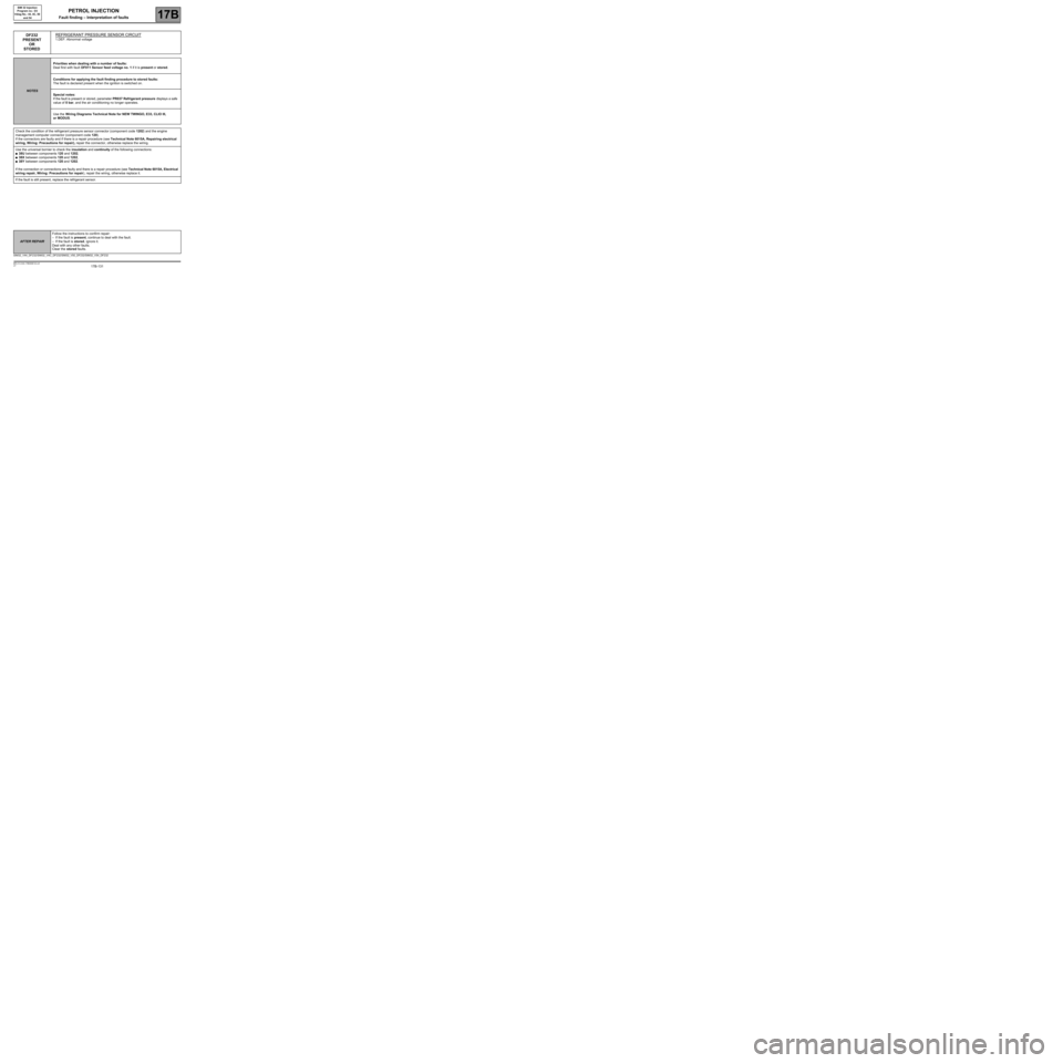
DF232
PRESENT
OR
STOREDREFRIGERANT PRESSURE SENSOR CIRCUIT
1.DEF: Abnormal voltage
NOTESPriorities when dealing with a number of faults:
Deal first with fault DF011 Sensor feed voltage no. 1 if it is present or stored.
Conditions for applying the fault finding procedure to stored faults:
The fault is declared present when the ignition is switched on.
Special notes:
If the fault is present or stored, parameter PR037 Refrigerant pressure displays a safe
value of 0 bar, and the air conditioning no longer operates.
Use the Wiring Diagrams Technical Note for NEW TWINGO, E33, CLIO III,
or MODUS.
Check the condition of the refrigerant pressure sensor connector (component code 1202) and the engine
management computer connector (component code 120).
If the connectors are faulty and if there is a repair procedure (see Technical Note 6015A, Repairing electrical
wiring, Wiring: Precautions for repair), repair the connector, otherwise replace the wiring.
Use the universal bornier to check the insulation and continuity of the following connections:
●38U between components 120 and 1202,
●38X between components 120 and 1202,
●38Y between components 120 and 1202.
If the connection or connections are faulty and there is a repair procedure (see Technical Note 6015A, Electrical
wiring repair, Wiring: Precautions for repair), repair the wiring, otherwise replace it.
If the fault is still present, replace the refrigerant sensor.
SIM32_V44_DF232/SIM32_V4C_DF232/SIM32_V50_DF232/SIM32_V54_DF232
AFTER REPAIRFollow the instructions to confirm repair:
–If the fault is present, continue to deal with the fault.
–If the fault is stored, ignore it.
Deal with any other faults.
Clear the stored faults.
Page 160 of 348
17B-160V7 MR-413-X44-17B000$133.mif
PETROL INJECTION
Fault finding – Interpretation of faults17B
SIM 32 Injection
Program no.: D3
Vdiag No.: 44, 4C, 50
and 54
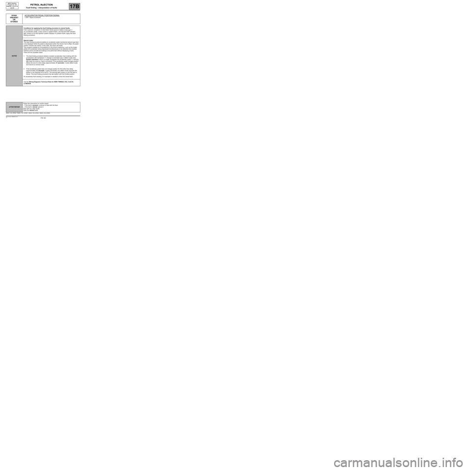
DF650
PRESENT
OR
STOREDACCELERATOR PEDAL POSITION SIGNAL
1.DEF: Signal incoherent
NOTESConditions for applying the fault finding procedure to stored faults:
If the customer complains of intermittent faults typical of defect mode type 3
(no accelerator pedal, cruise control or speed limiter), and that the ESP indicator
light comes on but the injection system displays no present faults, apply this fault
finding procedure.
Special notes:
This fault finding procedure enables an accelerator pedal mechanical seizure type fault
to be displayed whilst the pedal is depressed (when the driver's foot is lifted, the pedal
position remains the same). In this case, the driver will brake.
This program enables an inconsistency in the driver's behaviour, such as the brake
pedal and accelerator being depressed simultaneously to be detected (but enables
heel/toe points and left foot braking to be performed without displaying a fault).
There are two possible cases:
1. The fault finding procedure detects constant acceleration then braking with the
acceleration still maintained => change to reversible type 3 defect mode (see
System operation) which no longer recognises the accelerator pedal => warning
light does not come on, fault is not stored. If the accelerator pedal changes position
before the end of a time delay (approximately 31 seconds), it exits defect mode
and returns to normal mode.
2. If the accelerator pedal does not change position for the entire time delay
(approximately 31 seconds), it goes irreversibly into defect mode (requires the
ignition to be switched off to exit it). The warning light comes on and the fault is
stored. This fault finding procedure has no relation with the throttle position.
An accelerator fault (locking, for example) is needed to show the stored fault.
Use the Wiring Diagrams Technical Note for NEW TWINGO, E33, CLIO III,
or MODUS.
SIM32_V44_DF650 / SIM32_V4C_DF650 / SIM32_V50_DF650 / SIM32_V54_DF650
AFTER REPAIRFollow the instructions to confirm repair:
–If the fault is present, continue to deal with the fault.
–If the fault is stored, ignore it.
Deal with any other faults.
Clear the stored faults.