headlight RENAULT TWINGO RS 2009 2.G Electrical Equipment User Guide
[x] Cancel search | Manufacturer: RENAULT, Model Year: 2009, Model line: TWINGO RS, Model: RENAULT TWINGO RS 2009 2.GPages: 241
Page 21 of 241
80B-9
HEADLIGHTS
Halogen headlight: Adjustment
80B
ADJUSTMENT
I - PREPARATION OPERATION
aPlace the vehicle on a level horizontal working area.
aDo not apply the parking brake.
aCheck and inflate the tyres (see Tyre pressure)
(MR 411, 35A, Wheels and tyres).
aOpen the cover.
aCheck:
-that the luggage compartment is empty,
-that the headlights are clean.
aPosition the headlight beam remote adjustment con-
trol on 0.
aSwitch on the dipped headlights.
II - TEST OPERATION
aPlace a headlight adjustment and checking tool
set to -1% in front of the vehicle (see equipment ins-
tructions).
aCheck the headlight beam adjustment using the
headlight adjustment and checking tool (see the
instructions for the equipment).III - ADJUSTMENT OPERATION
aUsing the headlight adjustment and checking
tool :
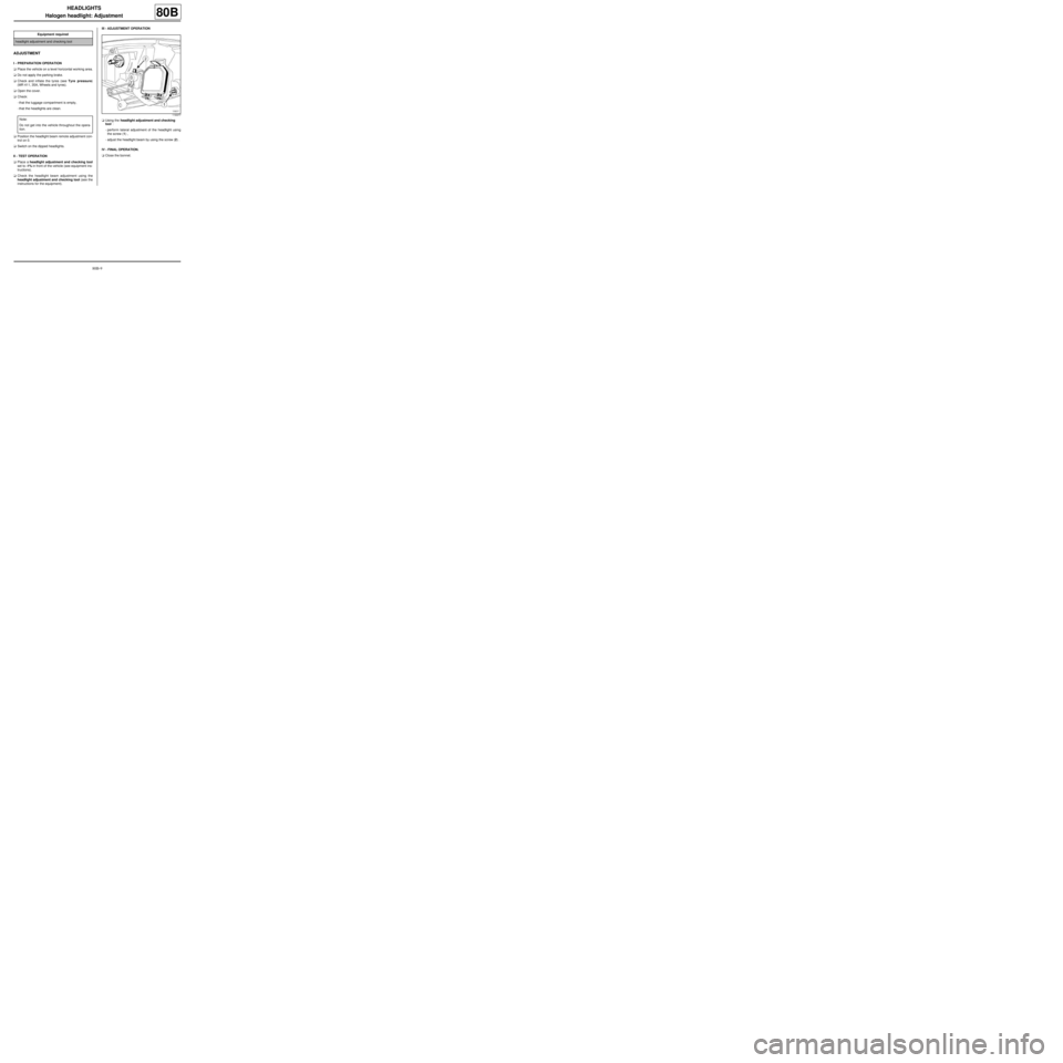
-perform lateral adjustment of the headlight using
the screw (1) ,
-adjust the headlight beam by using the screw (2) .
IV - FINAL OPERATION.
aClose the bonnet. Equipment required
headlight adjustment and checking tool
Note:
Do not get into the vehicle throughout the opera-
tion.
119377
Page 22 of 241
80B-10
HEADLIGHTS
Front fog light: Removal - Refitting
80B
REMOVAL
I - REMOVAL PREPARATION OPERATION
Removing the left-hand fog light bulb
a
aPosition the vehicle on a two-post lift (see Vehicle:
Towing and lifting) (02A, Lifting equipment).
aRemove:
-the front wheels (see Wheel: Removal - Refitting)
(35A, Wheels and tyres),
-the front wheel arch liners (see Front wheel arch
liner: Removal - Refitting) (55A, Exterior protec-
tion),
-the front bumper (see Front bumper: Removal -
Refitting) (55A, Exterior protection).Removing the fog light bulb
aRemove:
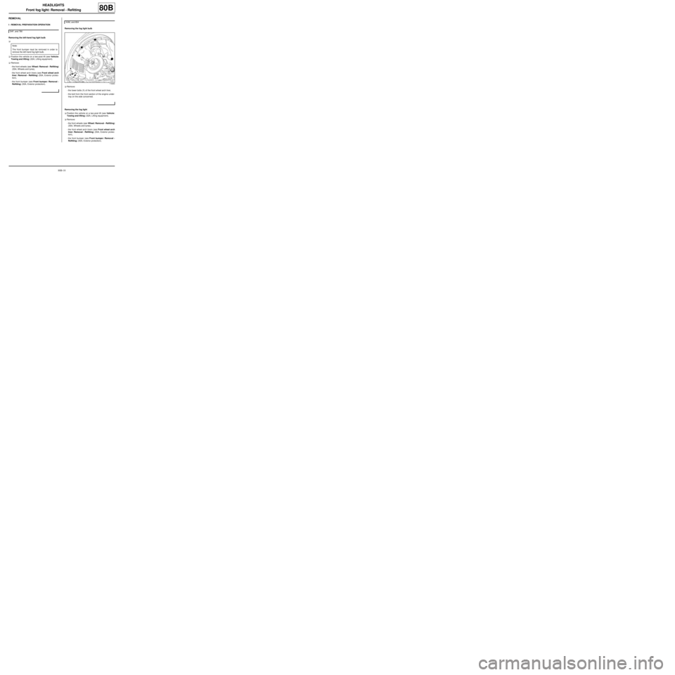
-the lower bolts (1) of the front wheel arch liner,
-the bolt from the front section of the engine under-
tray on the side concerned.
Removing the fog light
aPosition the vehicle on a two-post lift (see Vehicle:
Towing and lifting) (02A, Lifting equipment).
aRemove:
-the front wheels (see Wheel: Removal - Refitting)
(35A, Wheels and tyres),
-the front wheel arch liners (see Front wheel arch
liner: Removal - Refitting) (55A, Exterior protec-
tion),
-the front bumper (see Front bumper: Removal -
Refitting) (55A, Exterior protection). D4F, and 780
Note:
The front bumper must be removed in order to
remove the left-hand fog light bulb.
K4M, and 854
119264
Page 23 of 241
80B-11
HEADLIGHTS
Front fog light: Removal - Refitting
80B
II - OPERATION FOR REMOVAL OF PART
CONCERNED
1 - Removing the fog light bulb
a
aDisconnect the fog light connector.
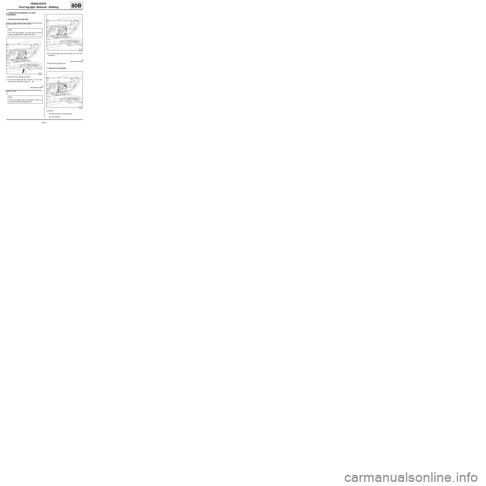
aTurn the fog light bulb (3) a quarter of a turn anti-
clockwise by reaching through
b (2) .
aaTurn the fog light bulb (4) a quarter of a turn anti-
clockwise.
aRemove the fog light bulb.
2 - Removal of the fog light
aRemove:
-the bolts (5) from the front fog light,
-the front fog light. K4M, and 854 – D4F or D7F or K9K
Note:
For D4F/780 engines, the right-hand fog light
bulb is accessed from under the vehicle.
121079
D4F, and 780
Note:
The front bumper must be removed in order to
remove the left-hand fog light bulb.
121079
121079
Page 24 of 241
80B-12
HEADLIGHTS
Front fog light: Removal - Refitting
80B
REFITTING
I - REFITTING OPERATION FOR PART
CONCERNED
1 - Refitting the fog light bulb
aReplace the fog light bulb with an approved bulb.
aRefit the fog light bulb.
aTurn the fog light bulb a quarter of a turn clockwise.
aConnect the fog light connector.
2 - Refitting the fog light
aRefit the front fog light.
II - FINAL OPERATION.
Refitting the left-hand fog light bulb
aRefit:
-the front bumper (see Front bumper: Removal -
Refitting) (55A, Exterior protection),
-the front wheel arch liners (see Front wheel arch
liner: Removal - Refitting) (55A, Exterior protec-
tion),
-the front wheels (see Wheel: Removal - Refitting)
(35A, Wheels and tyres).
Refitting the fog light bulb
aRefit:
-the lower bolts of the front wheel arch liner,
-the bolt for the front section of the engine undertray
on the side concerned.
Refitting the fog light
aRefit:
-the front bumper (see Front bumper: Removal -
Refitting) (55A, Exterior protection),-the front wheel arch liners (see Front wheel arch
liner: Removal - Refitting) (55A, Exterior protec-
tion),
-the front wheels (see Wheel: Removal - Refitting)
(35A, Wheels and tyres).
D4F, and 780
K4M, and 854
Page 25 of 241
80B-13
HEADLIGHTS
Side indicator: Removal - Refitting
80B
REMOVAL
OPERATION FOR REMOVAL OF PART
CONCERNED
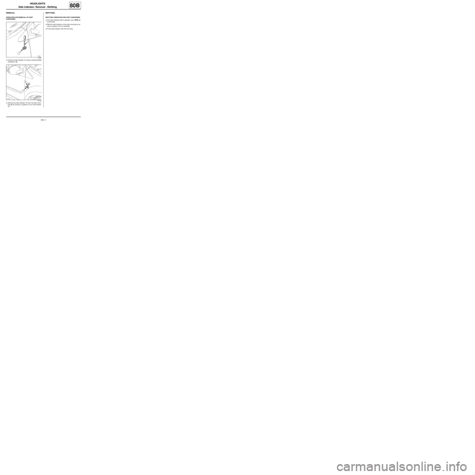
aUnclip the side indicator (1) using a small flat-blade
screwdriver (2) .
aRemove the side indicator (1) from the bulb moun-
ting (3) by turning it a quarter of a turn anti-clockwi-
se.
REFITTING
REFITTING OPERATION FOR PART CONCERNED
aIf the side indicator bulb is replaced, use a W5W ap-
proved bulb.
aRefit the side indicator on the bulb mounting by tur-
ning it a quarter of a turn clockwise.
aFit the side indicator onto the front wing.
119384
121206
Page 96 of 241
85A-26
WIPING - WASHING
Windscreen washer reservoir: Removal - Refitting
85A
REMOVAL
I - REMOVAL PREPARATION OPERATION
aPosition the vehicle on a two-post lift (see Vehicle:
Towing and lifting) (MR 411, 02A, Lifting equip-
ment).
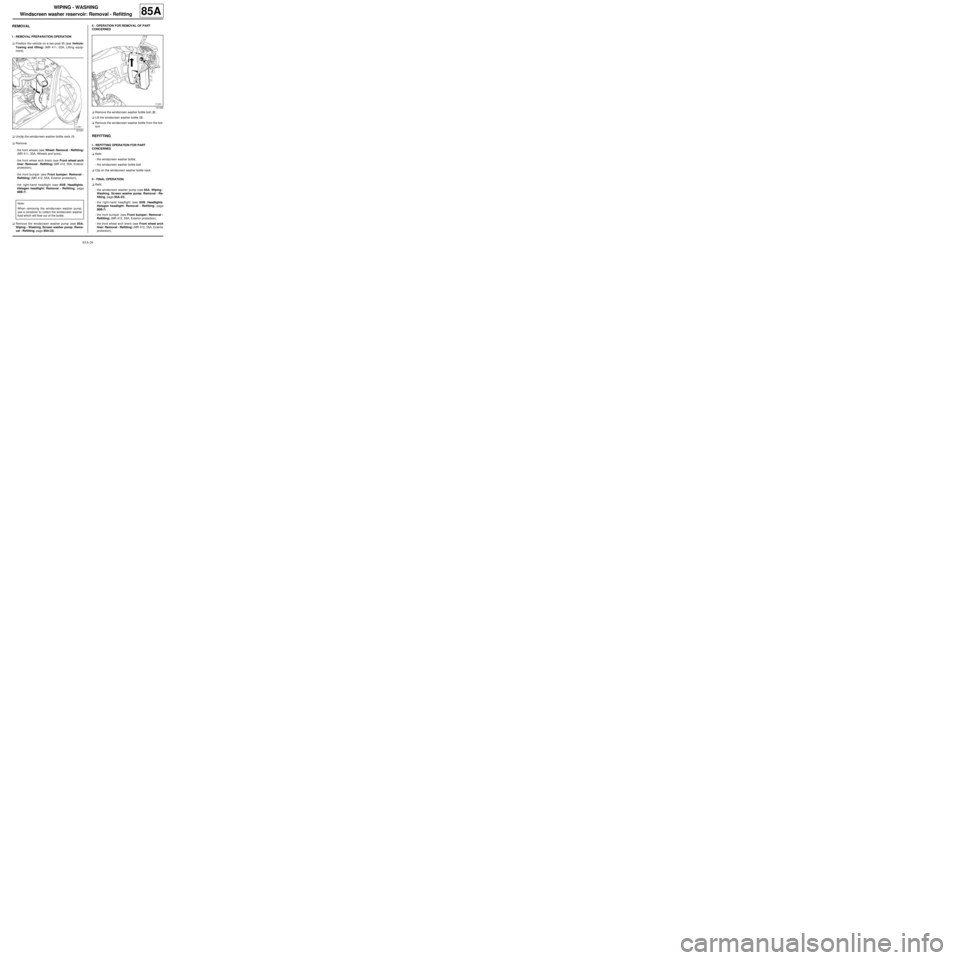
aUnclip the windscreen washer bottle neck (1) .
aRemove:
-the front wheels (see Wheel: Removal - Refitting)
(MR 411, 35A, Wheels and tyres),
-the front wheel arch liners (see Front wheel arch
liner: Removal - Refitting) (MR 412, 55A, Exterior
protection),
-the front bumper (see Front bumper: Removal -
Refitting) (MR 412, 55A, Exterior protection),
-the right-hand headlight (see 80B, Headlights,
Halogen headlight: Removal - Refitting, page
80B-7) .
aRemove the windscreen washer pump (see 85A,
Wiping - Washing, Screen washer pump: Remo-
val - Refitting, page 85A-23) .II - OPERATION FOR REMOVAL OF PART
CONCERNED
aRemove the windscreen washer bottle bolt (2) .
aLift the windscreen washer bottle (3) .
aRemove the windscreen washer bottle from the bot-
tom.
REFITTING
I - REFITTING OPERATION FOR PART
CONCERNED
aRefit:
-the windscreen washer bottle,
-the windscreen washer bottle bolt.
aClip on the windscreen washer bottle neck.
II - FINAL OPERATION.
aRefit:
-the windscreen washer pump (see 85A, Wiping -
Washing, Screen washer pump: Removal - Re-
fitting, page 85A-23) ,
-the right-hand headlight (see 80B, Headlights,
Halogen headlight: Removal - Refitting, page
80B-7) ,
-the front bumper (see Front bumper: Removal -
Refitting) (MR 412, 55A, Exterior protection),
-the front wheel arch liners (see Front wheel arch
liner: Removal - Refitting) (MR 412, 55A, Exterior
protection),
121091
Note:
When removing the windscreen washer pump,
use a container to collect the windscreen washer
fluid which will flow out of the bottle.
121090
Page 97 of 241
85A-27
WIPING - WASHING
Windscreen washer reservoir: Removal - Refitting
85A
-the front wheels (see Wheel: Removal - Refitting)
(MR 411, 35A, Wheels and tyres).
aFill the windscreen washer bottle.
aAdjust the headlight beam (see 80B, Headlights,
Halogen headlight: Adjustment, page 80B-9) .
Page 139 of 241
88A-3
WIRING HARNESS
Front left-hand wiring: Removal - Refitting
LEFT-HAND DRIVE
88A
REMOVAL
I - REMOVAL PREPARATION OPERATION
a
aPosition the vehicle on a two-post lift (see Vehicle:
Towing and lifting) (MR 411, 02A, Lifting equip-
ment).
aSwitch off the ignition.
aRemove:
-the battery (see 80A, Battery, Battery: Removal -
Refitting, page 80A-2) ,
-the battery tray (see 80A, Battery, Battery tray:
Removal - Refitting, page 80A-6) ,
-the front wheel arch liners (see Front wheel arch
liner: Removal - Refitting) (MR 412, 55A, Exterior
protection),
-the front bumper (see Front bumper: Removal -
Refitting) (MR 412, 55A, Exterior protection),
-the side indicators (see 80B, Headlights, Side in-
dicator: Removal - Refitting, page 80B-13) ,
-the master cylinder (see Master cylinder: Remo-
val - Refitting) (MR 411, 37A, Mechanical compo-
nent controls),
-the brake servo (see Brake servo: Removal - Re-
fitting) (MR 411, 37A, Mechanical component con-
trols),
-the left-hand suspended engine mounting (see
Left-hand suspended engine mounting: Remo-
val - Refitting) (MR 411, 19D, Engine mounting).aUnclip the glovebox.
aRemove the dashboard lower trim.
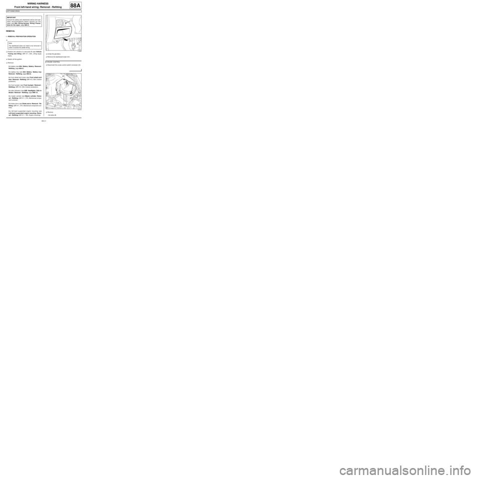
aDisconnect the cruise control switch connector (1) .
aRemove:
-the bolts (2) IMPORTANT
Consult the safety and cleanliness advice and ope-
ration recommendations before carrying out any
repair (see 88A, Wiring harness, Wiring: Precau-
tions for the repair, page 88A-2) .
Note:
The dashboard does not need to be removed in
order to access the pedal wiring.
119506
CRUISE CONTROL
121212
Page 142 of 241
88A-6
WIRING HARNESS
Front left-hand wiring: Removal - Refitting
LEFT-HAND DRIVE
88A
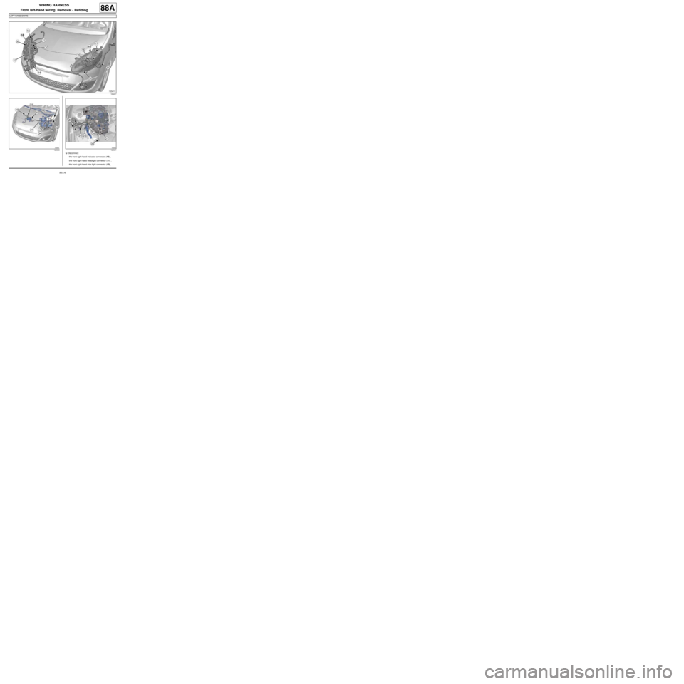
aDisconnect:
-the front right-hand indicator connector (10) ,
-the front right-hand headlight connector (11) ,
-the front right-hand side light connector (12) ,
125417
122340122341
Page 143 of 241
88A-7
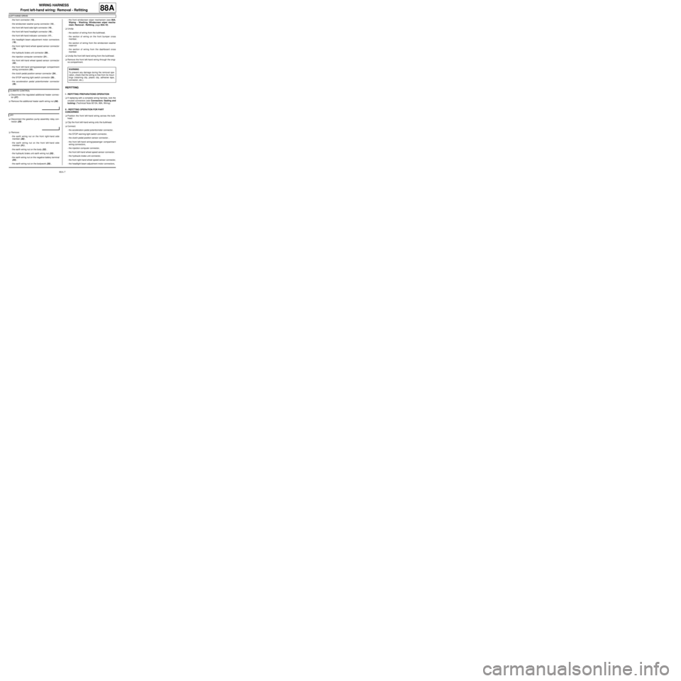
WIRING HARNESS
Front left-hand wiring: Removal - Refitting
LEFT-HAND DRIVE
88A
-the horn connector (13) ,
-the windscreen washer pump connector (14) ,
-the front left-hand side light connector (15) ,
-the front left-hand headlight connector (16) ,
-the front left-hand indicator connector (17) ,
-the headlight beam adjustment motor connectors
(18) ,
-the front right-hand wheel speed sensor connector
(19) ,
-the hydraulic brake unit connector (20) ,
-the injection computer connector (21) ,
-the front left-hand wheel speed sensor connector
(22) ,
-the front left-hand wiring/passenger compartment
wiring connectors (23) ,
-the clutch pedal position sensor connector (24) ,
-the STOP warning light switch connector (25) ,
-the acceleration pedal potentiometer connector
(26) .
aDisconnect the regulated additional heater connec-
tor (27) .
aRemove the additional heater earth wiring nut (28) .
aDisconnect the gearbox pump assembly relay con-
nector (29) .
aRemove:
-the earth wiring nut on the front right-hand side
member (30) ,
-the earth wiring nut on the front left-hand side
member (31) ,
-the earth wiring nut on the body (32) ,
-the hydraulic brake unit earth wiring nut (33) ,
-the earth wiring nut on the negative battery terminal
(34) ,
-the earth wiring nut on the bodywork (35) ,-the front windscreen wiper mechanism (see 85A,
Wiping - Washing, Windscreen wiper mecha-
nism: Removal - Refitting, page 85A-10) .
aUnclip:
-the section of wiring from the bulkhead,
-the section of wiring on the front bumper cross
member,
-the section of wiring from the windscreen washer
reservoir
-the section of wiring from the dashboard cross
member.
aUnclip the front left-hand wiring from the bulkhead.
aRemove the front left-hand wiring through the engi-
ne compartment.
REFITTING
I - REFITTING PREPARATIONS OPERATION
aIf replacing with a complete wiring harness, lock the
unused connectors (see Connectors: Sealing and
locking) (Technical Note 6015A, 88A, Wiring).
II - REFITTING OPERATION FOR PART
CONCERNED
aPosition the front left-hand wiring across the bulk-
head.
aClip the front left-hand wiring onto the bulkhead.
aConnect:
-the acceleration pedal potentiometer connector,
-the STOP warning light switch connector,
-the clutch pedal position sensor connector ,
-the front left-hand wiring/passenger compartment
wiring connectors,
-the injection computer connector,
-the front left-hand wheel speed sensor connector,
-the hydraulic brake unit connector,
-the front right-hand wheel speed sensor connector,
-the headlight beam adjustment motor connectors, CLIMATE CONTROL
JH1
WARNING
To prevent any damage during the removal ope-
ration, check that the wiring is free from its moun-
tings (retaining clip, plastic clip, adhesive tape,
connector, etc.).