87B-84
MR-413-X44-87B000$528.mif
V5
87B
PASSENGER COMPARTMENT CONNECTION UNIT
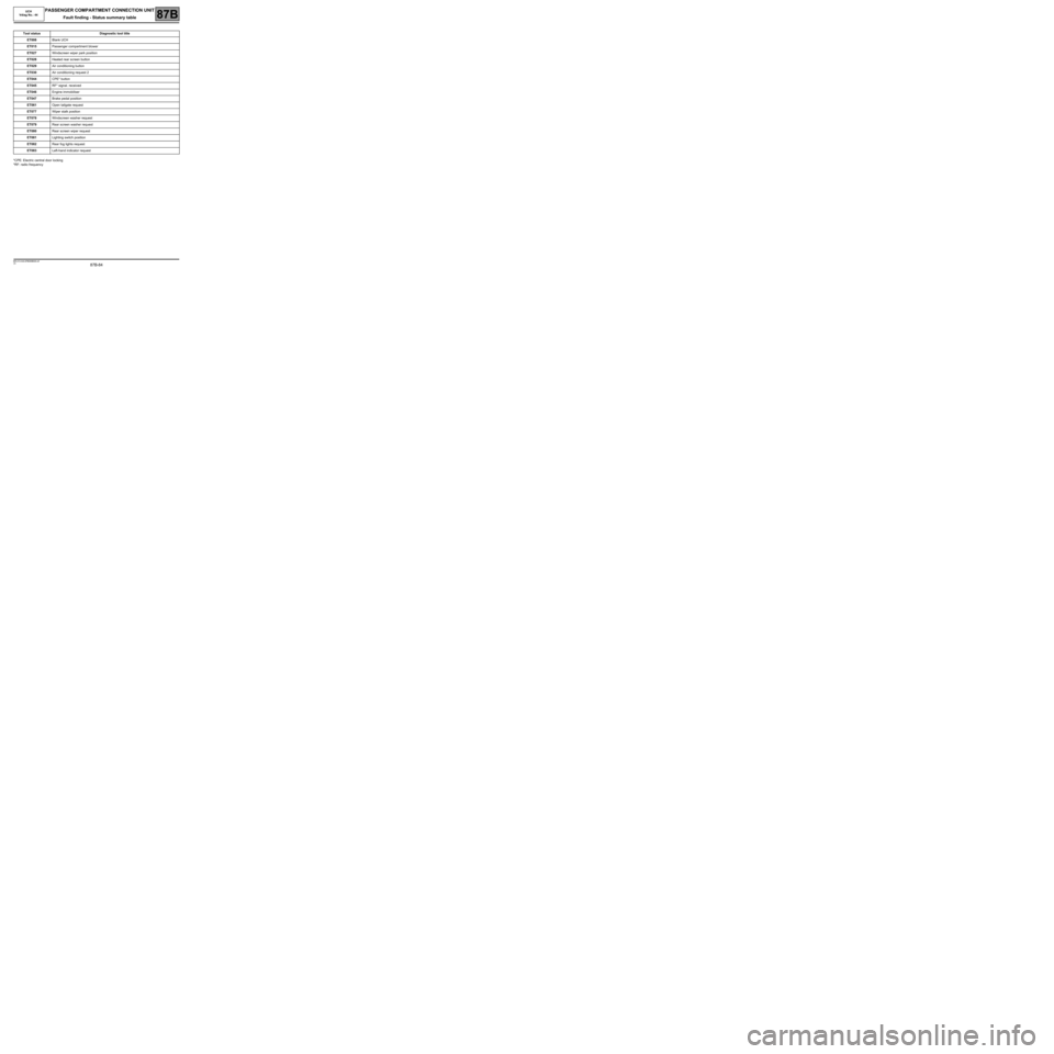
Fault finding - Status summary table
*CPE: Electric central door locking
*RF: radio frequencyTool status Diagnostic tool title
ET008Blank UCH
ET015Passenger compartment blower
ET027Windscreen wiper park position
ET028Heated rear screen button
ET029Air conditioning button
ET030Air conditioning request 2
ET044CPE* button
ET045RF* signal. received
ET046Engine immobiliser
ET047Brake pedal position
ET061Open tailgate request
ET077Wiper stalk position
ET078Windscreen washer request
ET079Rear screen washer request
ET080Rear screen wiper request
ET081Lighting switch position
ET082Rear fog lights request
ET083Left-hand indicator request
MR-413-X44-87B000$528.mif
UCH
Vdiag No.: 44
87B -100
MR-413-X44-87B000$576.mif
V5
PASSENGER COMPARTMENT CONNECTION UNIT
Fault finding - Interpretation of statuses
UCH
Vdiag No.: 44
87B
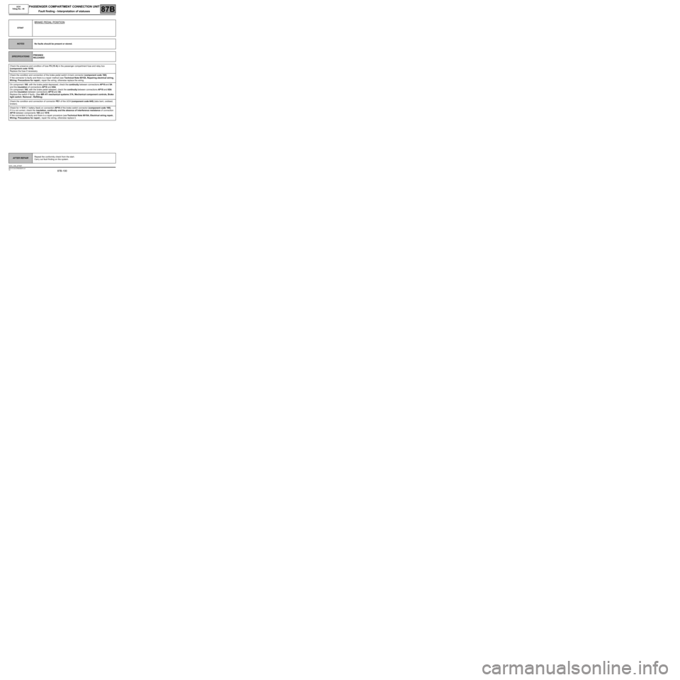
ET047
BRAKE PEDAL POSITION
NOTESNo faults should be present or stored.
SPECIFICATIONSPRESSED
RELEASED
Check the presence and condition of fuse F5 (15 A) in the passenger compartment fuse and relay box
(component code 1016).
Replace the fuse if necessary.
Check the condition and connection of the brake pedal switch 4-track connector (component code 160).
If the connector is faulty and there is a repair method (see Technical Note 6015A, Repairing electrical wiring,
Wiring: Precautions for repair), repair the wiring, otherwise replace the wiring.
On component 160, with the brake pedal depressed, check the continuity between connections AP10 and 5A
and the insulation of connections AP10 and 65A.
On component 160, with the brake pedal released, check the continuity between connections AP10 and 65A
and the insulation between connections AP10 and 5A.
Replace the switch if faulty. (See MR 411 mechanical systems 37A, Mechanical component controls, Brake
light switch: Removal - Refitting).
Check the condition and connection of connector PE1 of the UCH (component code 645) (tabs bent, oxidised,
broken).
Check for + 12 V (+ battery feed) on connection AP10 of the brake switch connector (component code 160).
If it is not correct, check the insulation, continuity and the absence of interference resistance of connection
AP10 between components 160 and 1016.
If the connection is faulty and there is a repair procedure (see Technical Note 6015A, Electrical wiring repair,
Wiring: Precautions for repair), repair the wiring, otherwise replace it.
AFTER REPAIRRepeat the conformity check from the start.
Carry out fault finding on the system.
UCH_V44_ET047

