wiring RENAULT TWINGO RS 2009 2.G Engine And Peripherals Workshop Manual
[x] Cancel search | Manufacturer: RENAULT, Model Year: 2009, Model line: TWINGO RS, Model: RENAULT TWINGO RS 2009 2.GPages: 652
Page 602 of 652
19B-20
EXHAUST
Catalytic converter: Removal - Refitting
D4F, and 780 or 782
19B
-the new nuts with the catalytic converter spacers
on the turbocharger.
aAttach the downstream oxygen sensor wiring har-
ness to the catalytic converter.
aClip on the catalytic converter downstream oxygen
sensor connector.
aConnect the catalytic converter downstream oxygen
sensor connector.
III - FINAL OPERATION
aRefit:
-the catalytic converter lower exhaust bracket,
-the bracket bolt on the gearbox,
-the bracket bolts on the engine,
-the catalytic converter side exhaust bracket,
-the catalytic converter side bracket bolts,
-the engine side bracket bolts.
aTorque tighten:
-the catalytic converter lower bracket bolt on the
gearbox (44 N.m),
-the bolts of the catalytic converter lower brack-
et on the engine (25 N.m),
-the side bracket bolts on the catalytic converter
(21 N.m),
-the side bracket bolts on the engine (21 N.m),
-the catalytic converter nuts on the turbocharger
(initial torque) (20 N.m),
-the catalytic converter nuts on the turbocharger
(30 N.m),
-the bolts of the catalytic converter lower brack-
et on the catalytic converter (initial torque) (20
N.m),
-the bolts of the catalytic converter lower brack-
et on the catalytic converter (30 N.m).
aRefit:
-the exhaust downpipe,
-the intermediate pipe clip.
aTighten the intermediate pipe clip.
aRefit the exhaust downpipe bolts on the catalytic
converter.
aTorque tighten the exhaust downpipe bolts (21
N.m).aRefit:
-the rear suspended engine mounting (see 19D,
Engine mounting, Lower engine tie-bar: Re-
moval - Refitting, page 19D-18) ,
-the turbocharger strut.
-the catalytic converter strut bolt on the rocker cov-
er,
-the catalytic converter strut nut.
aTorque tighten:
-the catalytic converter strut nut (21 N.m),
-the catalytic converter strut bolt on the rocker
cover (21 N.m).
aPosition the turbocharger air outlet pipe.
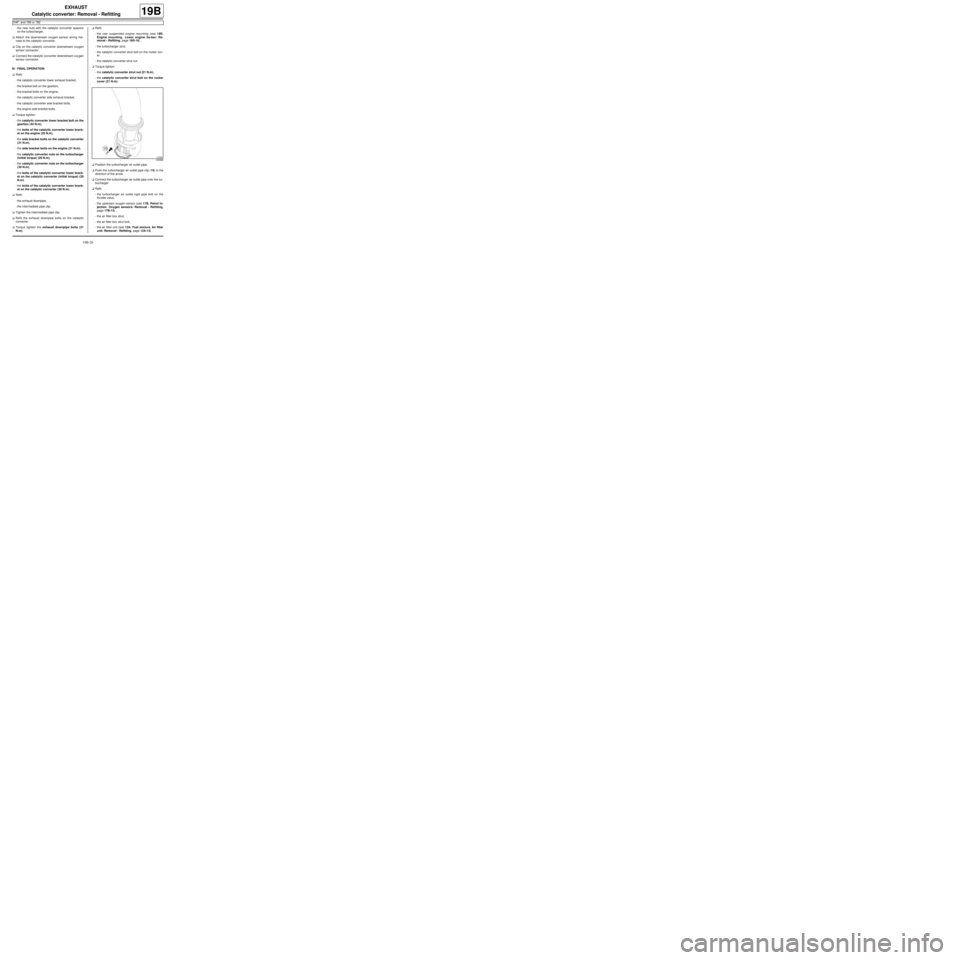
aPush the turbocharger air outlet pipe clip (15) in the
direction of the arrow.
aConnect the turbocharger air outlet pipe onto the tur-
bocharger.
aRefit:
-the turbocharger air outlet rigid pipe bolt on the
throttle valve,
-the upstream oxygen sensor (see 17B, Petrol in-
jection, Oxygen sensors: Removal - Refitting,
page 17B-13) ,
-the air filter box strut,
-the air filter box strut bolt,
-the air filter unit (see 12A, Fuel mixture, Air filter
unit: Removal - Refitting, page 12A-13) .
122666
Page 634 of 652
19D-4
ENGINE MOUNTING
Left-hand suspended engine mounting: Removal - Refitting
D4F or D7F
19D
REMOVAL
I - REMOVAL PREPARATION OPERATION
aPosition the vehicle on a two-post lift (see Vehicle:
Towing and lifting) (02A, Lifting equipment).
aRemove:
-the battery (see ) (80A, Battery),
-the battery tray (see Battery tray: Removal - Re-
fitting) (80A, Battery),
-the front left-hand wheel (see Wheel: Removal -
Refitting) (35A, Wheels and tyres),
-the petrol injection computer (see 17B, Petrol in-
jection, Petrol injection computer: Removal -
Refitting, page 17B-20) ,
-the petrol injection computer mounting bolts,
-the petrol injection computer mounting nuts.
aRemove:
-the engine wiring nut,
-the petrol injection computer mounting.
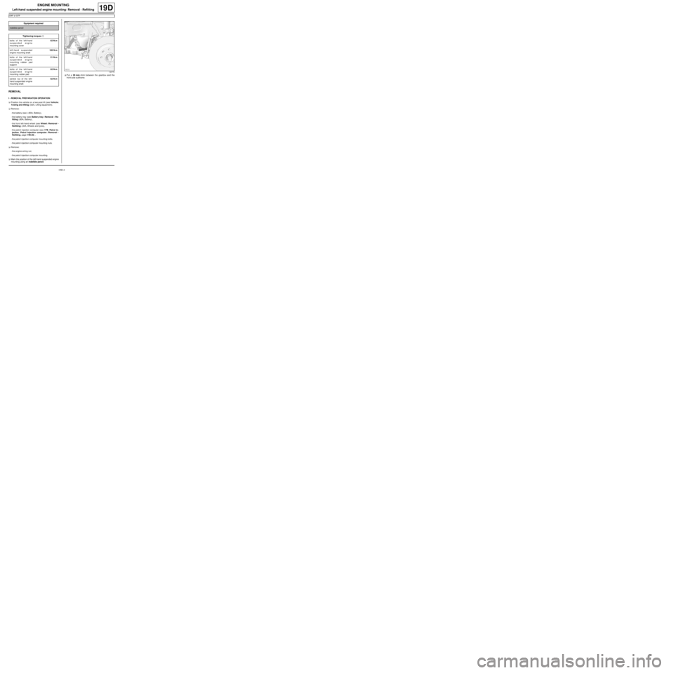
aMark the position of the left-hand suspended engine
mounting using an indelible pencil.aPut a 20 mm shim between the gearbox and the
front axle subframe. Equipment required
indelible pencil
Tightening torquesm
bolts of the left-hand
suspended engine
mounting cover62 N.m
left-hand suspended
engine mounting shaft105 N.m
bolts of the left-hand
suspended engine
mounting rubber pad
support21 N.m
bolts of the left-hand
suspended engine
mounting r ubber pad62 N.m
central nut of the left-
hand suspended engine
mounting shaft62 N.m
120778
Page 635 of 652
19D-5
ENGINE MOUNTING
Left-hand suspended engine mounting: Removal - Refitting
D4F or D7F
19D
II - OPERATION FOR REMOVAL OF PART
CONCERNED
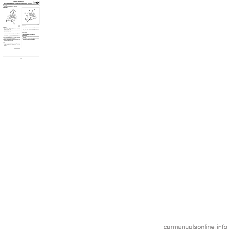
aRemove:
-the central nut (3) from the left-hand suspended
engine mounting shaft,
-the bolts (4) from the left-hand suspended engine
mounting rubber pad,
-the left-hand suspended engine mounting rubber
pad,
-the bolts (5) of the left-hand suspended engine
mounting rubber pad support.
aMove the wiring away from the left-hand suspended
engine mounting rubber pad support.
aRemove the rubber pad support from the left-hand
suspended engine mounting.
aRemove the electro-hydraulic unit (see Electro-hy-
draulic unit: Removal - Refitting) (21B, Sequential
gearbox).aRemove:
-the bolts (6) from the left-hand suspended engine
mounting cover,
-the cover from the left-hand suspended engine
mounting.
REFITTING
I - REFITTING OPERATION FOR PART
CONCERNED
aRefit the cover of the left-hand suspended engine
mounting.
aTorque tighten the bolts of the left-hand suspend-
ed engine mounting cover (62 N.m).
120310
JH1
120310
Page 636 of 652
19D-6
ENGINE MOUNTING
Left-hand suspended engine mounting: Removal - Refitting
D4F or D7F
19D
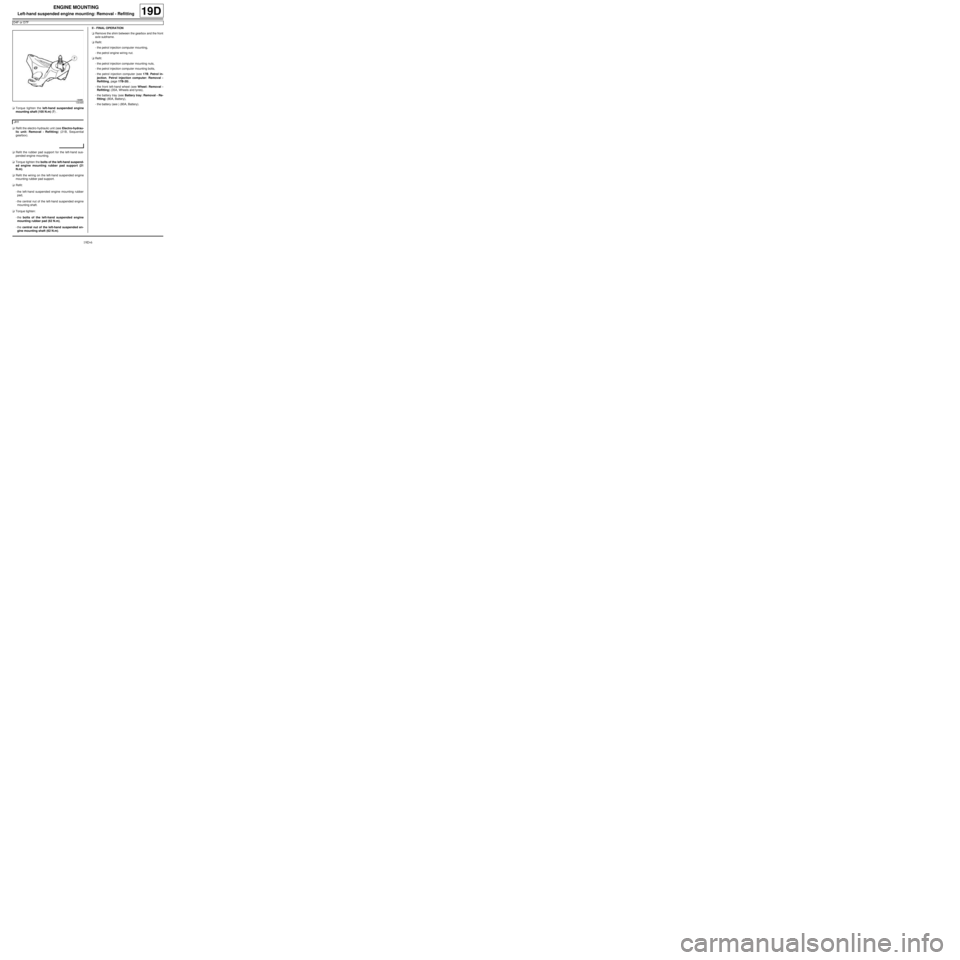
aTorque tighten the left-hand suspended engine
mounting shaft (105 N.m) (7) .
aRefit the electro-hydraulic unit (see Electro-hydrau-
lic unit: Removal - Refitting) (21B, Sequential
gearbox).
aRefit the rubber pad support for the left-hand sus-
pended engine mounting.
aTorque tighten the bolts of the left-hand suspend-
ed engine mounting rubber pad support (21
N.m).
aRefit the wiring on the left-hand suspended engine
mounting rubber pad support.
aRefit:
-the left-hand suspended engine mounting rubber
pad,
-the central nut of the left-hand suspended engine
mounting shaft.
aTorque tighten:
-the bolts of the left-hand suspended engine
mounting rubber pad (62 N.m),
-the central nut of the left-hand suspended en-
gine mounting shaft (62 N.m).II - FINAL OPERATION
aRemove the shim between the gearbox and the front
axle subframe.
aRefit:
-the petrol injection computer mounting,
-the petrol engine wiring nut.
aRefit:
-the petrol injection computer mounting nuts,
-the petrol injection computer mounting bolts,
-the petrol injection computer (see 17B, Petrol in-
jection, Petrol injection computer: Removal -
Refitting, page 17B-20) ,
-the front left-hand wheel (see Wheel: Removal -
Refitting) (35A, Wheels and tyres),
-the battery tray (see Battery tray: Removal - Re-
fitting) (80A, Battery),
-the battery (see ) (80A, Battery).
130485
JH1
Page 638 of 652
19D-8
ENGINE MOUNTING
Left-hand suspended engine mounting: Removal - Refitting
K9K
19D
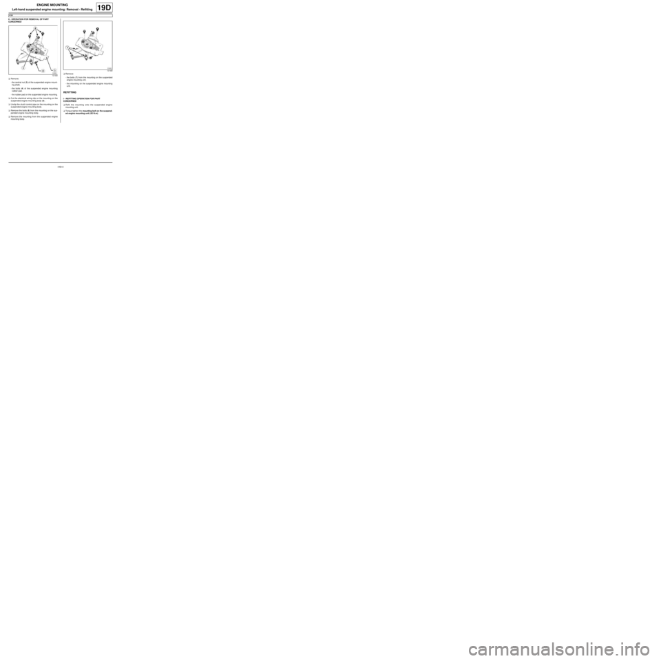
II - OPERATION FOR REMOVAL OF PART
CONCERNED
aRemove:
-the central nut (3) of the suspended engine mount-
ing shaft,
-the bolts (4) of the suspended engine mounting
rubber pad,
-the rubber pad on the suspended engine mounting.
aCut the electrical wiring clip on the mounting on the
suspended engine mounting body (5) .
aUnclip the clutch control pipe on the mounting on the
suspended engine mounting body.
aRemove the bolts (6) from the mounting on the sus-
pended engine mounting body.
aRemove the mounting from the suspended engine
mounting body.aRemove:
-the bolts (7) from the mounting on the suspended
engine mounting unit,
-the mounting on the suspended engine mounting
unit.
REFITTING
I - REFITTING OPERATION FOR PART
CONCERNED
aRefit the mounting onto the suspended engine
mounting unit.
aTorque tighten the mounting bolt on the suspend-
ed engine mounting unit ( 62 N.m).
121428
121428
Page 639 of 652
19D-9
ENGINE MOUNTING
Left-hand suspended engine mounting: Removal - Refitting
K9K
19D
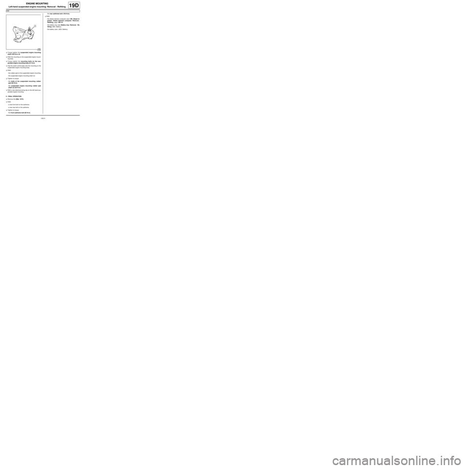
aTorque tighten the suspended engine mounting
shaft (105 N.m ) (8) .
aRefit the mounting on the suspended engine mount-
ing body.
aTorque tighten the mounting bolts on the sus-
pended engine mounting body (21 N.m).
aClip the clutch control pipe onto the mounting on the
suspended engine mounting body.
aRefit:
-the rubber pad on the suspended engine mounting,
-the suspended engine mounting shaft nut.
aTighten to torque:
-the bolts of the suspended mounting rubber
pad (62 N.m),
-the suspended engine mounting rubber pad
shaft nut (62 N.m).
aRefit a new electrical wiring clip on the left-hand sus-
pended engine mounting.
II - FINAL OPERATION
aRemove the (Mot. 1672).
aRefit:
-a new front bolt on the subframe,
-a new rear bolt on the subframe.
aTighten to torque:
-the front subframe bolt (62 N.m),-the rear subframe bolt (105 N.m).
aRefit:
-the diesel injection computer (see 13B, Diesel in-
jection, Diesel injection computer: Removal -
Refitting, page 13B-13) ,
-the battery tray (see Battery tray: Removal - Re-
fitting) (80A, Battery),
-the battery (see ) (80A, Battery).
130485
Page 641 of 652
19D-11
ENGINE MOUNTING
Left-hand suspended engine mounting: Removal - Refitting
K4M
19D
II - REMOVAL OPERATION
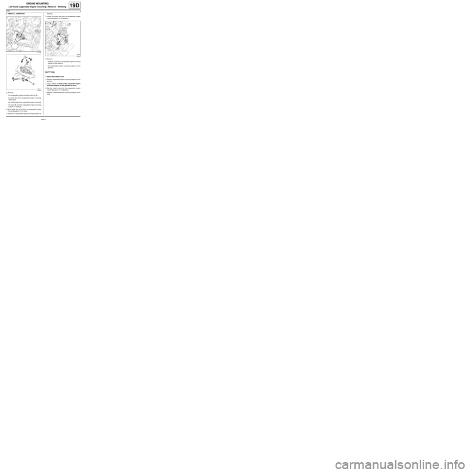
aRemove:
-the suspended engine mounting shaft nut (4) ,
-the bolts (5) of the suspended engine mounting
rubber pad,
-the rubber pad on the suspended engine mounting,
-the bolts (6) from the suspended engine mounting
support on the body.
aMove aside the wiring from the suspended engine
mounting support on the body.
aRemove the suspended engine mounting support onthe body.
aUnclip the clutch pipe from the suspended engine
mounting support on the gearbox.
aRemove:
-the bolts (7) from the suspended engine mounting
support on the gearbox,
-the suspended engine mounting support on the
gearbox.
REFITTING
I - REFITTING OPERATION
aRefit the suspended engine mounting support on the
gearbox.
aTorque tighten the bolts of the suspended engine
mounting support on the gearbox (62 N.m).
aClip the clutch pipe onto the suspended engine
mounting support on the gearbox.
aRefit the suspended engine mounting support on the
body.
131760
120310
132372
Page 642 of 652
19D-12
ENGINE MOUNTING
Left-hand suspended engine mounting: Removal - Refitting
K4M
19D
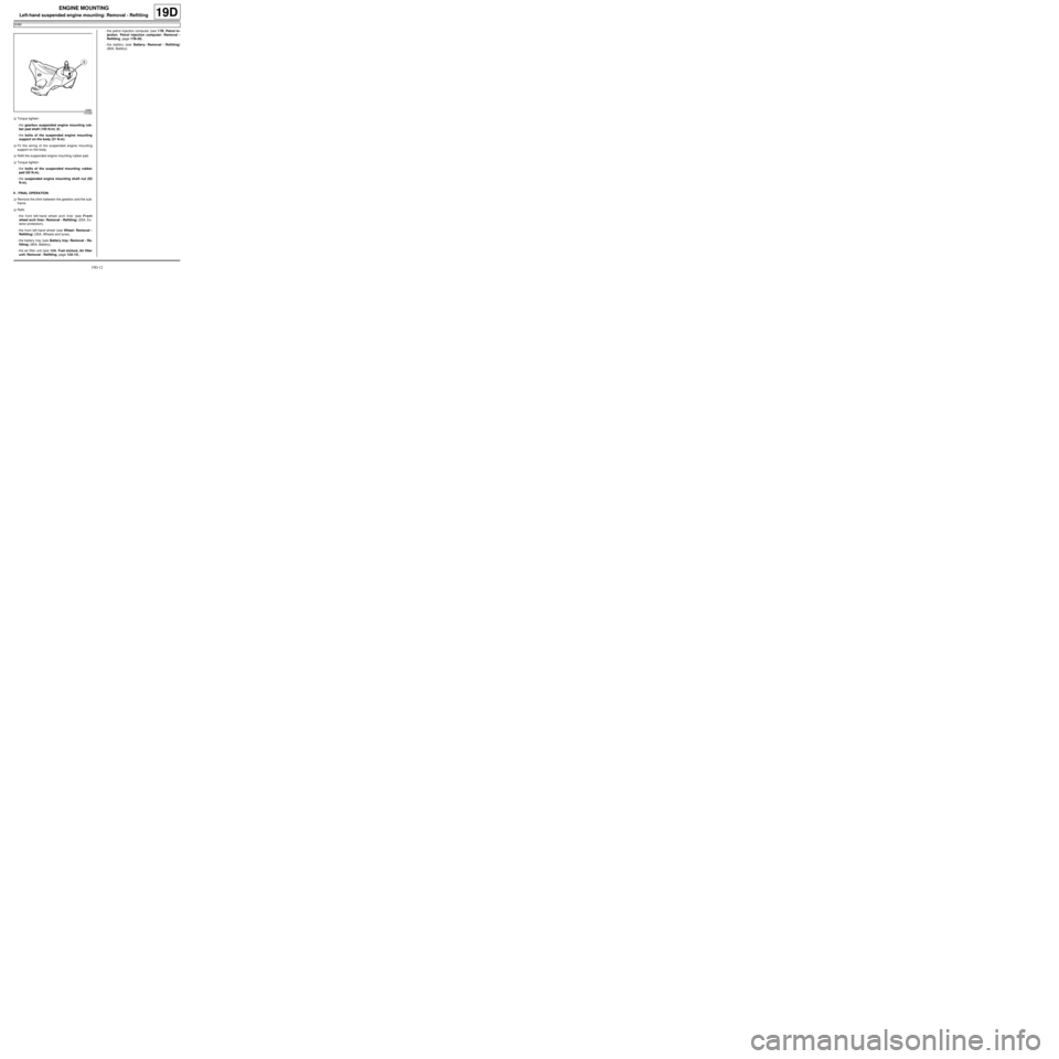
aTorque tighten:
-the gearbox suspended engine mounting rub-
ber pad shaft (105 N.m) (8) ,
-the bolts of the suspended engine mounting
support on the body (21 N.m).
aFit the wiring of the suspended engine mounting
support on the body.
aRefit the suspended engine mounting rubber pad.
aTorque tighten:
-the bolts of the suspended mounting rubber
pad (62 N.m),
-the suspended engine mounting shaft nut (62
N.m).
II - FINAL OPERATION
aRemove the shim between the gearbox and the sub-
frame.
aRefit:
-the front left-hand wheel arch liner (see Front
wheel arch liner: Removal - Refitting) (55A, Ex-
terior protection),
-the front left-hand wheel (see Wheel: Removal -
Refitting) (35A, Wheels and tyres),
-the battery tray (see Battery tray: Removal - Re-
fitting) (80A, Battery),
-the air filter unit (see 12A, Fuel mixture, Air filter
unit: Removal - Refitting, page 12A-13) ,-the petrol injection computer (see 17B, Petrol in-
jection, Petrol injection computer: Removal -
Refitting, page 17B-20) ,
-the battery (see Battery: Removal - Refitting)
(80A, Battery).
130485