drain bolt RENAULT TWINGO RS 2009 2.G Engine And Peripherals User Guide
[x] Cancel search | Manufacturer: RENAULT, Model Year: 2009, Model line: TWINGO RS, Model: RENAULT TWINGO RS 2009 2.GPages: 652
Page 49 of 652
10A-43
ENGINE AND CYLINDER BLOCK ASSEMBLY
Conrod bearing shell: Removal - Refitting
K9K
10A
II - REMOVAL - REFITTING OPERATIONS FOR THE
CON ROD BEARING SHELLS ON CYLINDERS
NO.3, 1 AND 4
aPerform the same removal - refitting operations as
for the con rod bearing shells on cylinder no. 2.
III - FINAL OPERATION
aparts always to be replaced: engine oil sump
seal
parts always to be replaced: Oil filter
parts always to be replaced: Drain plug seal on
engine oil sump
aUse a wooden spatula or an ABRASIVE PAD to
clean the joint face of the cylinder block and engine
oil sump.
aRefit the oil pump.
aFit without tightening the oil pump bolts, while keep-
ing a clearance of 3 mm to 5 mm.
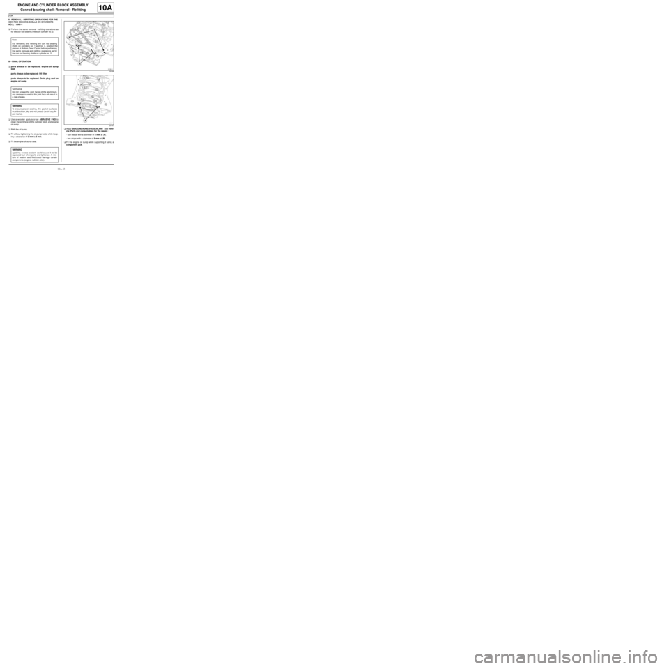
aFit the engine oil sump seal.aApply SILICONE ADHESIVE SEALANT (see Vehi-
cle: Parts and consumables for the repair) :
-four beads with a diameter of 5 mm at (A) ,
-two drops with a diameter of 5 mm at (B) .
aFit the engine oil sump while supporting it using a
component jack. Note:
For removing and refitting the con rod bearing
shells on cylinders no. 1 and no. 4, position the
pistons at Bottom Dead Centre before performing
the same removal and refitting operations as for
the con rod bearing shells on cylinder no. 2.
WARNING
Do not scrape the joint faces of the aluminium,
any damage caused to the joint face will result in
a risk of leaks.
WARNING
To ensure proper sealing, the gasket surfaces
must be clean, dry and not greasy (avoid any fin-
ger marks).
WARNING
Applying excess sealant could cause it to be
squeezed out when parts are tightened. A mix-
ture of sealant and fluid could damage certain
components (engine, radiator, etc.).
20166
20167
Page 50 of 652
10A-44
ENGINE AND CYLINDER BLOCK ASSEMBLY
Conrod bearing shell: Removal - Refitting
K9K
10A
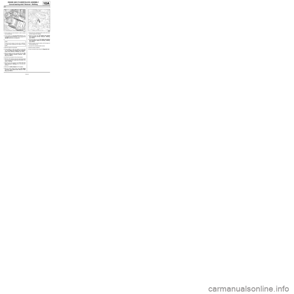
aTilt the engine oil sump forwards in order to access
the oil pump bolts.
aTorque tighten the oil pump bolts (25 N.m) using
the torque wrench PROSTEEL, part number 77 11
226 888 starting with the 13 mm bolt.
a
aRefit the engine oil sump bolts.
aTorque tighten in order the engine oil sump bolts
(see 10A, Engine and cylinder block assembly,
Lower cover: Removal - Refitting, page 10A-6) .
aRefit the catalytic converter upstream stay (see 19B,
Exhaust, Catalytic converter: Removal - Refit-
ting, page 19B-12) .
aConnect the connector to the oil level sensor.
aRefit the relay bearing of the front right-hand wheel
driveshaft (see Front right-hand driveshaft: Re-
moval - Refitting) .
aRefit the front axle subframe (see Front axle sub-
frame: Removal - Refitting) (31A, Front axle com-
ponents).
aRemove the safety strap(s) from the radiator.
aRefit the lower engine tie-bar (see 19D, Engine
mounting, Lower engine tie-bar: Removal - Refit-
ting, page 19D-18) .aDisconnect the crankshaft position sensor (4) to pre-
vent the engine from starting.
aRefit the oil filter (see 10A, Engine and cylinder
block assembly, Oil filter: Removal - Refitting,
page 10A-29)
aFill up the engine oil (see 10A, Engine and cylinder
block assembly, Engine oil: Draining - Refilling,
page 10A-22) .
aStart the engine using the starter until the engine oil
warning light goes out.
aConnect the crankshaft position sensor.
aRefit the engine undertray.
aClear the present faults using the Diagnostic tool.
140918
Note:
Check that the engine oil sump seal is definitely
in place before tightening the engine oil sump
bolts.
123824
Page 56 of 652
10A-50
ENGINE AND CYLINDER BLOCK ASSEMBLY
Oil pump: Removal - Refitting
K9K
10A
REMOVAL
I - OPERATION FOR REMOVAL OF PART
CONCERNED
aPosition the vehicle on a two-post lift ( (see Vehicle:
Towing and lifting) ).
aDisconnect the battery ( (see Battery: Removal -
Refitting) ).
aRemove the sump (see 10A, Engine and cylinder
block assembly, Lower cover: Removal - Refit-
ting, page 10A-6) .
II - OPERATION FOR REMOVAL OF PART
CONCERNED
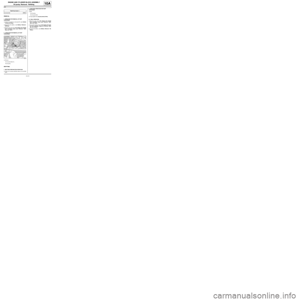
aRemove:
-the oil pump bolts (1) ,
-the oil pump.
REFITTING
I - REFITTING PREPARATION OPERATION
aCheck for oil pump centering rings on the cylinder
block.II - REFITTING OPERATION FOR PART
CONCERNED
aRefit:
-the oil pump,
-the oil pump bolts.
aTorque tighten the oil pump bolts (25 Nm).
III - FINAL OPERATION.
aRefit the sump (see 10A, Engine and cylinder
block assembly, Lower cover: Removal - Refit-
ting, page 10A-6) .
aTop up the engine oil (see 10A, Engine and cylin-
der block assembly, Engine oil: Draining - Refill-
ing, page 10A-22) .
aConnect the battery ( (see Battery: Removal - Re-
fitting) ). Tightening torquesm
oil pump bolts25 Nm
120313
Page 57 of 652
10A-51
ENGINE AND CYLINDER BLOCK ASSEMBLY
Oil pump: Removal - Refitting
D4F or D7F
10A
REMOVAL
I - REMOVAL PREPARATION OPERATION
aPosition the vehicle on a two-post lift (see Vehicle:
Towing and lifting) (02A, Lifting equipment).
aDrain the engine oil (see 10A, Engine and cylinder
block assembly, Engine oil: Draining - Refilling,
page 10A-22) .
aRemove:
-the oil filter (see 10A, Engine and cylinder block
assembly, Oil filter: Removal - Refitting, page
10A-29) ,
-the dipstick,
-the front wheels (see Wheel: Removal - Refitting)
(35A, Wheels and tyres),
-the front wheel arch liners (see Front wheel arch
liner: Removal - Refitting) (55A, Exterior protec-
tion),
-the accessories belt (see 11A, Top and front of
engine, Accessories belt: Removal - Refitting,
page 11A-3) ,
-the engine tie-bar (see 19D, Engine mounting,
Lower engine tie-bar: Removal - Refitting, page
19D-18) ,
-the right-hand suspended engine mounting (see
19D, Engine mounting, Right-hand suspended
engine mounting: Removal - Refitting, page
19D-13) ,-the crankshaft accessories pulley (see 11A, Top
and front of engine, Crankshaft accessories
pulley: Removal - Refitting, page 11A-20) ,
-the timing belt (see 11A, Top and front of engine,
Timing belt: Removal - Refitting, page 11A-27) .
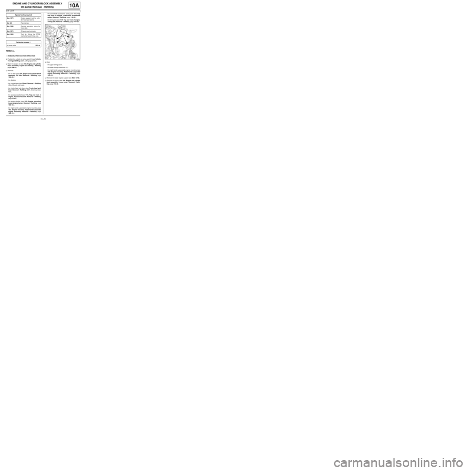
aRefit:
-the upper timing cover,
-the upper timing cover bolts (1) ,
-the right-hand suspended engine mounting (see
19D, Engine mounting, Right-hand suspended
engine mounting: Removal - Refitting, page
19D-13) .
aRemove the lower engine support tool (Mot. 1379).
aRemove the sump (see 10A, Engine and cylinder
block assembly, Lower cover: Removal - Refit-
ting, page 10A-6) . Special tooling required
Mot. 1379Engine suppor t tool for cylin-
der head oper ations.
Ms. 583Pipe clamps .
Mot. 1448Remote operation pliers for
hose clips .
Mot. 1374Oil pump seal e xtractor.
Mot. 1626Tool for fitting the PTFE
cr ankshaft seal, timing end.
Tightening torquesm
oil pump bolts10 N.m
109740
Page 62 of 652
10A-56
ENGINE AND CYLINDER BLOCK ASSEMBLY
Oil pump: Removal - Refitting
D4F or D7F
10A
aRemove:
-the nut,
-the cover,
-the guard,
-the threaded rod.
aConnect the oil-coolant heat exchanger hoses.
aPut the clips (3) in place using the (Mot. 1448).
aRemove the hose clamps (Ms. 583) from the oil-wa-
ter heat exchanger hoses.
aConnect the oil pressure sensor connector.
aRefit:
-the timing sprocket,
-the sump (see 10A, Engine and cylinder block
assembly, Lower cover: Removal - Refitting,
page 10A-6) .
aFit the lower engine support tool (Mot. 1379).
aRemove:
-the right-hand suspended mounting support bolts,
-the right-hand suspended mounting support,
-the upper timing cover bolts,
-the upper timing cover.aRefit:
-the timing belt (see 11A, Top and front of engine,
Timing belt: Removal - Refitting, page 11A-27) ,
-the crankshaft accessories pulley (see 11A, Top
and front of engine, Crankshaft accessories
pulley: Removal - Refitting, page 11A-20) ,
-the right-hand suspended engine mounting (see
19D, Engine mounting, Right-hand suspended
engine mounting: Removal - Refitting, page
19D-13) .
aRemove the lower engine support tool (Mot. 1379).
aRefit:
-the engine tie-bar (see 19D, Engine mounting,
Lower engine tie-bar: Removal - Refitting, page
19D-18) ,
-the accessories belt (see 11A, Top and front of
engine, Accessories belt: Removal - Refitting,
page 11A-3) ,
-the engine undertray,
-the front wheel arch liners (see Front wheel arch
liner: Removal - Refitting) (55A, Exterior protec-
tion),
-the front wheels (see Wheel: Removal - Refitting)
(35A, Wheels and tyres),
-the dipstick,
-the oil filter (see 10A, Engine and cylinder block
assembly, Oil filter: Removal - Refitting, page
10A-29) .
aTop up the engine oil (see 10A, Engine and cylin-
der block assembly, Engine oil: Draining - Refill-
ing, page 10A-22) .
aTop up the coolant level (see 19A, Cooling, Cool-
ing system: Draining - Refilling, page 19A-9) .
20779
D4F, and 780 or 782
Page 63 of 652
10A-57
ENGINE AND CYLINDER BLOCK ASSEMBLY
Oil pump: Removal - Refitting
K4M
10A
REMOVAL
I - REMOVAL PREPARATION OPERATION
aPosition the vehicle on a two-post lift (see Vehicle:
Towing and lifting) (02A, Lifting equipment).
aRemove:
-the front wheels (see Wheel: Removal - Refitting)
(35A, Wheels and tyres),
-the engine undertray.
aDrain the engine oil (see 10A, Engine and cylinder
block assembly, Engine oil: Draining - Refilling,
page 10A-22) .
aRemove:
-the front wheel arch liners (see Front wheel arch
liner: Removal - Refitting) (55A, Exterior protec-
tion),
-the front bumper (see Front bumper: Removal -
Refitting) (55A, Exterior protection),
-the rear engine tie-bar (see 19D, Engine mount-
ing, Lower engine tie-bar: Removal - Refitting,
page 19D-18) ,
-the front axle subframe (see Front axle subframe:
Removal - Refitting) (31A, Front axle compo-
nents).
aRemove the sump (see 10A, Engine and cylinder
block assembly, Lower cover: Removal - Refit-
ting, page 10A-6) .II - REMOVAL OPERATION
aRemove:
-the oil pump bolts (1) ,
-the oil pump.
REFITTING
I - REFITTING OPERATION
aPosition the oil pump pinion on the chain.
aRefit the oil pump.
aTorque tighten the oil pump bolts (25 N.m).
II - FINAL OPERATION
aRefit the sump (see 10A, Engine and cylinder
block assembly, Lower cover: Removal - Refit-
ting, page 10A-6) .
aRefit:
-the front axle subframe (see Front axle subframe:
Removal - Refitting) (31A, Front axle compo-
nents),
-the rear engine tie-bar (see 19D, Engine mount-
ing, Lower engine tie-bar: Removal - Refitting,
page 19D-18) ,
-the front bumper (see Front bumper: Removal -
Refitting) (55A, Exterior protection),
-the front wheel arch liners (see Front wheel arch
liner: Removal - Refitting) (55A, Exterior protec-
tion), Tightening torquesm
oil pump bolts25 N.m
128799
Page 69 of 652
10A-63
ENGINE AND CYLINDER BLOCK ASSEMBLY
Multifunction support: Removal - Refitting
K9K, and AIR CONDITIONING
10A
REMOVAL
I - REMOVAL PREPARATION OPERATION
aPosition the vehicle on a two-post lift ( (see Vehicle:
Towing and lifting) ).
aDisconnect the battery ( (see Battery: Removal -
Refitting) ).
aRemove:
-the engine cover,
-the front wheels, (see Wheel: Removal - Refit-
ting)
-the front wheel arch liners ( (see Front wheel arch
liner: Removal - Refitting) ),
-the front bumper ( (see Front bumper: Removal -
Refitting) ),
-the accessories belt (see 11A, Top and front of
engine, Accessories belt: Removal - Refitting,
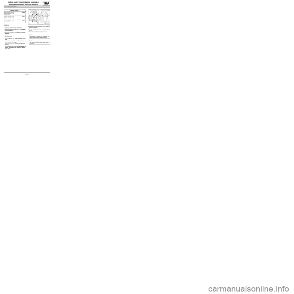
page 11A-3) .aDisconnect the clutch connector (1) from the air con-
ditioning compressor.
aRemove the bolts (2) from the air conditioning com-
pressor.
aMove the air conditioning compressor aside. Tightening torquesm
bolts mounting the mul-
tifunction support on the
cylinder block44 N.m
bolt mounting the multi-
function support on the
sump25 N.m
air conditioning com-
pressor bolts21 N.m
108866
Note:
Take care not to constrain the compressor con-
necting pipes to prevent refrigerant leaking.
Note:
This operation does not require the AC system to
be drained.
Page 77 of 652
10A-71
ENGINE AND CYLINDER BLOCK ASSEMBLY
Multifunction support: Removal - Refitting
K4M
10A
REMOVAL
I - REMOVAL PREPARATION OPERATION
aPosition the vehicle on a two-post lift (see Vehicle:
Towing and lifting) (02A, Lifting equipment).
aDisconnect the battery (see Battery: Removal - Re-
fitting) (80A, Battery).
aRemove the engine undertray.
aDrain the refrigerant circuit using a refrigerant
charging station (see Refrigerant circuit: Drain-
ing - Filling) (62A, Air conditioning).
aRemove:
-the front right-hand wheel (see Wheel: Removal -
Refitting) (35A, Wheels and tyres),
-the front right-hand wheel arch liner (see Front
wheel arch liner: Removal - Refitting) (55A, Ex-
terior protection),
-the front bumper (see Front bumper: Removal -
Refitting) (55A, Exterior protection),
-the headlights (see Halogen headlight: Removal
- Refitting) (80B, Headlights),
-the bonnet catch (see Bonnet lock: Removal -
Refitting) (52A, Non-side opening element mecha-
nisms),-the front upper cross member (see Front upper
cross member: Removal - Refitting) (42A, Upper
front structure),
-the accessories belt (see 11A, Top and front of
engine, Accessories belt: Removal - Refitting,
page 11A-3) ,
-the alternator (see 16A, Starting - Charging, Al-
ternator: Removal - Refitting, page 16A-1) ,
-the air conditioning compressor (see Compressor:
Removal - Refitting) (62A, Air conditioning). Equipment required
refrigerant charging station
Tightening torquesm
multifunction support
bolts 1 and 2 (initial
torque)5 N.m
multifunction support
bolt 7 on the cylinder
block (initial torque)5 N.m
multifunction support
bolts 6, 5, 4 and 35 N.m
multifunction support
bolts44 N.m
multifunction support
bolt on the cylinder
block25 N.m
Page 79 of 652
10A-73
ENGINE AND CYLINDER BLOCK ASSEMBLY
Multifunction support: Removal - Refitting
K4M
10A
REFITTING
I - REFITTING OPERATION
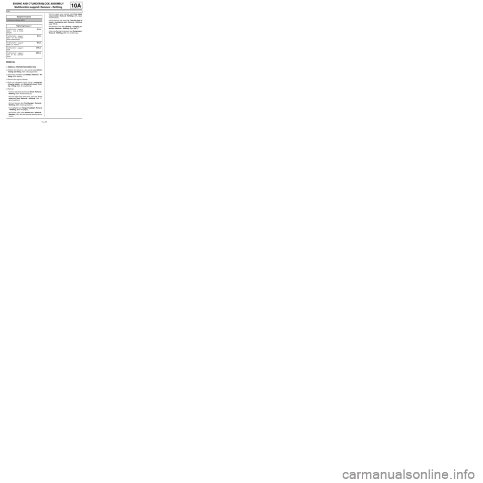
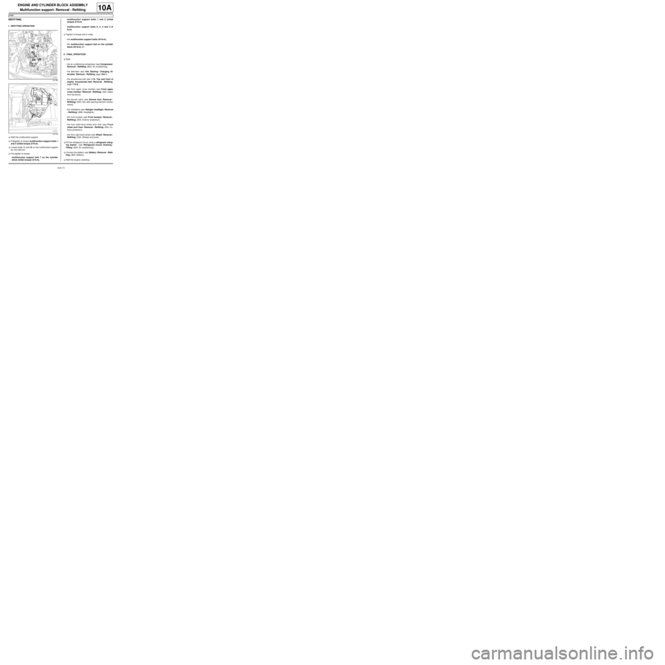
aRefit the multifunction support.
aPretighten to torque multifunction support bolts 1
and 2 (initial torque) (5 N.m).
aLoosen bolts (1) and (2) on the multifunction support
by one half-turn.
aPre-tighten to torque:
-multifunction support bolt 7 on the cylinder
block (initial torque) (5 N.m),-multifunction support bolts 1 and 2 (initial
torque) (5 N.m),
-multifunction support bolts 6, 5, 4 and 3 (5
N.m).
aTighten to torque and in order:
-the multifunction support bolts (44 N.m),
-the multifunction support bolt on the cylinder
block (25 N.m) (7) .
II - FINAL OPERATION
aRefit:
-the air conditioning compressor (see Compressor:
Removal - Refitting) (62A, Air conditioning),
-the alternator (see 16A, Starting - Charging, Al-
ternator: Removal - Refitting, page 16A-1) ,
-the accessories belt (see 11A, Top and front of
engine, Accessories belt: Removal - Refitting,
page 11A-3) ,
-the front upper cross member (see Front upper
cross member: Removal - Refitting) (42A, Upper
front structure),
-the bonnet catch (see Bonnet lock: Removal -
Refitting) (52A, Non-side opening element mecha-
nisms),
-the headlights (see Halogen headlight: Removal
- Refitting) (80B, Headlights),
-the front bumper (see Front bumper: Removal -
Refitting) (55A, Exterior protection),
-the front right-hand wheel arch liner (see Front
wheel arch liner: Removal - Refitting) (55A, Ex-
terior protection),
-the front right-hand wheel (see Wheel: Removal -
Refitting) (35A, Wheels and tyres).
aFill the refrigerant circuit using a refrigerant charg-
ing station (see Refrigerant circuit: Draining -
Filling) (62A, Air conditioning).
aConnect the battery (see Battery: Removal - Refit-
ting) (80A, Battery).
aRefit the engine undertray.
131780
131779
Page 83 of 652
10A-77
ENGINE AND CYLINDER BLOCK ASSEMBLY
Engine - gearbox assembly: Removal - Refitting
D4F or D7F
10A
a
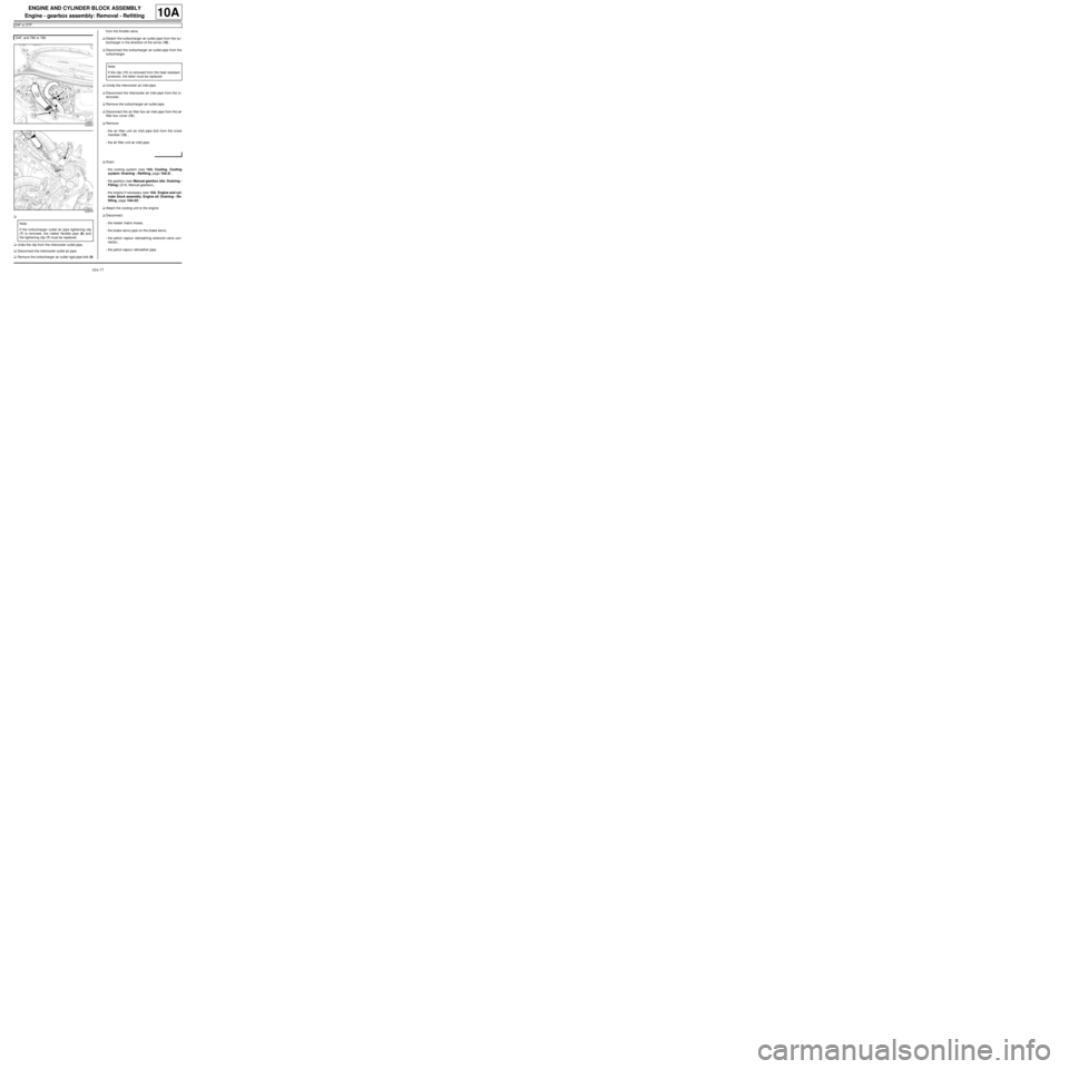
aUndo the clip from the intercooler outlet pipe.
aDisconnect the intercooler outlet air pipe.
aRemove the turbocharger air outlet rigid pipe bolt (9)from the throttle valve.
aDetach the turbocharger air outlet pipe from the tur-
bocharger in the direction of the arrow (10) .
aDisconnect the turbocharger air outlet pipe from the
turbocharger.
aUnclip the intercooler air inlet pipe.
aDisconnect the intercooler air inlet pipe from the in-
tercooler.
aRemove the turbocharger air outlet pipe.
aDisconnect the air filter box air inlet pipe from the air
filter box cover (12) .
aRemove:
-the air filter unit air inlet pipe bolt from the cross
member (13) ,
-the air filter unit air inlet pipe.
aDrain:
-the cooling system (see 19A, Cooling, Cooling
system: Draining - Refilling, page 19A-9) ,
-the gearbox (see Manual gearbox oils: Draining -
Filling) (21A, Manual gearbox),
-the engine if necessary (see 10A, Engine and cyl-
inder block assembly, Engine oil: Draining - Re-
filling, page 10A-22) .
aAttach the cooling unit to the engine.
aDisconnect:
-the heater matrix hoses,
-the brake servo pipe on the brake servo,
-the petrol vapour rebreathing solenoid valve con-
nector,
-the petrol vapour rebreather pipe. D4F, and 780 or 782
122833
122673
Note:
If the turbocharger outlet air pipe tightening clip
(7) is removed, the rubber flexible pipe (8) and
the tightening clip (7) must be replaced.
Note:
If the clip (11) is removed from the heat resistant
protector, the latter must be replaced.