wheel bolt torque RENAULT TWINGO RS 2009 2.G Engine And Peripherals User Guide
[x] Cancel search | Manufacturer: RENAULT, Model Year: 2009, Model line: TWINGO RS, Model: RENAULT TWINGO RS 2009 2.GPages: 652
Page 69 of 652
10A-63
ENGINE AND CYLINDER BLOCK ASSEMBLY
Multifunction support: Removal - Refitting
K9K, and AIR CONDITIONING
10A
REMOVAL
I - REMOVAL PREPARATION OPERATION
aPosition the vehicle on a two-post lift ( (see Vehicle:
Towing and lifting) ).
aDisconnect the battery ( (see Battery: Removal -
Refitting) ).
aRemove:
-the engine cover,
-the front wheels, (see Wheel: Removal - Refit-
ting)
-the front wheel arch liners ( (see Front wheel arch
liner: Removal - Refitting) ),
-the front bumper ( (see Front bumper: Removal -
Refitting) ),
-the accessories belt (see 11A, Top and front of
engine, Accessories belt: Removal - Refitting,
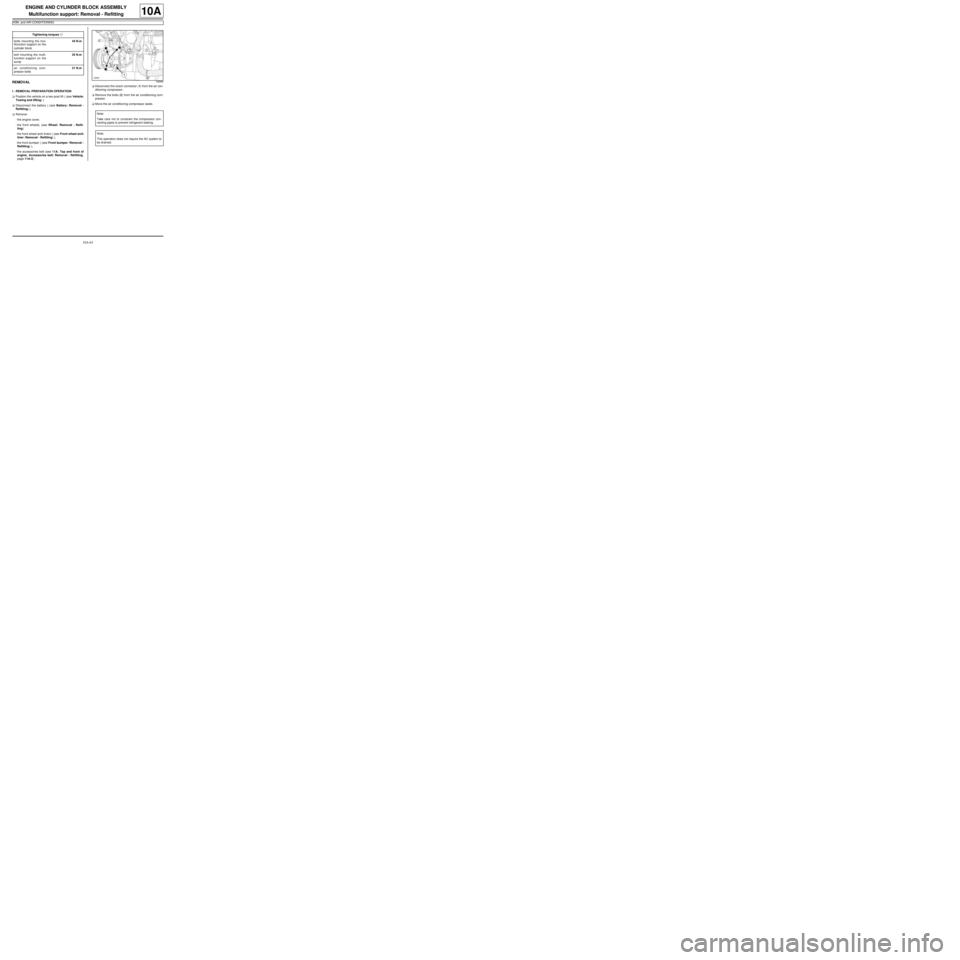
page 11A-3) .aDisconnect the clutch connector (1) from the air con-
ditioning compressor.
aRemove the bolts (2) from the air conditioning com-
pressor.
aMove the air conditioning compressor aside. Tightening torquesm
bolts mounting the mul-
tifunction support on the
cylinder block44 N.m
bolt mounting the multi-
function support on the
sump25 N.m
air conditioning com-
pressor bolts21 N.m
108866
Note:
Take care not to constrain the compressor con-
necting pipes to prevent refrigerant leaking.
Note:
This operation does not require the AC system to
be drained.
Page 70 of 652
10A-64
ENGINE AND CYLINDER BLOCK ASSEMBLY
Multifunction support: Removal - Refitting
K9K, and AIR CONDITIONING
10A
II - OPERATION FOR REMOVAL OF PART
CONCERNED
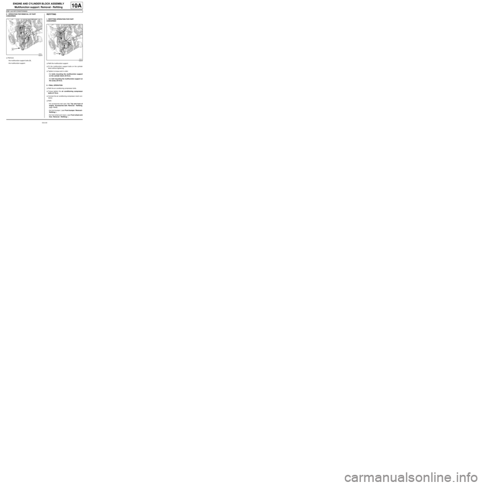
aRemove:
-the multifunction support bolts (3) ,
-the multifunction support.REFITTING
I - REFITTING OPERATION FOR PART
CONCERNED
aRefit the multifunction support.
aFit the multifunction support bolts on the cylinder
block without tightening.
aTighten to torque and in order:
-the bolts mounting the multifunction support
on the cylinder block (44 N.m),
-the bolt mounting the multifunction support on
the sump (25 N.m).
II - FINAL OPERATION
aRefit the air conditioning compressor bolts.
aTorque tighten the air conditioning compressor
bolts (21 N.m).
aConnect the air conditioning compressor clutch con-
nector.
aRefit:
-the accessories belt (see 11A, Top and front of
engine, Accessories belt: Removal - Refitting,
page 11A-3) ,
-the front bumper ( (see Front bumper: Removal -
Refitting) ),
-the front wheel arch liners ( (see Front wheel arch
liner: Removal - Refitting) ),
120315
120315
Page 73 of 652
10A-67
ENGINE AND CYLINDER BLOCK ASSEMBLY
Multifunction support: Removal - Refitting
D4F, and 772, and AIR CONDITIONING – D7F, and AIR CONDITIONING
10A
REMOVAL
I - REMOVAL PREPARATION OPERATION
aPosition the vehicle on a two-post lift (see Vehicle:
Towing and lifting) (02A, Lifting equipment).
aDisconnect the battery (see Battery: Removal - Re-
fitting) (80A, Battery).
aRemove:
-the front right-hand wheel (see Wheel: Removal -
Refitting) (35A, Wheels and tyres),
-the accessories belt (see 11A, Top and front of
engine, Accessories belt: Removal - Refitting,
page 11A-3) ,
-the alternator (see 16A, Starting - Charging, Al-
ternator: Removal - Refitting, page 16A-1) ,
-the air conditioning compressor (see Compressor:
Removal - Refitting) (62A, Air conditioning).
II - OPERATION FOR REMOVAL OF PART
CONCERNED
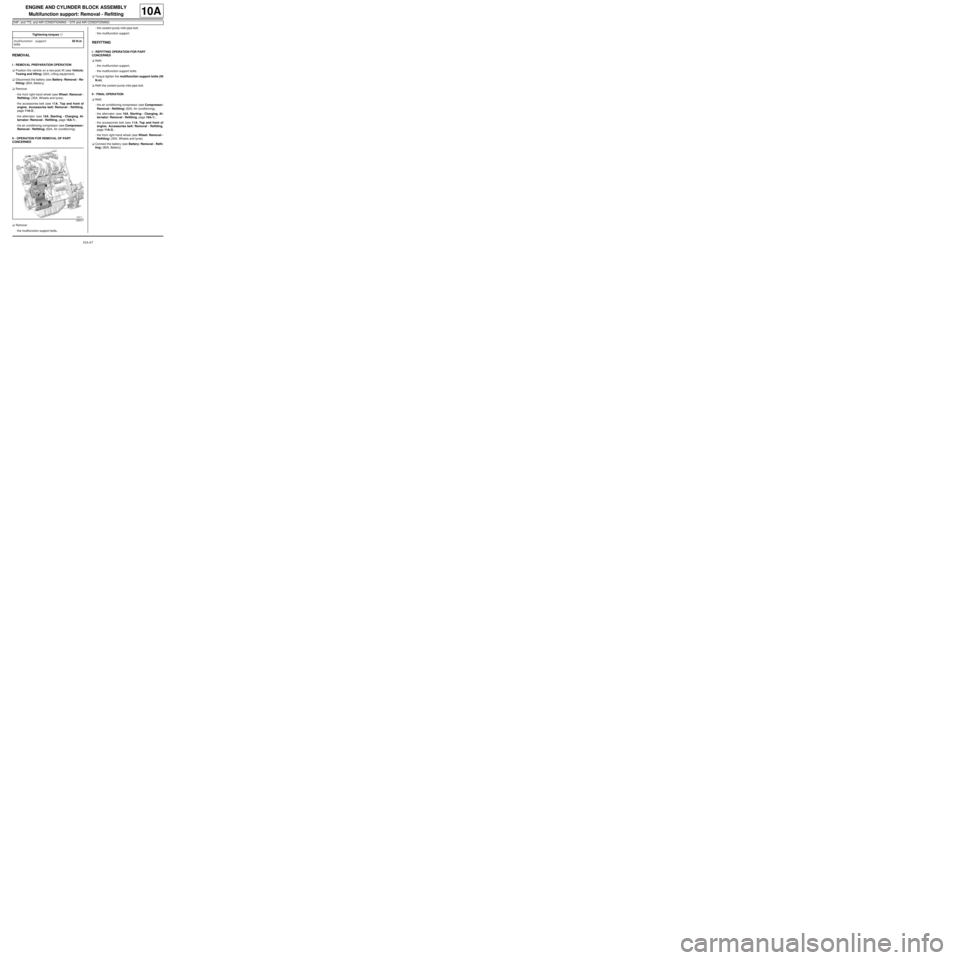
aRemove:
-the multifunction support bolts,-the coolant pump inlet pipe bolt,
-the multifunction support.
REFITTING
I - REFITTING OPERATION FOR PART
CONCERNED
aRefit:
-the multifunction support,
-the multifunction support bolts.
aTorque tighten the multifunction support bolts (50
N.m).
aRefit the coolant pump inlet pipe bolt.
II - FINAL OPERATION
aRefit:
-the air conditioning compressor (see Compressor:
Removal - Refitting) (62A, Air conditioning),
-the alternator (see 16A, Starting - Charging, Al-
ternator: Removal - Refitting, page 16A-1) ,
-the accessories belt (see 11A, Top and front of
engine, Accessories belt: Removal - Refitting,
page 11A-3) ,
-the front right-hand wheel (see Wheel: Removal -
Refitting) (35A, Wheels and tyres).
aConnect the battery (see Battery: Removal - Refit-
ting) (80A, Battery). Tightening torquesm
multifunction support
bolts50 N.m
120517
Page 75 of 652
10A-69
ENGINE AND CYLINDER BLOCK ASSEMBLY
Multifunction support: Removal - Refitting
D4F, and 780 or 782
10A
REMOVAL
I - REMOVAL PREPARATION OPERATION
aPosition the vehicle on a two-post lift (see Vehicle:
Towing and lifting) (02A, Lifting equipment).
aDisconnect the battery (see ) (80A, Battery).
aRemove:
-the front right-hand wheel (see Wheel: Removal -
Refitting) (35A, Wheels and tyres),
-the front right-hand wheel arch liner (see Front
wheel arch liner: Removal - Refitting) (55A, Ex-
terior protection),
-the accessories belt (see 11A, Top and front of
engine, Accessories belt: Removal - Refitting,
page 11A-3) ,
-the alternator (see 16A, Starting - Charging, Al-
ternator: Removal - Refitting, page 16A-1) .
aRemove the air conditioning compressor (see Com-
pressor: Removal - Refitting) (62A, Air condition-
ing).II - OPERATION FOR REMOVAL OF PART
CONCERNED
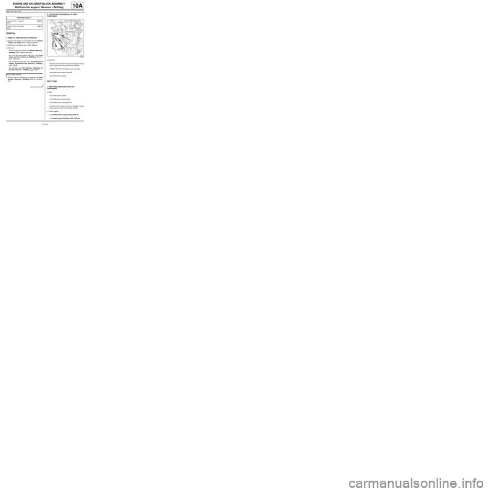
aRemove:
-the bolt of the coolant-oil heat exchanger cooling
pipes support from the multifunction support,
-the bolts (4) from the coolant pump inlet pipe,
-the multifunction support bolts (3) ,
-the multifunction support.
REFITTING
I - REFITTING OPERATION FOR PART
CONCERNED
aRefit:
-the multifunction support,
-the multifunction support bolts,
-the coolant pump inlet pipe bolts,
-the bolt of the coolant-oil heat exchanger cooling
pipes support on the multifunction support.
aTorque tighten:
-the multifunction support bolts (50 N.m),
-the coolant pump inlet pipe bolts (10 N.m). Tightening torquesm
multifunction support
bolts50 N.m
coolant pump inlet pipe
bolts10 N.m
AIR CONDITIONING
120956
Page 77 of 652
10A-71
ENGINE AND CYLINDER BLOCK ASSEMBLY
Multifunction support: Removal - Refitting
K4M
10A
REMOVAL
I - REMOVAL PREPARATION OPERATION
aPosition the vehicle on a two-post lift (see Vehicle:
Towing and lifting) (02A, Lifting equipment).
aDisconnect the battery (see Battery: Removal - Re-
fitting) (80A, Battery).
aRemove the engine undertray.
aDrain the refrigerant circuit using a refrigerant
charging station (see Refrigerant circuit: Drain-
ing - Filling) (62A, Air conditioning).
aRemove:
-the front right-hand wheel (see Wheel: Removal -
Refitting) (35A, Wheels and tyres),
-the front right-hand wheel arch liner (see Front
wheel arch liner: Removal - Refitting) (55A, Ex-
terior protection),
-the front bumper (see Front bumper: Removal -
Refitting) (55A, Exterior protection),
-the headlights (see Halogen headlight: Removal
- Refitting) (80B, Headlights),
-the bonnet catch (see Bonnet lock: Removal -
Refitting) (52A, Non-side opening element mecha-
nisms),-the front upper cross member (see Front upper
cross member: Removal - Refitting) (42A, Upper
front structure),
-the accessories belt (see 11A, Top and front of
engine, Accessories belt: Removal - Refitting,
page 11A-3) ,
-the alternator (see 16A, Starting - Charging, Al-
ternator: Removal - Refitting, page 16A-1) ,
-the air conditioning compressor (see Compressor:
Removal - Refitting) (62A, Air conditioning). Equipment required
refrigerant charging station
Tightening torquesm
multifunction support
bolts 1 and 2 (initial
torque)5 N.m
multifunction support
bolt 7 on the cylinder
block (initial torque)5 N.m
multifunction support
bolts 6, 5, 4 and 35 N.m
multifunction support
bolts44 N.m
multifunction support
bolt on the cylinder
block25 N.m
Page 79 of 652
10A-73
ENGINE AND CYLINDER BLOCK ASSEMBLY
Multifunction support: Removal - Refitting
K4M
10A
REFITTING
I - REFITTING OPERATION
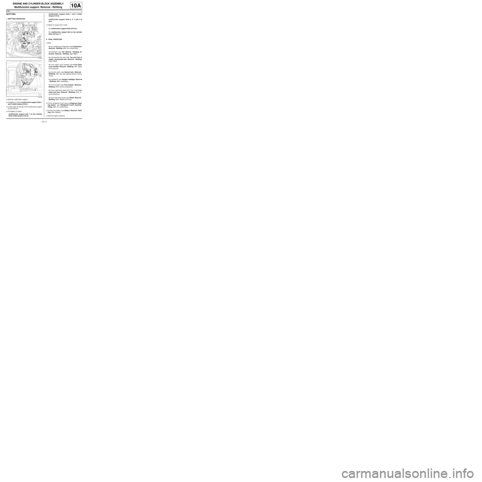
aRefit the multifunction support.
aPretighten to torque multifunction support bolts 1
and 2 (initial torque) (5 N.m).
aLoosen bolts (1) and (2) on the multifunction support
by one half-turn.
aPre-tighten to torque:
-multifunction support bolt 7 on the cylinder
block (initial torque) (5 N.m),-multifunction support bolts 1 and 2 (initial
torque) (5 N.m),
-multifunction support bolts 6, 5, 4 and 3 (5
N.m).
aTighten to torque and in order:
-the multifunction support bolts (44 N.m),
-the multifunction support bolt on the cylinder
block (25 N.m) (7) .
II - FINAL OPERATION
aRefit:
-the air conditioning compressor (see Compressor:
Removal - Refitting) (62A, Air conditioning),
-the alternator (see 16A, Starting - Charging, Al-
ternator: Removal - Refitting, page 16A-1) ,
-the accessories belt (see 11A, Top and front of
engine, Accessories belt: Removal - Refitting,
page 11A-3) ,
-the front upper cross member (see Front upper
cross member: Removal - Refitting) (42A, Upper
front structure),
-the bonnet catch (see Bonnet lock: Removal -
Refitting) (52A, Non-side opening element mecha-
nisms),
-the headlights (see Halogen headlight: Removal
- Refitting) (80B, Headlights),
-the front bumper (see Front bumper: Removal -
Refitting) (55A, Exterior protection),
-the front right-hand wheel arch liner (see Front
wheel arch liner: Removal - Refitting) (55A, Ex-
terior protection),
-the front right-hand wheel (see Wheel: Removal -
Refitting) (35A, Wheels and tyres).
aFill the refrigerant circuit using a refrigerant charg-
ing station (see Refrigerant circuit: Draining -
Filling) (62A, Air conditioning).
aConnect the battery (see Battery: Removal - Refit-
ting) (80A, Battery).
aRefit the engine undertray.
131780
131779
Page 80 of 652
10A-74
ENGINE AND CYLINDER BLOCK ASSEMBLY
Engine - gearbox assembly: Removal - Refitting
D4F or D7F
10A
REMOVAL
I - REMOVAL PREPARATION OPERATION
aPosition the vehicle on a two-post lift (see Vehicle:
Towing and lifting) (02A, Lifting equipment).
aRemove:
-the battery (see ) (80A, Battery),
-the battery tray (see Battery tray: Removal - Re-
fitting) (80A, Battery),
-the injection computer (see 17B, Petrol injection,
Petrol injection computer: Removal - Refitting,
page 17B-20) ,
-the computer mounting bolts,
-the computer mounting nuts,
-the computer mounting,
-the front wheels (see Wheel: Removal - Refitting)
(35A, Wheels and tyres),
-the front wheel arch liners (see Front wheel arch
liner: Removal - Refitting) (55A, Exterior protec-
tion).
-the front bumper (see Front bumper: Removal -
Refitting) (55A, Exterior protection),
-the engine compartment connection unit cover
bolts,
-the cover of the engine compartment connection
unit. Special tooling required
Tav. 476Ball joint extractor.
Ms. 583Pipe clamps .
Mot. 1379Engine suppor t tool for cylin-
der head oper ations.
Mot. 1390Suppor t for removal - refitting
of engine - gearbox assembly
Tav. 1233-01Tooling for carrying out opera-
tions on the axle subframe.
Equipment required
flywheel immobiliser
Tightening torquesm
front subframe bolts62 N.m
rear subframe bolts105 N.m
subframe rear tie rod
inner bolts21 N.m
subframe rear tie rod
outer bolts90 N.m
engine tie-bar bolts on
the gearbox105 N.m
engine tie-bar bolt on
the subframe105 N.m
exhaust downpipe bolts9 N.m
shock absorber base
lower bolts105 N.m
calliper mounting bolts105 N.m
lower guide pin bolts34 N.m
track rod end nuts37 N.m
tie rod upper bolts21 N.m
tie rod lower bolts62 N.m
universal joint24 N.m
IMPORTANT
To prevent the vehicle from falling, lash it to the
vehicle lift using a strap.
Page 89 of 652
10A-83
ENGINE AND CYLINDER BLOCK ASSEMBLY
Engine - gearbox assembly: Removal - Refitting
D4F or D7F
10A
aTorque tighten:
-the front subframe bolts (62 N.m),
-the rear subframe bolts (105 N.m),
-the subframe rear tie rod inner bolts (21 N.m),
-the subframe rear tie rod outer bolts (90 N.m),
-the engine tie-bar bolts on the gearbox (105
N.m),
-the engine tie-bar bolt on the subframe (105
N.m).
aRefit the control cables onto the gearbox.
aRemove the blanking plugs from the openings.
aClip the clutch pipe onto the gearbox.
aConnect the clutch slave cylinder.
aRemove the hose clamp (Ms. 583).
aBleed the clutch circuit (see Clutch circuit: Bleed) .
aRefit the gear control linkage.
aAttach the gear control linkage to:
-the gear lever,
-the control lever on the gearbox.
aRefit:
-the heat shield,
-the heat shield bolts.
aRefit the clutch control cable on the manual gearbox.
aRefit the catalytic converter (see 19B, Exhaust,
Catalytic converter: Removal - Refitting, page
19B-12) .aRefit the exhaust downpipe.
aFit the clip.
aTighten the intermediate pipe clip.
aRefit the exhaust downpipe bolts.
aTorque tighten the exhaust downpipe bolts (9
N.m).
aRefit:
-the shock absorber base lower bolts,
-the ABS sensors,
-the ABS sensor bolts (if fitted to the vehicle),
-the brake callipers,
-the calliper mounting bolts,
-the brake pads,
-the lower guide pin bolts,
-track rod ends,
-the track rod end nuts,
-the tie rod upper bolts.
aTorque tighten:
-the shock absorber base lower bolts (105 N.m ),
-the calliper mounting bolts (105 N.m),
-the lower guide pin bolts (34 N.m),
-the track rod end nuts (37 N.m),
-the tie rod upper bolts (21 N.m),
-the tie rod lower bolts (62 N.m).
aClip the electrical wiring on to the cross member.
aFit the steering box universal joint.
aRefit the universal joint bolt.
aTorque tighten the universal joint (24 N.m).
aRemove the flywheel immobiliser.
aClip the fuel pipe on to the upper timing cover.
aConnect the fuel supply pipe union.
aConnect the air conditioning pressostat connector. JH3
JB1 or JH1
D4F, and 772 – D7F
D4F, and 780 or 782
AIR CONDITIONING
Page 102 of 652
10A-96
ENGINE AND CYLINDER BLOCK ASSEMBLY
Engine - gearbox assembly: Removal - Refitting
K4M
10A
REMOVAL
I - REMOVAL PREPARATION OPERATION
aPosition the vehicle on a two-post lift (see Vehicle:
Towing and lifting) (02A, Lifting equipment).
aRemove the air filter unit (see 12A, Fuel mixture,
Air filter unit: Removal - Refitting, page 12A-13) .
aRemove the battery (see Battery: Removal - Refit-
ting) (80A, Battery).
aRemove:
-the petrol injection computer (see 17B, Petrol in-
jection, Petrol injection computer: Removal -
Refitting, page 17B-20) ,
-the battery tray (see Battery tray: Removal - Re-
fitting) (80A, Battery),
-the front wheels (see Wheel: Removal - Refitting)
(35A, Wheels and tyres),
-the engine undertray,
-the front wheel arch liners (see Front wheel arch
liner: Removal - Refitting) (55A, Exterior protec-
tion),
-the front bumper (see Front bumper: Removal -
Refitting) (55A, Exterior protection).
aDrain:
-the gearbox (see Manual gearbox oils: Draining -
Filling) (21A, Manual gearbox),-the cooling system (see 19A, Cooling, Cooling
system: Draining - Refilling, page 19A-9) ,
-the engine, if necessary (see 10A, Engine and
cylinder block assembly, Engine oil: Draining -
Refilling, page 10A-22) ,
-the refrigerant circuit using a refrigerant charging
station (see Refrigerant circuit: Draining - Fill-
ing) (62A, Air conditioning).
aAttach the « engine cooling radiator - condenser »
assembly to the front upper cross member.
aRemove:
-the engine tie-bar (see 19D, Engine mounting,
Lower engine tie-bar: Removal - Refitting, page
19D-18) ,
-the front axle subframe (see Front axle subframe:
Removal - Refitting) (31A, Front axle compo-
nents),
-the radiator mounting cross member (see Radiator
mounting cross member: Removal - Refitting)
(41A, Front lower structure),
-the front left-hand wheel driveshaft (see Front left-
hand driveshaft: Removal - Refitting) (29A,
Driveshafts),
-the front right-hand wheel driveshaft (see Front
right-hand driveshaft: Removal - Refitting)
(29A, Driveshafts),
-the differential output seal (see Differential output
seal: Removal - Refitting) (21A, Manual gear-
box).
aRemove the catalytic converter (see 19B, Exhaust,
Catalytic converter: Removal - Refitting, page
19B-12) . Special tooling required
Mot. 1448Remote operation pliers for
hose clips .
Equipment required
refrigerant charging station
Tightening torquesm
rubber pad mounting
bolts for the suspended
engine mounting on the
gearbox21 N.m
bolts of the suspended
mounting r ubber pad62 N.m
suspended engine
mounting shaft nut62 N.m
Page 113 of 652
10A-107
ENGINE AND CYLINDER BLOCK ASSEMBLY
Flywheel: Removal - Refitting
D4F – D7F – K9K
10A
REMOVAL
I - REFITTING PREPARATIONS OPERATION
aPosition the vehicle on a two-post lift (see Vehicle:
Towing and lifting) (MR 411, 02A, Lifting equip-
ment).
aDisconnect the battery (see Battery: Removal - Re-
fitting) (MR 411, 80A, Battery).
aRemove:
-the gearbox (see Manual gearbox: Removal - Re-
fitting) ,
-the clutch plate and pressure plate (see Pressure
plate - Disc: Removal - Refitting) .II - OPERATION FOR REMOVAL OF PART
CONCERNED
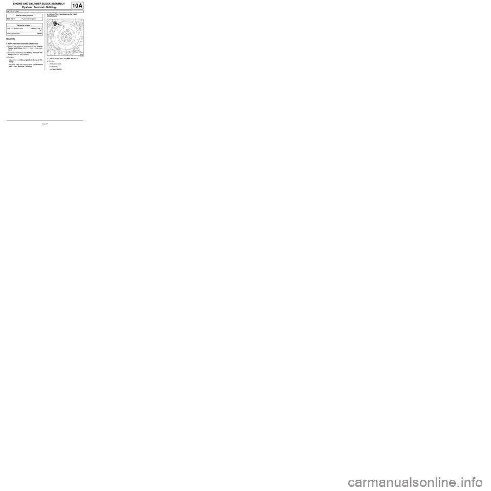
aLock the engine using tool (Mot. 582-01) (1) .
aRemove:
-the flywheel bolts,
-the flywheel,
-tool (Mot. 582-01). Special tooling required
Mot. 582-01Flywheel locking tool.
Tightening torquesm
D4F, D7F flywheel bolts18 Nm + 110˚ ±± ± ±
10˚
K9K flywheel bolts70 Nm
109158