brake RENAULT TWINGO RS 2009 2.G Engine And Peripherals Owner's Manual
[x] Cancel search | Manufacturer: RENAULT, Model Year: 2009, Model line: TWINGO RS, Model: RENAULT TWINGO RS 2009 2.GPages: 652
Page 364 of 652
13B-3
DIESEL INJECTION
Diesel injection: Precautions for the repair
K9K
13B
2 - Using the brake cleaner
Clear the access to the unions that need opening, fol-
lowing the work procedures specific to the vehicle (see
the relevant Workshop Repair Manual).
Protect sections which are sensitive to fuel leaks.
Spray the brake cleaner onto the unions to be opened.
Clean the unions carefully using fresh cleaning cloths.
Blast the components that have been cleaned with
compressed air (tools, workbench, and also parts,
unions and around the injection system). Check that no
bristles from the brush have come away and that the
area is clean.
Open the circuit at the unions and immediately fit the
relevant blanking plugs.WARNING
To prevent impurities from entering, once the fuel
circuit is opened, it must not be blasted with com-
pressed air. Use cleaning cloths only, if necessary.
IMPORTANT
Wear leaktight gloves (Nitrile type) for this opera-
tion.
IMPORTANT
Wear goggles with side protectors for this opera-
tion.
WARNING
To prevent impurities from entering, once the fuel
circuit is opened, it must not be blasted with com-
pressed air. Use cleaning cloths only, if necessary.
Page 434 of 652
14A-16
ANTIPOLLUTION
Exhaust gas recirculation assembly: Removal - Refitting
K9K
14A
aPull the intercooler air inlet pipe clip (5) on the turbo-
charger side.
aDisconnect the intercooler air inlet pipe (6) at the tur-
bocharger end.
aRemove the intercooler air inlet pipe nut (7) at the
turbocharger end.
aMove aside the intercooler air inlet pipe (6) at the tur-
bocharger end.
aDisconnect the vacuum pipe (8) from the turbo-
charging pressure regulator.
aUnclip:
-the turbocharging pressure regulator vacuum pipe
at (9) ,
-the brake servo vacuum pipe at (10) .
aDisconnect the brake servo vacuum pipe (11) .
aLoosen the clamp (12) for the air-air intercooler air
outlet pipe at the damper valve end.
aDisconnect the intercooler air outlet pipe (14) at the
damper valve end.
aRemove the nut (13) from the intercooler air outlet
pipe.
aMove the intercooler air outlet pipe (14) to one side. K9K, and 718
141222
141213
141217
Page 436 of 652
14A-18
ANTIPOLLUTION
Exhaust gas recirculation assembly: Removal - Refitting
K9K
14A
aRefit:
-new seals on the coolant circulation cover,
-the coolant circulation cover on the exhaust gas
cooler.
aTorque tighten the coolant circulation cover bolts
on the exhaust gas cooler (12 N.m).
aRemove the tool (Ms. 583) from the coolant inlet and
outlet hoses of the exhaust gas cooler.
III - FINAL OPERATION
aFit the intercooler air outlet pipe at the damper valve
end.
aConnect the intercooler air outlet pipe on the side of
the damper valve.
aTorque tighten the intercooler air outlet pipe clip
at the damper valve end (5.5 N.m).
aRefit the intercooler air outlet pipe nut on the lifting
eye.
aConnect the turbocharging pressure regulator vacu-
um pipe.
aClip:
-the turbocharging pressure regulator vacuum pipe,
-the vacuum pipe from the brake servo.
aConnect the brake servo vacuum pipe.
aFit the intercooler air inlet pipe at the turbocharger
end.
aRefit the intercooler air inlet pipe nut at the turbo-
charger end on the lifting eye.
aConnect the intercooler air inlet pipe at the turbo-
charger end.
aClip on the intercooler air inlet pipe clip at the turbo-
charger end.
aRefit the air outlet pipe onto the air filter unit.
aTighten the air filter unit air outlet pipe clip on the tur-
bocharger.
aConnect the oil vapour rebreathing pipe.
aRefit:
-the exhaust gas recirculation rigid pipe (see 14A,
Antipollution, Exhaust gas recirculation rigid
pipe: Removal - Refitting, page 14A-19) ,-the catalytic converter (see 19B, Exhaust, Cata-
lytic converter: Removal - Refitting, page 19B-
12) ,
-the lower engine tie-bar (see 19D, Engine mount-
ing, Lower engine tie-bar: Removal - Refitting,
page 19D-18) ,
-the EGR solenoid valve (see 14A, Antipollution,
Exhaust gas recirculation solenoid valve: Re-
moval - Refitting, page 14A-10) ,
-the air filter unit (see 12A, Fuel mixture, Air filter
unit: Removal - Refitting, page 12A-13) ,
-the scoop under the scuttle panel grille (see Scoop
under the scuttle panel grille: Removal - Refit-
ting) (56A, Exterior equipment).
-the scuttle panel grille (see Scuttle panel grille:
Removal - Refitting) (56A, Exterior equipment),
-the windscreen wiper arms (see Windscreen wip-
er arm: Removal - Refitting) (85A, Wiping -
Washing),
aConnect the battery (see ) (80A, Battery).
aFill and bleed the cooling system (see 19A, Cool-
ing, Cooling system: Draining - Refilling, page
19A-9) .
aRefit the engine cover. K9K, and 718
Page 553 of 652
19A-43
COOLING
Water chamber: Removal - Refitting
K9K
19A
aRemove the air filter unit (see 12A, Fuel mixture,
Air filter unit: Removal - Refitting, page 12A-13) .
aPull the intercooler air inlet pipe clip (1) at the turbo-
charger end.
aDisconnect the intercooler air inlet pipe (2) at the tur-
bocharger end.
aRemove the nut (3) from the intercooler air inlet pipe
at the turbocharger end.
aMove aside the intercooler air inlet pipe (2) at the tur-
bocharger end.
aRemove the nut (4) from the intercooler air outlet
pipe at the damper valve end.
aDisconnect the turbocharging pressure regulator
vacuum pipe (5) .
aUnclip:
-the turbocharging pressure regulator vacuum pipe
at (6) ,
-the brake servo vacuum pipe at (7) .
aDisconnect the brake servo vacuum pipe (8) .
aLoosen the clamp (9) for the air-air intercooler air
outlet pipe at the damper valve end.
aDisconnect the intercooler air outlet pipe (10) at the
damper valve end.
aMove aside the intercooler air outlet pipe (10) at the
damper valve end. K9K, and 718
141222
141213
141217
Page 555 of 652
19A-45
COOLING
Water chamber: Removal - Refitting
K9K
19A
II - REFITTING OPERATION FOR PART
CONCERNED
aRefit the thermostat to the water chamber.
aRefit:
-a new water chamber seal,
-the water chamber.
aTorque tighten the water chamber bolts (10 N.m).
III - FINAL OPERATION
aConnect the cooling hoses on the water chamber.
aPosition the cooling hose clips on the water chamber
using the tool (Mot. 1448).
aClip on the cooling hose of the coolant-oil heat ex-
changer.
aConnect the intercooler air outlet pipe on the side of
the damper valve.
aTorque tighten the intercooler air outlet pipe clip
at the damper valve end (5.5 N.m).
aConnect the brake servo vacuum pipe.
aClip:
-the turbocharging pressure regulator vacuum pipe,
-the vacuum pipe from the brake servo.
aConnect the turbocharging pressure regulator vacu-
um pipe.
aRefit the nuts of the air hoses on the lifting eye.
aConnect the intercooler air inlet pipe at the turbo-
charger end.
aClip on the intercooler air inlet pipe clip at the turbo-
charger end.
aFill the cooling system (see 19A, Cooling, Cooling
system: Draining - Refilling, page 19A-9) .
aRefit the engine cover. K9K, and 718
Page 606 of 652
19B-24
EXHAUST
Expansion chamber: Removal - Refitting
D4F, and 780 or 782
19B
aCut the exhaust pipe (see 19B, Exhaust, Exhaust:
Precautions for the repair, page 19B-8) in the area
designated to be cut (see ) .
aRemove:
-the expansion chamber rubber mounting bush bolt
from the body,
-the expansion chamber,
-the rubber mounting bush bolt from the expansion
chamber,
-the expansion chamber rubber mounting bush.
REFITTING THE EXPANSION CHAMBER
I - REMOVAL OPERATION FOR PART
CONCERNED
aRefit:
-the expansion chamber rubber mounting bush,
-the expansion chamber rubber mounting bush bolt.
aFit the expansion chamber.
aAttach the expansion chamber to the vehicle using
the expansion chamber rubber mounting bush bolt.
aFit a new After-Sales sleeve (see 19B, Exhaust, Ex-
haust: Precautions for the repair, page 19B-8) .
aTighten the exhaust trunking.
aTighten the expansion chamber rubber mounting
bush bolt on the body.
aRefit a new clip between the front section of the ex-
pansion chamber and the expansion chamber.
aTighten the clip between the front section of the ex-
pansion chamber and the expansion chamber.II - FINAL OPERATION
aCheck the following and deal with if necessary:
-that there is no contact with the underbody,
-the presence and correct positioning of all the ex-
haust pipe heat shields.
aStart the vehicle.
aCheck that there are no leaks and deal with them if
necessary.
Note:
If the rubber mounting bushes are damaged,
mark the position of the support on the body,
then replace the « support - rubber mounting
bush » assembly.
Note:
If replacing the rubber mounting bush, spray the
inside of the rubber mounting bush with BRAKE
CLEANER (see Vehicle: Parts and consum-
ables for the repair) (MR 411, 04B, Consum-
ables - Products) to facilitate fitting.
Page 611 of 652
19B-29
EXHAUST
Intermediate pipe: Removal - Refitting
K9K
19B
REFITTING THE INTERMEDIATE PIPE
REFITTING OPERATION FOR PART CONCERNED
aRefit:
-the rubber mounting bush of the intermediate pipe,
-the rubber mounting bush bolt on the intermediate
pipe.
aFit the intermediate pipe.
aAttach the intermediate pipe to the vehicle using the
intermediate pipe rubber mounting bush bolt.
aFit a new After-Sales sleeve and follow the instruc-
tions (see 19B, Exhaust, Exhaust: Precautions
for the repair, page 19B-8) .
aRefit a new clip between the front section of the in-
termediate pipe and the intermediate pipe.
aCheck the following and deal with if necessary:
-that there is no contact with the underbody,
-the presence and correct positioning of all the ex-
haust pipe heat shields.
aStart the engine.
aCheck that there are no leaks and deal with them if
necessary.Note:
If replacing the rubber mounting bush, spray the
inside of the rubber mounting bush with BRAKE
CLEANER ( (see Vehicle: Parts and consum-
ables for the repair) ) in the form of an aerosol
spray to facilitate fitting.
Page 612 of 652
19B-30
EXHAUST
Intermediate pipe: Removal - Refitting
D4F, and 772 – D7F
19B
REMOVAL
I - REMOVAL PREPARATION OPERATION
aPosition the vehicle on a two-post lift (see Vehicle:
Towing and lifting) (02A, Lifting equipment).
II - OPERATION FOR REMOVAL OF PART
CONCERNED
aRemove the clip between the catalytic converter and
the intermediate pipe.
aRemove the intermediate pipe
aCut the exhaust pipe (see 19B, Exhaust, Exhaust:
Precautions for the repair, page 19B-8) in the des-
ignated area to be cut (see ) .
aRemove:
-the intermediate pipe rubber mounting bush bolt on
the body,
-the connector pipe,
-the rubber mounting bush bolt on the intermediate
pipe,
-the intermediate pipe rubber mounting bush.
REFITTING
REFITTING OPERATION FOR PART CONCERNED
aRefit:
-the rubber mounting bush of the intermediate pipe,
-the rubber mounting bush bolt on the intermediate
pipe.
aFit the intermediate pipe.
aAttach the intermediate pipe to the vehicle using the
intermediate pipe rubber mounting bush bolt.
aFit a new After-Sales sleeve and follow the instruc-
tions (see 19B, Exhaust, Exhaust: Precautions
for the repair, page 19B-8) .
aRefit a new clip between the front section of the in-
termediate pipe and the intermediate pipe.aCheck the following and deal with if necessary:
-that there is no contact with the underbody,
-the presence and correct positioning of all the ex-
haust pipe heat shields.
aStart the vehicle.
aCheck that there are no leaks and deal with them if
necessary.
Note:
If replacing the rubber mounting bush, spray the
inside of the rubber mounting bush with aerosol
spray BRAKE CLEANER (see Vehicle: Parts
and consumables for the repair) (04B, Con-
sumables - Products) to facilitate fitting.
Page 613 of 652
19B-31
EXHAUST
Silencer: Removal - Refitting
D4F or D7F or K9K
19B
REMOVAL
I - REMOVAL PREPARATION OPERATION
aPosition the vehicle on a two-post lift (see Vehicle:
Towing and lifting) (MR 411, 02A, Lifting equip-
ment).
II - REMOVAL OPERATION FOR PART
CONCERNED
aRemove the expansion chamber rubber mounting
bush bolt from the body.
aCut the exhaust pipe (see 19B, Exhaust, Exhaust:
Precautions for the repair, page 19B-8) in the des-
ignated area to be cut (see ) .
aDetach the rubber mounting bush rear silencer.
aRemove the rear silencer.
REFITTING
I - REFITTING OPERATION FOR PART
CONCERNED
a
aFit:
-the rear silencer,
-the new After-Sales sleeve (see 19B, Exhaust,
Exhaust: Precautions for the repair, page 19B-
8) .
aTighten the exhaust trunking.
aRefit the expansion chamber rubber mounting bush
bolt on the body.II - FINAL OPERATION
aCheck (and correct if necessary):
-that there is no contact with the underbody,
-the presence and correct positioning of all the ex-
haust pipe heat shields.
aStart the vehicle.
aCheck that there are no leaks and deal with them if
necessary.
D4F, and 780
Note:
If replacing the rubber mounting bush, spray the
inside of the rubber mounting bush with brake
cleaner (see Vehicle: Parts and consumables
for the repair) (MR 411, 04B, Consumables -
products) to facilitate fitting.
D4F, and 780
Page 619 of 652
19C-5
TANK
Fuel tank: Removal - Refitting
D4F or D7F or K4M or K9K
19C
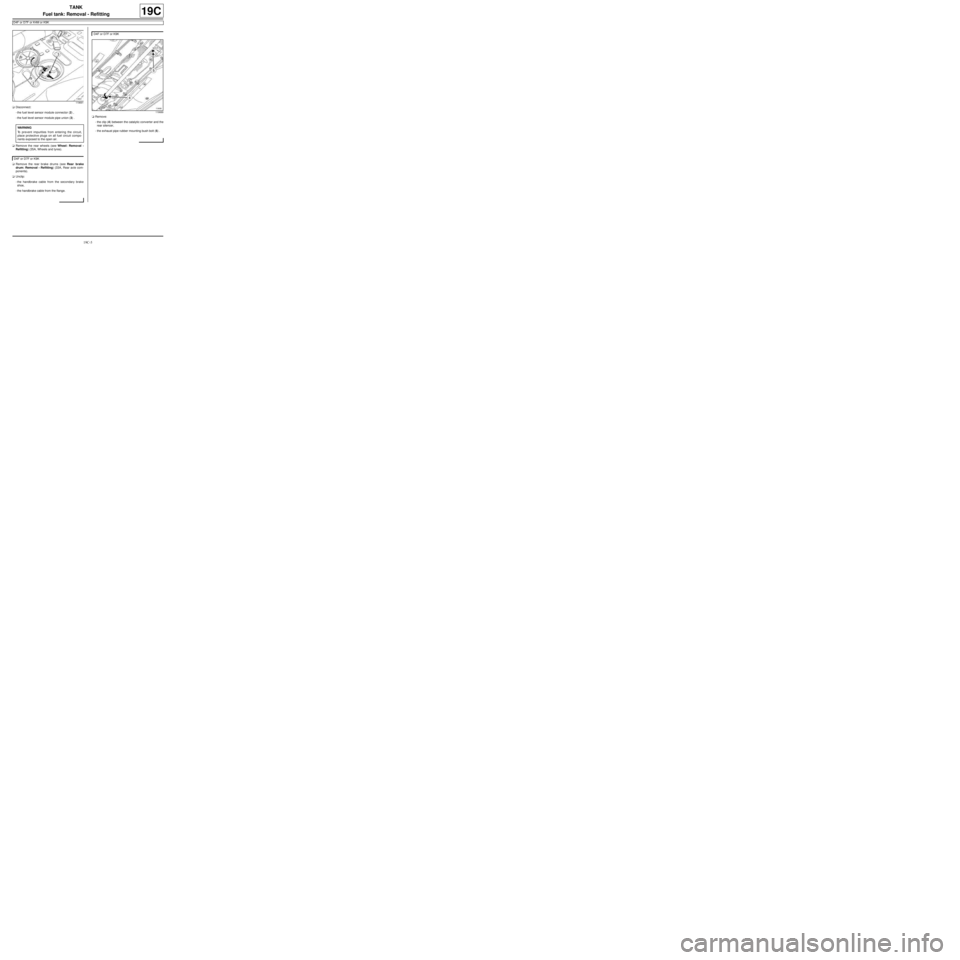
aDisconnect:
-the fuel level sensor module connector (2) ,
-the fuel level sensor module pipe union (3) .
aRemove the rear wheels (see Wheel: Removal -
Refitting) (35A, Wheels and tyres).
aRemove the rear brake drums (see Rear brake
drum: Removal - Refitting) (33A, Rear axle com-
ponents).
aUnclip:
-the handbrake cable from the secondary brake
shoe,
-the handbrake cable from the flange.aRemove:
-the clip (4) between the catalytic converter and the
rear silencer,
-the exhaust pipe rubber mounting bush bolt (5) .
119691
WARNING
To prevent impurities from entering the circuit,
place protective plugs on all fuel circuit compo-
nents exposed to the open air.
D4F or D7F or K9K
D4F or D7F or K9K
119689