RENAULT TWINGO RS 2009 2.G Panelwork Workshop Manual
Manufacturer: RENAULT, Model Year: 2009, Model line: TWINGO RS, Model: RENAULT TWINGO RS 2009 2.GPages: 209
Page 1 of 209
© Renault s.a.s 2007 "The repair procedures given by the manufacturer in this document are based on the
technical specifications current when it was prepared.
The procedures may be modified as a result of changes introduced by the manufacturer in
the production of the various component units and accessories from which the vehicles are
constructed".All rights reserved by Renault.
Copying or translating, in part or in full, of this document or use of the service part reference
numbering system is forbidden without the prior written authority of Renault.
JUNE 2009 EDITION ANGLAISE
X44
4Panelwork
40AGENERAL INFORMATION
41AFRONT LOWER STRUCTURE
41BCENTRE LOWER STRUCTURE
41CSIDE LOWER STRUCTURE
41DREAR LOWER STRUCTURE
42AFRONT UPPER STRUCTURE
43ASIDE UPPER STRUCTURE
44AREAR UPPER STRUCTURE
45ATOP OF BODY
47ASIDE OPENING ELEMENTS
48ANON-SIDE OPENING ELEMENTS
Page 2 of 209
TWINGO - Section 4
Contents
Pages
TWINGO - Section 4 ContentsPages
40A GENERAL INFORMATION
Specialised bodywork tools:
Use 40A-1
Vehicle on repair bench:
Description 40A-5
Subframe: Specifications 40A-7
Hollow section inserts: List
and location of components 40A-9
Hollow section inserts:
Precautions for the repair 40A-11
Earths on body: List and
location of components 40A-12
Vehicle structure, front
section: Description 40A-15
Vehicle structure, side
section: Description 40A-17
Vehicle structure, centre
section: Description 40A-19
Vehicle structure, rear
section: Description 40A-21
Vehicle structure, removable
section: Description 40A-23
Structural components to be
positioned on the repair
bench: Description 40A-25
Structural bodywork
documentation: Description 40A-2941A FRONT LOWER STRUCTURE
Front end lower cross
member: General description 41A-1
Front end lower cross
member: Description 41A-2
Radiator mounting cross
member: General description 41A-4
Radiator mounting cross
member: Removal - Refitting 41A-5
Front side member: General
descr iption 41A-6
Front side member, front
section: Description 41A-8
Front side member closure
panel, front section: General
descr iption 41A-11
Front side member closure
panel, front section:
Description 41A-13
Front side member, rear
section: Description 41A-15
Front subframe front
mounting: General
descr iption 41A-17
Front subframe front
mounting: Description 41A-18
Engine stand: General
descr iption 41A-20
Engine stand: Description 41A-21
Page 3 of 209
Contents
Front half unit: General
descr iption 41A-23
Front half unit: Description 41A-24
41B CENTRE LOWER STRUCTURE
Centre floor, side section:
General description 41B-1
Centre floor, side section:
Description 41B-3
Centre floor front side cross
member: General description 41B-5
Centre floor front side cross
member: Description 41B-7
Front cross member under
front seat: General
descr iption 41B-8
Front cross member under
front seat: Description 41B-9
Rear cross member under
front seat: General
descr iption 41B-10
Rear cross member under
front seat: Description 41B-11
41C SIDE LOWER STRUCTURE
Sill panel: General
descr iption 41C-1
Sill panel: Description 41C-5
Sill panel closure panel:
General description 41C-8
Sill panel closure panel:
Description 41C-10
Sill panel reinforcement:
General description 41C-12 41A FRONT LOWER STRUCTURESill panel reinforcement:
Description 41C-13
Sill panel stiffener:
Description 41C-15
41D REAR LOWER STRUCTURE
Rear fl oor: Description 41D-1
Raised rear floor, front
section: Removal - Refitting 41D-4
Rear side member assembly:
Description 41D-5
Rear side member : General
descr iption 41D-7
Rear side member :
Description 41D-8
Rear fl oor front cross
member: General description 41D-10
Rear fl oor front cross
member: Description 41D-12
Rear fl oor centre cross
member: General description 41D-13
Rear fl oor centre cross
member: Description 41D-14
Rear towing eye: Description 41D-16
Rear impact lower cross
member: Removal - Refitting 41D-18
42A FRONT UPPER STRUCTURE
Front wing: General
descr iption 42A-1
Front wing: Removal -
Refitting 42A-3
Front wing: Adjustment 42A-4
Front wing upper mounting
support: General description 42A-6 41C SIDE LOWER STRUCTURE
Page 4 of 209
Contents
Front wing upper mounting
support: Removal - Refi tting 42A-7
Front end panel: General
descr iption 42A-8
Front end panel: Removal -
Refitting 42A-9
Headlight carrier panel:
Removal - Refitting 42A-11
Front upper cross member:
General description 42A-12
Front upper cross member:
Removal - Refitting 42A-13
Scuttle side panel: General
descr iption 42A-14
Scuttle side panel:
Description 42A-16
Upper reinforcement of
scuttle side panel: General
descr iption 42A-18
Upper reinforcement of
scuttle side panel:
Description 42A-19
Front wheel arch: General
descr iption 42A-21
Front wheel arch: Description 42A-22
Front wheel arch, front
section: General description 42A-25
Dashboard cross member:
Removal - Refitting 42A-26
Windscreen aperture lower
cross member closure panel:
Description 42A-28
43A SIDE UPPER STRUCTURE
A-pillar : General description 43A-1
A-pillar : Description 43A-2
A-pillar reinforcement:
General description 43A-5 42A FRONT UPPER STRUCTUREA-pillar reinforcement:
Description 43A-6
Windscreen pillar lining:
General description 43A-8
B-pillar reinforcement:
General description 43A-9
B-pillar reinforcement:
Description 43A-10
Body side: General
descr iption 43A-12
Body side: Description 43A-13
Upper body: General
descr iption 43A-15
Upper body: Description 43A-17
44A REAR UPPER STRUCTURE
Rear wing panel: General
descr iption 44A-1
Rear wing panel: Description 44A-2
Rear lights mounting:
General description 44A-5
Rear lights mounting:
Description 44A-6
Outer rear wheel arch:
General description 44A-8
Outer rear wheel arch:
Description 44A-10
Inner rear wheel arch:
General description 44A-13
Inner rear wheel arch:
Description 44A-14
Quar ter panel lining: General
descr iption 44A-16
Quar ter panel lining:
Description 44A-17
Rear end panel assembly:
Description 44A-22 43A SIDE UPPER STRUCTURE
Page 5 of 209
Contents
Rear end panel: General
descr iption 44A-24
Rear end panel: Description 44A-25
45A TOP OF BODY
Roof: General description 45A-1
Roof: Description 45A-2
Roof front section:
Description 45A-6
Roof rear section:
Description 45A-7
Roof front cross member:
General description 45A-8
Roof centre cross member:
General description 45A-9
Roof rear cross member:
General description 45A-10
47A SIDE OPENING ELEMENTS
Front side door: Removal -
Refitting 47A-1
Front side door: Stripping -
rebuilding 47A-3
Front side door: Adjustment 47A-5
Fuel filler flap co ver:
Removal - Refitting 47A-8
48A NON-SIDE OPENING ELEMENTS
Bonnet: Removal - Refitting 48A-1
Bonnet: Stripping -
Rebuilding 48A-3
Bonnet: Adjustment 48A-4
Tailgate: Removal - Refitting 48A-6 44A REAR UPPER STRUCTURETailgate: Stripping -
Rebuilding 48A-8
Tailgate: Adjustment 48A-10 48A NON-SIDE OPENING ELEMENTS
Page 6 of 209
40A-1
GENERAL INFORMATION
Specialised bodywork tools: Use
40A
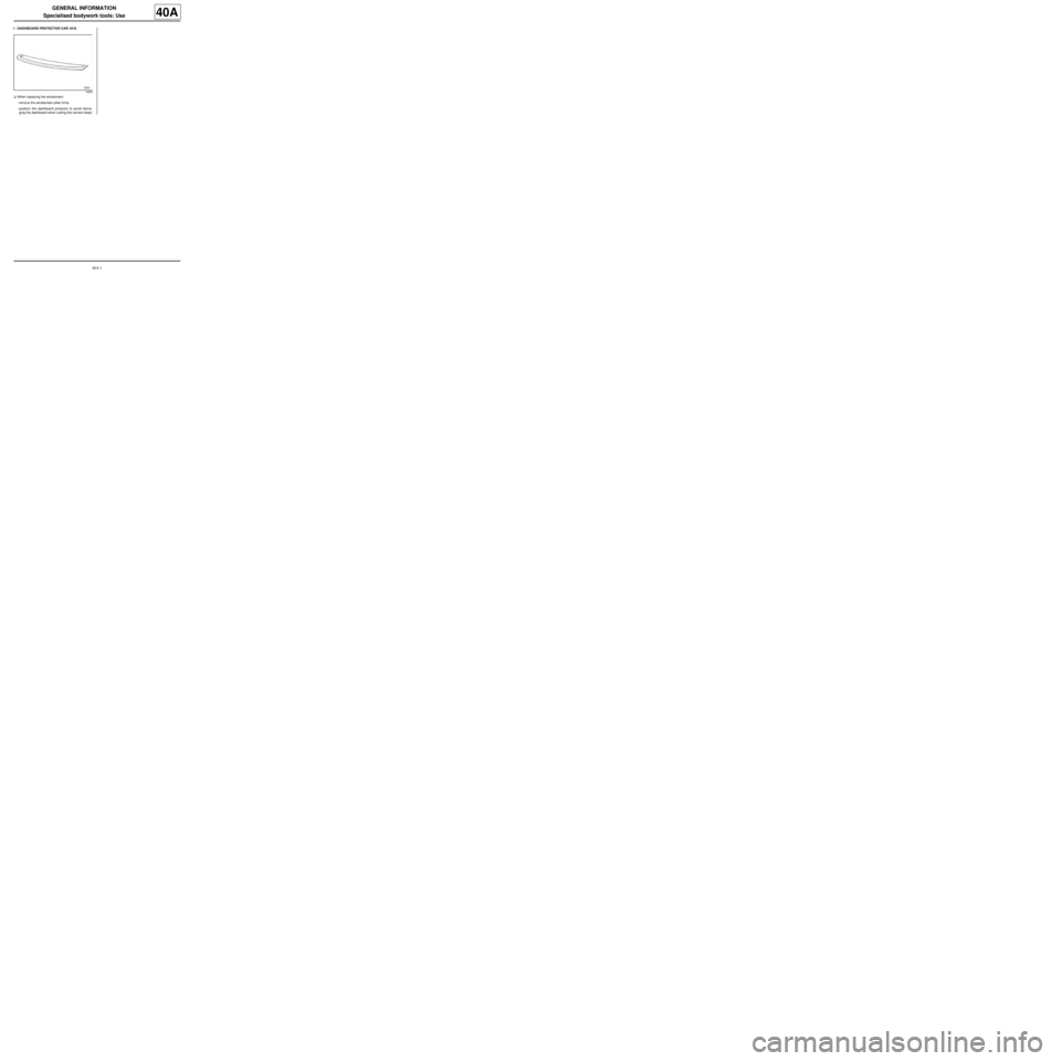
I - DASHBOARD PROTECTOR CAR.1818
aWhen replacing the windscreen:
-remove the windscreen pillar trims,
-position the dashboard protector to avoid dama-
ging the dashboard when cutting the cement bead.
18263
Page 7 of 209
40A-2
GENERAL INFORMATION
Specialised bodywork tools: Use
40A
II - CRIMPED NUT FITTING TOOL CAR.1504
Page 8 of 209
40A-3
GENERAL INFORMATION
Specialised bodywork tools: Use
40A
111554
Page 9 of 209
40A-4
GENERAL INFORMATION
Specialised bodywork tools: Use
40A
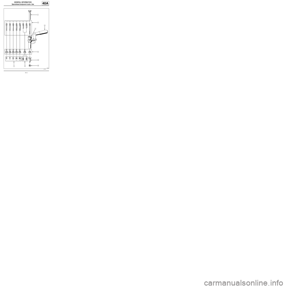
aComponents of tool Car. 1504 :
- (1) : Mandrel mounting,
- (2) : Mandrels,
- (3) : Tightening bolt,
- (4) : Body,
- (5) : Anvils,
- (6) : Special nut,
- (7) : Nut,
- (8) : Studs,
- (9) : Thrust nut.
1 - Tool preparation
aSelect the mandrel, anvil and insert assembly adap-
ted to the crimping operation to be carried out.
aScrew the mandrel (2) into the mandrel mounting (1)
(left-hand thread).
aTighten the bolt (3) onto the body (4) until the stop
(left-hand thread).
aScrew the anvil (5) into the body (4) (left-hand
thread)
aFit the assembly (1) and (2) into the body of the tool.
aScrew the insert (left-hand thread) onto the pull rod.2 - Using the tool
aTurn the tightening bolt (3) using a 24 mm wrench
while holding the tool handle.
Note:
To fi t the special nut (6) , insert the mandrel (2)
through the nut to be crimped and tighten it onto
the thrust nut (9) .
WARNING
Each time a panel is stripped in the workshop
(e.g. when drilling), degrease and wipe the area
and then use a fine paintbrush to apply the fol-
lowing:
-a pre-treatment primer,
-a two-part pr imer,
-paint in the vehicle body colour.
WARNING
The operator should be able to feel when the
crimping is complete (more force required for
tightening).
The insert has been crimped correctly when
there is no rotational play. Carry out this check
before unscrewing the « pull rod - mandrel »
assembly.
Page 10 of 209
40A-5
GENERAL INFORMATION
Vehicle on repair bench: Description
C44
40A
I - MAIN FRONT TRIM-SETTING REFERENCE
POINTS
1 - Front sub-frame in place
the jig covers the subframe bolt (A) .
Use this situation for a rear impact or a light frontal im-
pact without removing the mechanical components.
2 - Front sub-frame removed
The jig rests against the rear section of the side mem-
ber and is centred in the sub-frame rear mounting hole
(A) .Use this situation for a frontal impact with removal of
the mechanical components.
II - SECONDARY FRONT TRIM-SETTING
REFERENCE POINT
The jig covers the front subframe front mounting bolt
(C) .
Use this situation to confirm the trim-setting following a
rear impact, (e.g.: to replace a rear side member as-
sembly).
It is used to confirm the vehicle level in case of doubt
about the deformation of a main rear reference point.
120611
121747
Note:
If it is suspected that one of these points may be
deformed, use two additional points located in an
area not affected by the impact in order to confirm
trim-setting.
120610