sensor RENAULT TWINGO RS 2009 2.G Engine And Peripherals Owner's Manual
[x] Cancel search | Manufacturer: RENAULT, Model Year: 2009, Model line: TWINGO RS, Model: RENAULT TWINGO RS 2009 2.GPages: 652
Page 89 of 652
10A-83
ENGINE AND CYLINDER BLOCK ASSEMBLY
Engine - gearbox assembly: Removal - Refitting
D4F or D7F
10A
aTorque tighten:
-the front subframe bolts (62 N.m),
-the rear subframe bolts (105 N.m),
-the subframe rear tie rod inner bolts (21 N.m),
-the subframe rear tie rod outer bolts (90 N.m),
-the engine tie-bar bolts on the gearbox (105
N.m),
-the engine tie-bar bolt on the subframe (105
N.m).
aRefit the control cables onto the gearbox.
aRemove the blanking plugs from the openings.
aClip the clutch pipe onto the gearbox.
aConnect the clutch slave cylinder.
aRemove the hose clamp (Ms. 583).
aBleed the clutch circuit (see Clutch circuit: Bleed) .
aRefit the gear control linkage.
aAttach the gear control linkage to:
-the gear lever,
-the control lever on the gearbox.
aRefit:
-the heat shield,
-the heat shield bolts.
aRefit the clutch control cable on the manual gearbox.
aRefit the catalytic converter (see 19B, Exhaust,
Catalytic converter: Removal - Refitting, page
19B-12) .aRefit the exhaust downpipe.
aFit the clip.
aTighten the intermediate pipe clip.
aRefit the exhaust downpipe bolts.
aTorque tighten the exhaust downpipe bolts (9
N.m).
aRefit:
-the shock absorber base lower bolts,
-the ABS sensors,
-the ABS sensor bolts (if fitted to the vehicle),
-the brake callipers,
-the calliper mounting bolts,
-the brake pads,
-the lower guide pin bolts,
-track rod ends,
-the track rod end nuts,
-the tie rod upper bolts.
aTorque tighten:
-the shock absorber base lower bolts (105 N.m ),
-the calliper mounting bolts (105 N.m),
-the lower guide pin bolts (34 N.m),
-the track rod end nuts (37 N.m),
-the tie rod upper bolts (21 N.m),
-the tie rod lower bolts (62 N.m).
aClip the electrical wiring on to the cross member.
aFit the steering box universal joint.
aRefit the universal joint bolt.
aTorque tighten the universal joint (24 N.m).
aRemove the flywheel immobiliser.
aClip the fuel pipe on to the upper timing cover.
aConnect the fuel supply pipe union.
aConnect the air conditioning pressostat connector. JH3
JB1 or JH1
D4F, and 772 – D7F
D4F, and 780 or 782
AIR CONDITIONING
Page 107 of 652
10A-101
ENGINE AND CYLINDER BLOCK ASSEMBLY
Engine - gearbox assembly: Removal - Refitting
K4M
10A
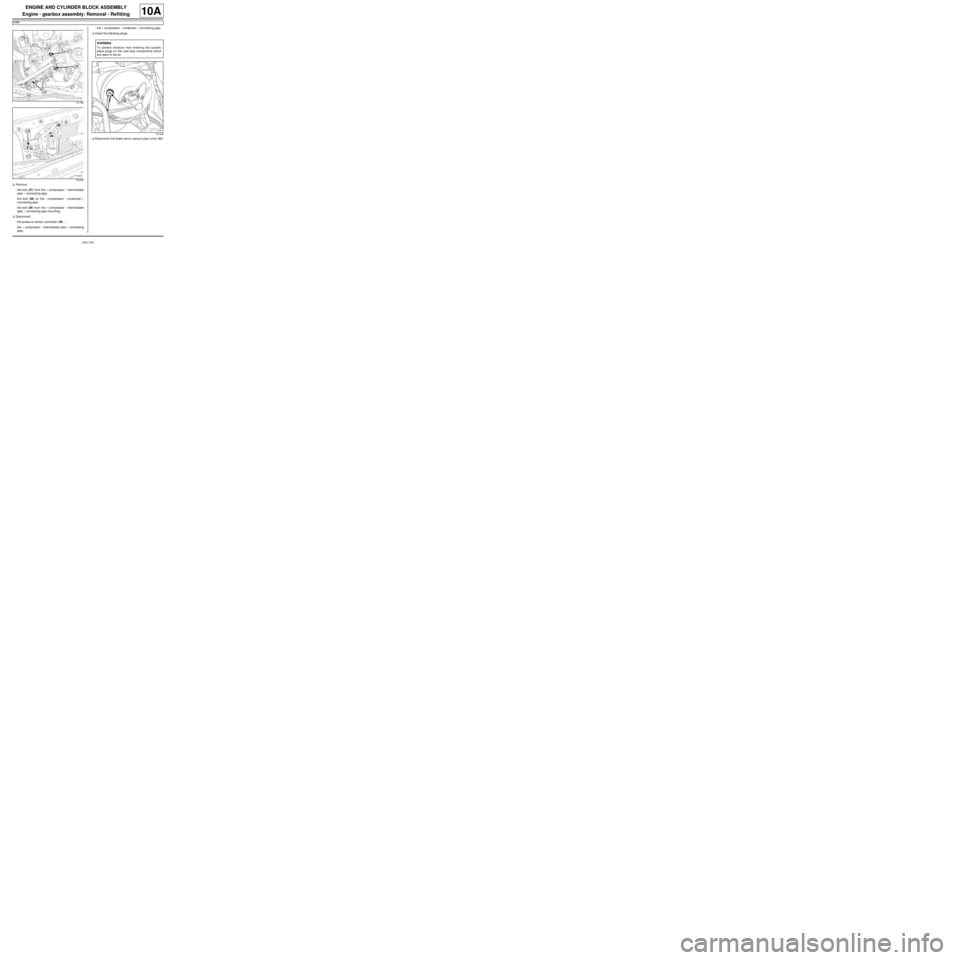
aRemove:
-the bolt (27) from the « compressor - intermediate
pipe » connecting pipe,
-the bolt (28) on the « compressor - condenser »
connecting pipe,
-the bolt (29) from the « compressor - intermediate
pipe » connecting pipe mounting.
aDisconnect:
-the pressure sensor connector (30) ,
-the « compressor - intermediate pipe » connecting
pipe,-the « compressor - condenser » connecting pipe.
aInsert the blanking plugs.
aDisconnect the brake servo vacuum pipe union (31)
.
131782
132335
WARNING
To prevent moisture from entering the system,
place plugs on the cold loop components which
are open to the air.
121348
Page 109 of 652
10A-103
ENGINE AND CYLINDER BLOCK ASSEMBLY
Engine - gearbox assembly: Removal - Refitting
K4M
10A
-the rubber pad mounting from the suspended en-
gine mounting on the gearbox.
aRemove the right-hand suspended engine mounting
(see 19D, Engine mounting, Right-hand sus-
pended engine mounting: Removal - Refitting,
page 19D-13) .
aLift the vehicle to remove the "engine and gearbox"
assembly.
REFITTING
I - REFITTING PREPARATION OPERATION
aFor standard engine replacement (see Standard re-
placement) (Technical Note 6023A, 10A, Engine
and peripherals).
II - REFITTING OPERATION
aPosition the "engine and gearbox" assembly in the
body.
aRefit the right-hand suspended engine mounting
(see 19D, Engine mounting, Right-hand sus-
pended engine mounting: Removal - Refitting,
page 19D-13) .
aRefit the rubber pad mounting from the suspended
engine mounting on the gearbox.
aTorque tighten the rubber pad mounting bolts for
the suspended engine mounting on the gearbox
(21 N.m).
aRefit the suspended engine mounting rubber pad.
aTorque tighten:
-the bolts of the suspended mounting rubber
pad (62 N.m),
-the suspended engine mounting shaft nut (62
N.m).
III - FINAL OPERATION
aRemove the.
aRemove the blanking plugs.
aConnect:
-the union of the brake servo vacuum pipe,
-the « compressor - condenser » connecting pipe,-the « compressor - intermediate pipe » connecting
pipe,
-the pressure sensor connector,
aConnect the hose on the coolant pump inlet pipe.
aFit the hose clip on the coolant pump inlet pipe using
the (Mot. 1448).
aRefit the earth nuts.
aClip:
-the relay plates on the engine compartment con-
nection unit,
-the fuse holders.
aConnect the fuses.
aRefit the engine compartment connection unit on the
body.
aConnect the connector to the engine compartment
connection unit.
aRefit the engine compartment connection unit cover.
aClip:
-the wiring on the engine cooling fan assembly,
-the cooling radiator top and bottom hoses on the
engine cooling fan assembly.
aConnect:
-the engine cooling fan assembly resistor connec-
tor,
-the engine cooling fan assembly connector.
aRemove the blanking plug from the fuel supply pipe
opening and the injector rail fuel opening.
aReconnect the fuel supply pipe.
aClip the fuel supply pipe in place.
aConnect:
-the fuel vapour absorber bleed solenoid valve con-
nector,
-the fuel vapour absorber bleed solenoid valve pipe.
aFit the gearbox control cables.
aClip the manual gearbox control cables onto:
-the gear selectors,
-the cable sleeve stops.
aRemove the blanking plug from the hydraulic clutch
control pipe opening and the opening of the clutch
thrust bearing.
aConnect the hydraulic clutch control pipe.
aClip the hydraulic clutch control pipe on the gearbox. Note:
Check no component obstructs the movement of
the body around the engine - gearbox assembly.
Page 140 of 652
11A-23
TOP AND FRONT OF ENGINE
Crankshaft accessories pulley: Removal - Refitting
C44, and K9K
11A
PARTS AND CONSUMABLES FOR THE
REPAIR WORK
aParts always to be replaced:
-accessories belt,
-accessories belt auto tensioner,
-accessories belt auto tensioner bolt.
REMOVAL
I - REMOVAL PREPARATION OPERATION
aPosition the vehicle on a two-post lift ( (see Vehicle:
Towing and lifting) ).aDisconnect the battery ( (see Battery: Removal -
Refitting) ).
aRemove:
-the front right-hand wheel ( (see Wheel: Removal
- Refitting) ),
-the front right-hand wheel arch liner ( (see Front
wheel arch liner: Removal - Refitting) ),
-the accessories belt (see 11A, Top and front of
engine, Accessories belt: Removal - Refitting,
page 11A-3) ,
-the accessories belt auto tensioner.
II - OPERATION FOR REMOVAL OF PART
CONCERNED
aRemove:
-the crankshaft position sensor (see 13B, Diesel in-
jection, Crankshaft position sensor: Removal -Refitting, page 13B-15) , Tightening torquesm
crankshaft accessories
pulley bolt80 Nm
19656
Page 141 of 652
11A-24
TOP AND FRONT OF ENGINE
Crankshaft accessories pulley: Removal - Refitting
C44, and K9K
11A
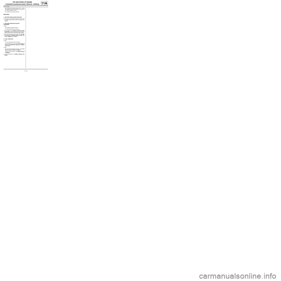
-the crankshaft accessories pulley bolt (1) , locking
the flywheel using a flat screwdriver at the point of
the crankshaft position sensor,
-the crankshaft accessories pulley (2) .
REFITTING
I - REFITTING PREPARATIONS OPERATION
aIf reusing the crankshaft accessories pulley, clean
the pulley V-grooves with a brush to eliminate any
deposits.
II - REFITTING OPERATION FOR PART
CONCERNED
aRefit:
-the crankshaft accessories pulley,
-the crankshaft accessories pulley bolt.
aTorque tighten the crankshaft accessories pulley
bolt (80 Nm), locking the flywheel using a flat screw-
driver at the point of the crankshaft position sensor.
aRefit the crankshaft position sensor (see 13B, Die-
sel injection, Crankshaft position sensor: Re-
moval - Refitting, page 13B-15) .
III - FINAL OPERATION.
aRefit:
-the new accessories belt auto tensioner,
-the accessories belt (see 11A, Top and front of
engine, Accessories belt: Removal - Refitting,
page 11A-3) .
aRefit:
-the front right-hand wheel arch liner ( (see Front
wheel arch liner: Removal - Refitting) ),
-the front right-hand wheel ( (see Wheel: Removal
- Refitting) ).
aConnect the battery ( (see Battery: Removal - Re-
fitting) ).
Page 149 of 652
11A-32
TOP AND FRONT OF ENGINE
Timing belt: Removal - Refitting
D4F
11A
aMove the flexible heat shield away from the oil pres-
sure sensor connector.
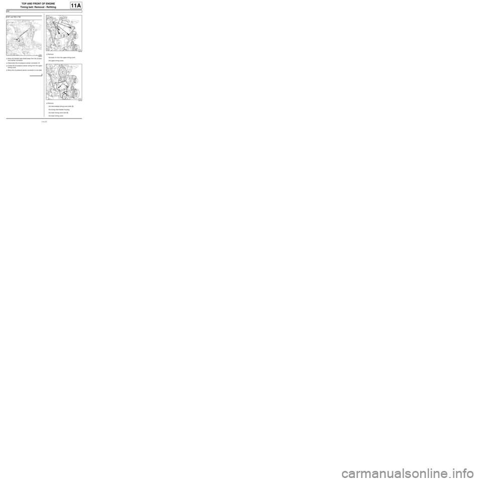
aDisconnect the oil pressure sensor connector (1) .
aUnclip the oil pressure sensor wiring from the upper
timing cover.
aMove the oil pressure sensor connector to one side.aRemove:
-the bolts (1) from the upper timing cover,
-the upper timing cover.
aRemove:
-the intermediate timing cover bolts (2) ,
-the timing intermediate housing,
-the lower timing cover bolt (3) ,
-the lower timing cover. D4F, and 780 or 782
122664
109740
109739
Page 154 of 652
11A-37
TOP AND FRONT OF ENGINE
Timing belt: Removal - Refitting
D4F
11A
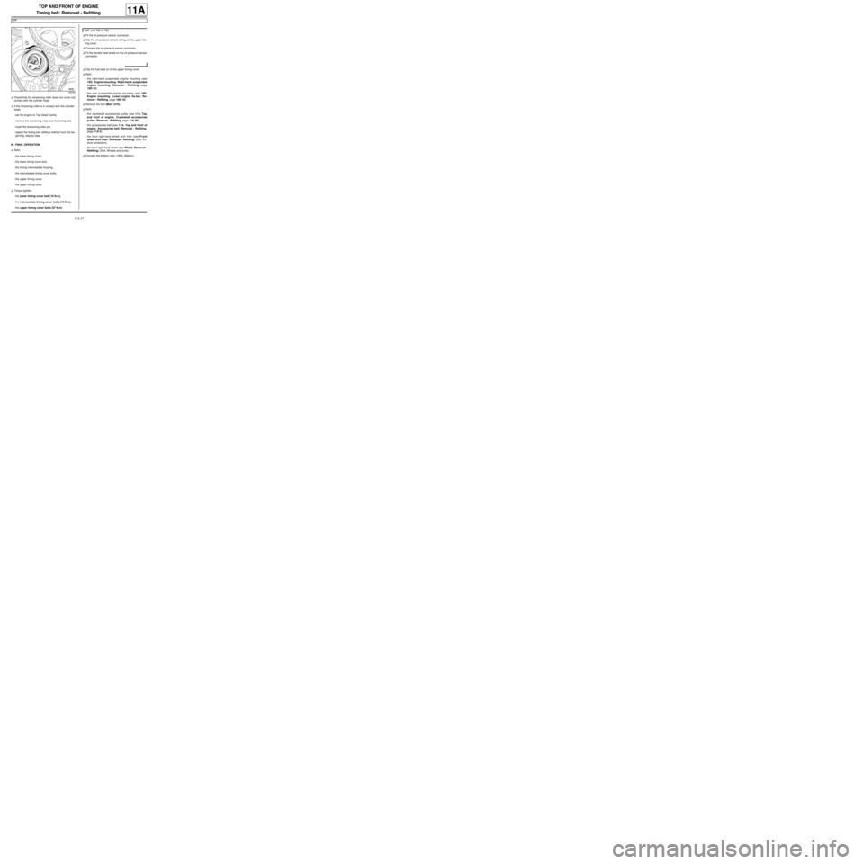
aCheck that the tensioning roller does not come into
contact with the cylinder head.
aIf the tensioning roller is in contact with the cylinder
head:
-set the engine to Top Dead Centre,
-remove the tensioning roller and the timing belt,
-insert the tensioning roller pin,
-repeat the timing belt refitting method from the be-
ginning, step by step.
III - FINAL OPERATION
aRefit:
-the lower timing cover,
-the lower timing cover bolt,
-the timing intermediate housing,
-the intermediate timing cover bolts,
-the upper timing cover,
-the upper timing cover.
aTorque tighten:
-the lower timing cover bolt (10 N.m),
-the intermediate timing cover bolts (10 N.m),
-the upper timing cover bolts (37 N.m)aFit the oil pressure sensor connector.
aClip the oil pressure sensor wiring on the upper tim-
ing cover.
aConnect the oil pressure sensor connector.
aFit the flexible heat shield on the oil pressure sensor
connector.
aClip the fuel pipe on to the upper timing cover.
aRefit:
-the right-hand suspended engine mounting (see
19D, Engine mounting, Right-hand suspended
engine mounting: Removal - Refitting, page
19D-13) ,
-the rear suspended engine mounting (see 19D,
Engine mounting, Lower engine tie-bar: Re-
moval - Refitting, page 19D-18) .
aRemove the tool (Mot. 1379).
aRefit:
-the crankshaft accessories pulley (see 11A, Top
and front of engine, Crankshaft accessories
pulley: Removal - Refitting, page 11A-20) ,
-the accessories belt (see 11A, Top and front of
engine, Accessories belt: Removal - Refitting,
page 11A-3) ,
-the front right-hand wheel arch liner (see Front
wheel arch liner: Removal - Refitting) (55A, Ex-
terior protection),
-the front right-hand wheel (see Wheel: Removal -
Refitting) (35A, Wheels and tyres).
aConnect the battery (see ) (80A, Battery).
109765
D4F, and 780 or 782
Page 155 of 652
11A-38
TOP AND FRONT OF ENGINE
Timing belt: Removal - Refitting
K9K
11A
REMOVAL
I - REMOVAL PREPARATION OPERATION
aPosition the vehicle on a two-post lift (see Vehicle:
Towing and lifting) (02A, Lifting equipment).
aDisconnect the battery (see Battery: Removal - Re-
fitting) (80A, Battery).aRemove:
-the engine cover,
-the windscreen wiper arms (see Windscreen wip-
er arm: Removal - Refitting) (85A, Wiping -
Washing),
-the scuttle panel grille (see Scuttle panel grille:
Removal - Refitting) (56A, Exterior equipment),
-the scoop under the scuttle panel grille (see Scoop
under the scuttle panel grille: Removal - Refit-
ting) (56A, Exterior equipment),
-the front wheels (see Wheel: Removal - Refitting)
(35A, Wheels and tyres),
-the front wheel arch liners (see Front wheel arch
liner: Removal - Refitting) (55A, Exterior protec-
tion),
-the front bumper (see Front bumper: Removal -
Refitting) (55A, Exterior protection),
-the halogen headlights (see Halogen headlight:
Removal - Refitting) (80B, Headlights),
-the front upper cross member (see Front upper
cross member: Removal - Refitting) (42A, Upper
front structure),
-the lower engine tie-bar (see 19D, Engine mount-
ing, Lower engine tie-bar: Removal - Refitting,
page 19D-18) ,
-the right-hand suspended engine mounting (see
19D, Engine mounting, Right-hand suspended
engine mounting: Removal - Refitting, page
19D-13) ,
-the camshaft position sensor (see 13B, Diesel in-
jection, Camshaft position sensor: Removal -
Refitting, page 13B-14) ,
-the accessories belt (see 11A, Top and front of
engine, Accessories belt: Removal - Refitting,
page 11A-3) ,
-the crankshaft accessories pulley (see 11A, Top
and front of engine, Crankshaft accessories
pulley: Removal - Refitting, page 11A-20) . Special tooling required
Mot. 1672Low er engine support.
Mot. 1489TDC locating pin.
Mot. 1430Set of 5 crankshaft and cam-
shaft pulley timing pins.
Tightening torquesm
tensioning roller bolt27 N.m
camshaft pulley wheel
bolts14 N.m
TDC setting pin plug25 N.m
cylinder head sus-
pended mounting bolts25 Nm
IMPORTANT
Wear protective gloves during the operation.
WARNING
The belt must be replaced with a new one if it has
been removed.
WARNING
When replacing the belt, always replace the tension
wheels and idler pulleys.
WARNING
Do not r un the engine without the accessories belt
to avoid damaging the crankshaft accessories pul-
ley.
Page 168 of 652
11A-51
TOP AND FRONT OF ENGINE
Timing belt: Removal - Refitting
K9K
11A
aRemove:
-the (Mot. 1489),
-the (Mot. 1430).
aRotate the crankshaft twice clockwise (timing end)
before the camshaft pulley hole is opposite the cylin-
der head hole.
aScrew tool (Mot. 1489) into the cylinder block.
aBring the crankshaft slowly and smoothly against the
TDC setting pin.
aSet the camshaft pulley using the (Mot. 1430).
aIf this is not possible, repeat the operation for refit-
ting the timing belt.
aRemove:
-the (Mot. 1489),
-the (Mot. 1430).
III - FINAL OPERATION
aRefit the TDC pin plug, coating the thread with SILI-
CONE ADHESIVE SEALANT (see Vehicle: Parts
and consumables for the repair) (04B, Consum-
ables - Products).
aTorque tighten the TDC setting pin plug (25 N.m).
aRefit the cylinder head suspended mounting .
aTorque tighten the cylinder head suspended
mounting bolts (25 Nm).aRefit the lower timing cover, positioning the tab (35)
in the opening (36) of the inner timing cover.
aRefit:
-the upper timing cover,
-the camshaft position sensor (see 13B, Diesel in-
jection, Camshaft position sensor: Removal -
Refitting, page 13B-14) ,
-the crankshaft accessories pulley (see 11A, Top
and front of engine, Crankshaft accessories
pulley: Removal - Refitting, page 11A-20) ,
-the accessories belt (see 11A, Top and front of
engine, Accessories belt: Removal - Refitting,
page 11A-3) ,
-the right-hand suspended engine mounting (see
19D, Engine mounting, Right-hand suspended
engine mounting: Removal - Refitting, page
19D-13) ,
-the lower engine tie-bar (see 19D, Engine mount-
ing, Lower engine tie-bar: Removal - Refitting,
page 19D-18) ,
-the front upper cross member (see Front upper
cross member: Removal - Refitting) (42A, Upper
front structure),
-the halogen headlights (see Halogen headlight:
Removal - Refitting) (80B, Headlights),
-the front bumper (see Front bumper: Removal -
Refitting) (55A, Exterior protection),
-the front wheel arch liners (see Front wheel arch
liner: Removal - Refitting) (55A, Exterior protec-
tion),
109049
19659
Page 171 of 652

11A-54
TOP AND FRONT OF ENGINE
Timing belt: Removal - Refitting
K4M
11A
-the scoop under the scuttle panel grille (see Scoop
under the scuttle panel grille: Removal - Refit-
ting) (56A, Exterior equipment).
aRemove:
-the rear suspended engine mounting bolt (1) from
the subframe,
-the rear suspended engine mounting bolt (2) from
the rear suspended engine mounting support,
-the rear suspended engine mounting reinforce-
ment bolt (3) ,
-the rear suspended engine mounting,
-the right-hand suspended engine mounting (see
19D, Engine mounting, Right-hand suspended
engine mounting: Removal - Refitting, page
19D-13) .aDisconnect the upstream oxygen sensor connector
(4) .
aUnclip the wiring from the upstream oxygen sensor
at (5) .
aMove the upstream oxygen sensor wiring aside.
aUnclip the connector (6) from the lifting eye.
aRemove the lifting eye bolts (7) .
131769
132373
103271