wheel torque RENAULT TWINGO RS 2009 2.G Engine And Peripherals Owner's Manual
[x] Cancel search | Manufacturer: RENAULT, Model Year: 2009, Model line: TWINGO RS, Model: RENAULT TWINGO RS 2009 2.GPages: 652
Page 102 of 652
10A-96
ENGINE AND CYLINDER BLOCK ASSEMBLY
Engine - gearbox assembly: Removal - Refitting
K4M
10A
REMOVAL
I - REMOVAL PREPARATION OPERATION
aPosition the vehicle on a two-post lift (see Vehicle:
Towing and lifting) (02A, Lifting equipment).
aRemove the air filter unit (see 12A, Fuel mixture,
Air filter unit: Removal - Refitting, page 12A-13) .
aRemove the battery (see Battery: Removal - Refit-
ting) (80A, Battery).
aRemove:
-the petrol injection computer (see 17B, Petrol in-
jection, Petrol injection computer: Removal -
Refitting, page 17B-20) ,
-the battery tray (see Battery tray: Removal - Re-
fitting) (80A, Battery),
-the front wheels (see Wheel: Removal - Refitting)
(35A, Wheels and tyres),
-the engine undertray,
-the front wheel arch liners (see Front wheel arch
liner: Removal - Refitting) (55A, Exterior protec-
tion),
-the front bumper (see Front bumper: Removal -
Refitting) (55A, Exterior protection).
aDrain:
-the gearbox (see Manual gearbox oils: Draining -
Filling) (21A, Manual gearbox),-the cooling system (see 19A, Cooling, Cooling
system: Draining - Refilling, page 19A-9) ,
-the engine, if necessary (see 10A, Engine and
cylinder block assembly, Engine oil: Draining -
Refilling, page 10A-22) ,
-the refrigerant circuit using a refrigerant charging
station (see Refrigerant circuit: Draining - Fill-
ing) (62A, Air conditioning).
aAttach the « engine cooling radiator - condenser »
assembly to the front upper cross member.
aRemove:
-the engine tie-bar (see 19D, Engine mounting,
Lower engine tie-bar: Removal - Refitting, page
19D-18) ,
-the front axle subframe (see Front axle subframe:
Removal - Refitting) (31A, Front axle compo-
nents),
-the radiator mounting cross member (see Radiator
mounting cross member: Removal - Refitting)
(41A, Front lower structure),
-the front left-hand wheel driveshaft (see Front left-
hand driveshaft: Removal - Refitting) (29A,
Driveshafts),
-the front right-hand wheel driveshaft (see Front
right-hand driveshaft: Removal - Refitting)
(29A, Driveshafts),
-the differential output seal (see Differential output
seal: Removal - Refitting) (21A, Manual gear-
box).
aRemove the catalytic converter (see 19B, Exhaust,
Catalytic converter: Removal - Refitting, page
19B-12) . Special tooling required
Mot. 1448Remote operation pliers for
hose clips .
Equipment required
refrigerant charging station
Tightening torquesm
rubber pad mounting
bolts for the suspended
engine mounting on the
gearbox21 N.m
bolts of the suspended
mounting r ubber pad62 N.m
suspended engine
mounting shaft nut62 N.m
Page 113 of 652
10A-107
ENGINE AND CYLINDER BLOCK ASSEMBLY
Flywheel: Removal - Refitting
D4F – D7F – K9K
10A
REMOVAL
I - REFITTING PREPARATIONS OPERATION
aPosition the vehicle on a two-post lift (see Vehicle:
Towing and lifting) (MR 411, 02A, Lifting equip-
ment).
aDisconnect the battery (see Battery: Removal - Re-
fitting) (MR 411, 80A, Battery).
aRemove:
-the gearbox (see Manual gearbox: Removal - Re-
fitting) ,
-the clutch plate and pressure plate (see Pressure
plate - Disc: Removal - Refitting) .II - OPERATION FOR REMOVAL OF PART
CONCERNED
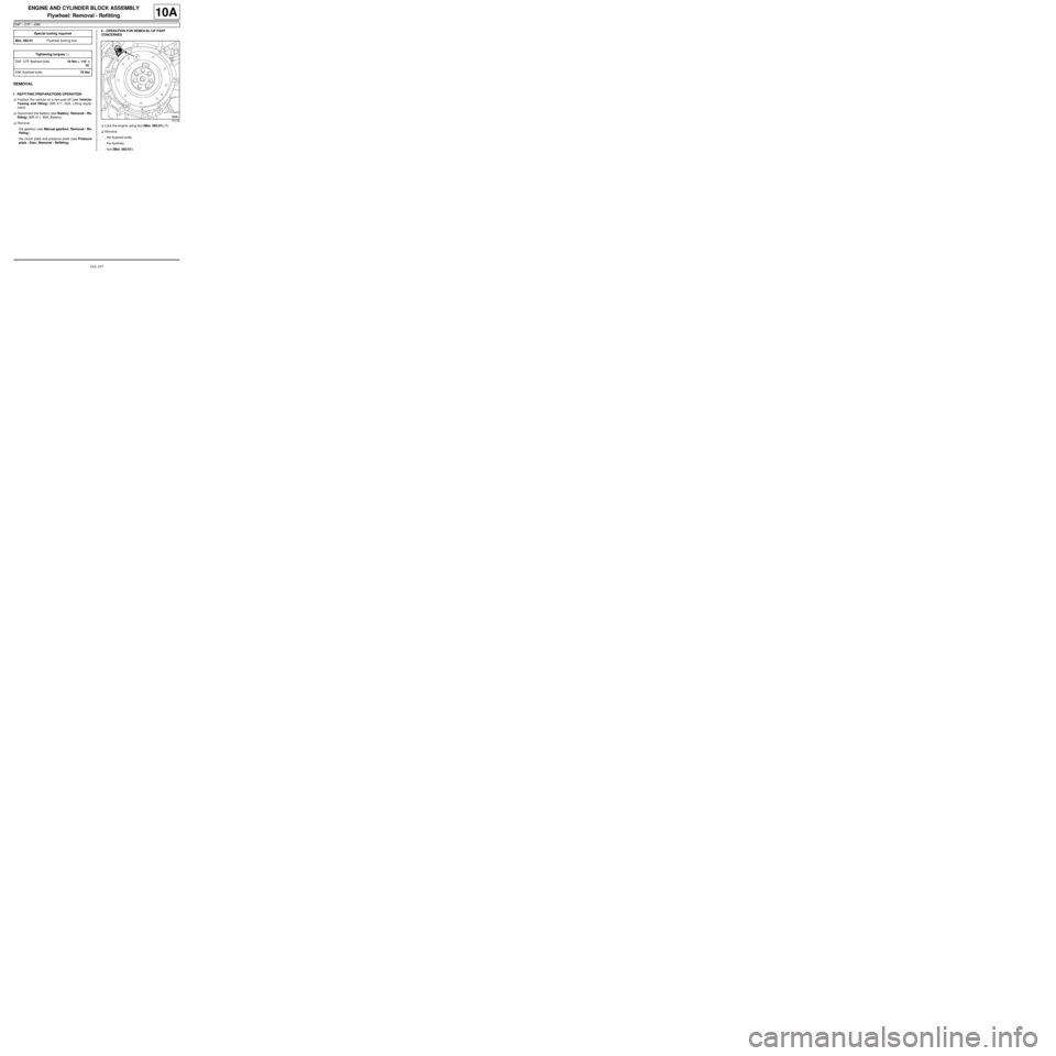
aLock the engine using tool (Mot. 582-01) (1) .
aRemove:
-the flywheel bolts,
-the flywheel,
-tool (Mot. 582-01). Special tooling required
Mot. 582-01Flywheel locking tool.
Tightening torquesm
D4F, D7F flywheel bolts18 Nm + 110˚ ±± ± ±
10˚
K9K flywheel bolts70 Nm
109158
Page 115 of 652

10A-109
ENGINE AND CYLINDER BLOCK ASSEMBLY
Flywheel: Removal - Refitting
D4F – D7F – K9K
10A
Tightening order
aObserve the tightening order.
aTorque and angle tighten, in order, the D4F, D7F fly-
wheel bolts (18 Nm + 110˚ ±± ± ±
10˚).
aTighten to torque and in order the K9K flywheel
bolts (70 Nm).
aRemove tool (Mot. 582-01).
III - FINAL OPERATION.
aRefit:
-the clutch plate and pressure plate (see Pressure
plate - Disc: Removal - Refitting) ,
-the gearbox (see Manual gearbox: Removal - Re-
fitting) .
aConnect the battery (see Battery: Removal - Refit-
ting) (MR 411, 80A, Battery).
23326
D4F – D7F
K9K
Page 116 of 652
10A-110
ENGINE AND CYLINDER BLOCK ASSEMBLY
Flywheel: Removal - Refitting
K4M
10A
REMOVAL
I - REMOVAL PREPARATION OPERATION
aPosition the vehicle on a two-post lift (see Vehicle:
Towing and lifting) (02A, Lifting equipment).
aRemove:
-the engine undertray,
-the battery (see Battery: Removal - Refitting)
(80A, Battery),
-the air filter unit (see 12A, Fuel mixture, Air filter
unit: Removal - Refitting, page 12A-13) ,
-the petrol injection computer (see 17B, Petrol in-
jection, Petrol injection computer: Removal -
Refitting, page 17B-20) ,
-the battery tray (see Battery tray: Removal - Re-
fitting) (80A, Battery),
-the front wheels (see Wheel: Removal - Refitting)
(35A, Wheels and tyres),
-the front wheel arch liners (see Front wheel arch
liner: Removal - Refitting) (55A, Exterior protec-
tion),
-the front bumper (see Front bumper: Removal -
Refitting) (55A, Exterior protection).
aDrain:
-the gearbox (see Manual gearbox oils: Draining -
Filling) (21A, Manual gearbox),
-the engine cooling system (see 19A, Cooling,
Cooling system: Draining - Refilling, page 19A-
9) ,
-the refrigerant circuit using a refrigerant charging
station (see Refrigerant circuit: Draining - Fill-
ing) (62A, Air conditioning).aRemove:
-the lower engine tie-bar (see 19D, Engine mount-
ing, Lower engine tie-bar: Removal - Refitting,
page 19D-18) ,
-the front axle subframe (see Front axle subframe:
Removal - Refitting) (31A, Front axle compo-
nents),
-the front left-hand wheel driveshaft (see Front left-
hand driveshaft: Removal - Refitting) (29A,
Driveshafts),
-the front right-hand wheel driveshaft (see Front
right-hand driveshaft: Removal - Refitting)
(29A, Driveshafts),
-the differential output seals (see Differential out-
put seal: Removal - Refitting) (21A, Manual gear-
box),
-the « engine - gearbox » assembly (see 10A, En-
gine and cylinder block assembly, Engine -
gearbox assembly: Removal - Refitting, page
10A-74) (21A, Manual gearbox),
-the manual gearbox (see Manual gearbox: Re-
moval - Refitting) ,
-the « pressure plate - disc » assembly (see Pres-
sure plate - Disc: Removal - Refitting) (20A,
Clutch).
II - REMOVAL OPERATION
aRemove:
-the flywheel bolts,
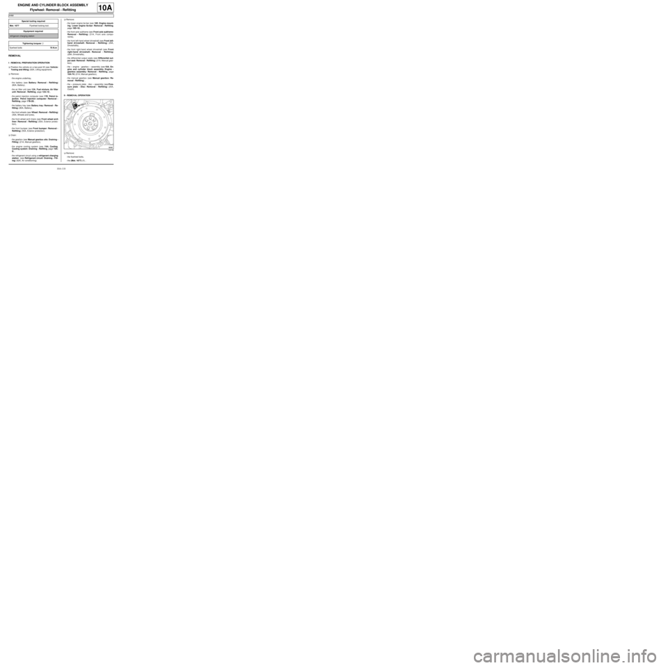
-the (Mot. 1677) (1) , Special tooling required
Mot. 1677Flywheel locking tool.
Equipment required
refrigerant charging station
Tightening torquesm
flywheel bolts70 N.m
109158
Page 117 of 652
10A-111
ENGINE AND CYLINDER BLOCK ASSEMBLY
Flywheel: Removal - Refitting
K4M
10A
-the flywheel.
REFITTING
I - REFITTING PREPARATION OPERATION
aUse SURFACE CLEANER (see Vehicle: Parts
and consumables for the repair) (04B, Consuma-
bles - Products) to clean and degrease:
-the flywheel bearing face if reusing,
-the crankshaft bearing face.
aAlways replace the flywheel bolts.
II - REFITTING OPERATION
aFit the flywheel.
aFit the new flywheel bolts without tightening them.
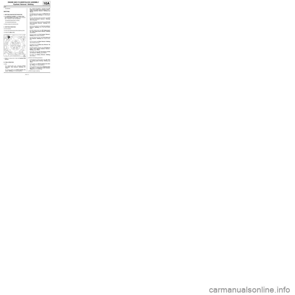
aPosition the (Mot. 1677).
aTighten to torque and in order the flywheel bolts
(70 N.m).
III - FINAL OPERATION
aRefit:
-the « pressure plate - disc » assembly (see Pres-
sure plate - Disc: Removal - Refitting) (20A,
Clutch),
-the manual gearbox (see Manual gearbox: Re-
moval - Refitting) (21A, Manual gearbox).-the « engine and gearbox » assembly (see 10A,
Engine and cylinder block assembly, Engine -
gearbox assembly: Removal - Refitting, page
10A-74) ,
-the differential output seals (see Differential out-
put seal: Removal - Refitting) (21A, Manual gear-
box),
-the front right-hand wheel driveshaft (see Front
right-hand driveshaft: Removal - Refitting)
(29A, Driveshafts),
-the front left-hand wheel driveshaft (see Front left-
hand driveshaft: Removal - Refitting) (29A,
Driveshafts),
-the front axle subframe (see Front axle subframe:
Removal - Refitting) (31A, Front axle compo-
nents),
-the lower engine tie-bar (see 19D, Engine mount-
ing, Lower engine tie-bar: Removal - Refitting,
page 19D-18) ,
-the front bumper (see Front bumper: Removal -
Refitting) (55A, Exterior protection),
-the front wheel arch liners (see Front wheel arch
liner: Removal - Refitting) (55A, Exterior protec-
tion),
-the front wheels (see Wheel: Removal - Refitting)
(35A, Wheels and tyres),
-the battery tray (see Battery tray: Removal - Re-
fitting) (80A, Battery),
-the petrol injection computer (see 17B, Petrol in-
jection, Petrol injection computer: Removal -
Refitting, page 17B-20) ,
-the air filter unit (see 12A, Fuel mixture, Air filter
unit: Removal - Refitting, page 12A-13) ,
-the battery (see Battery: Removal - Refitting)
(80A, Battery).
aPerform the following operations:
-fill and bleed the cooling system (see 19A, Cool-
ing, Cooling system: Draining - Refilling, page
19A-9) ,
-fill the gearbox (see Manual gearbox oils: Drain-
ing - Filling) (21A, Manual gearbox).
-fill the refrigerant circuit using a refrigerant charg-
ing station (see Refrigerant circuit: Draining -
Filling) (62A, Air conditioning).
aRefit the engine undertray.
109158
Page 122 of 652
11A-5
TOP AND FRONT OF ENGINE
Accessories belt: Removal - Refitting
K9K, and AIR CONDITIONING
11A
PARTS AND CONSUMABLES FOR THE
REPAIR WORK
aParts always to be replaced:
-accessories belt,
-accessories belt tensioning roller,
-accessories belt tensioning roller bolt,
-axle sub-frame bolts.
REMOVAL
I - REMOVAL PREPARATION OPERATION
aPosition the vehicle on a two-post lift (see Vehicle:
Towing and lifting) (MR 411, 02A, Lifting equip-
ment).
aDisconnect the battery (see ) (MR 411, 80A, Bat-
tery).
aRemove:
-the wiper arms (see Windscreen wiper arm: Re-
moval - Refitting) (MR 411, 85A, Wipers - Wash-
ers),
-the scuttle panel grille (see Scuttle panel grille:
Removal - Refitting) (MR 412, 56A, Exterior
equipment),
-the scoop under the scuttle panel grille (see Scoop
under the scuttle panel grille: Removal - Refit-
ting) (MR 412, 56A, Exterior equipment).
-the front right-hand wheel (see Wheel: Removal -
Refitting) (MR 411, 35A, Wheels and tyres),
-the front right-hand wheel arch liner (see Front
wheel arch liner: Removal - Refitting) (MR 412,
55A, Exterior protection),
-the front bumper (see Front bumper: Removal -
Refitting) (MR 412, 55A, Exterior protection),
-the left-hand and right-hand headlights (see Halo-
gen headlight: Removal - Refitting) (MR 411,
80B, Headlights).aRemove:
-the air filter inlet air pipe bolt from the front upper
cross member,
-the expansion bottle bolt from the front upper cross
member,
-the cooling radiator retaining bracket bolt from the
front upper cross member.
aUnclip and then remove from the front upper cross
member:
-the air filter inlet air pipe,
-the expansion bottle.
aRemove the bonnet catch bolts.
aRemove the « cable - bonnet catch » assembly.
aRemove:
-the front upper cross member (see Front upper
cross member: Removal - Refitting) (MR 412,
42A, Upper front structure),
-the air conditioning pipe clip from the right-hand
headlight carrier panel,
-the right-hand suspended engine mounting (see
19D, Engine mounting, Right-hand suspended
engine mounting: Removal - Refitting, page
19D-13) .
II - OPERATION FOR REMOVAL OF PART
CONCERNED
1 - Removing the accessories belt
aRaise the engine using the (Mot. 1672) to access
the tensioning roller.
aRelax the accessories belt using a ratchet, an exten-
sion and a 16 mm socket.
aRemove the belt, passing it over its slot between the
headlight carrier panel and the alternator pulley.
aLower the engine using tool (Mot. 1672). Special tooling required
Mot. 1672Low er engine support.
Tightening torquesm
tensioning roller bolt40 Nm
alter nator bolts25 Nm
Note:
Shift the engine forwards slightly by hand to facil-
itate setting up the tools.
Page 125 of 652
11A-8
TOP AND FRONT OF ENGINE
Accessories belt: Removal - Refitting
D4F, and 772 or 780 or 782, and AIR CONDITIONING – D7F, and AIR CONDITIONING
11A
REMOVAL
I - REMOVAL PREPARATION OPERATION
aPosition the vehicle on a two-post lift (see Vehicle:
Towing and lifting) (02A, Lifting equipment).
aDisconnect the battery (see Battery: Removal - Re-
fitting) (80A, Battery).
aRemove:
-the front right-hand wheel (see Wheel: Removal -
Refitting) (35A, Wheels and tyres),
-the front right-hand wheel arch liner clips,
-the front right-hand wheel arch liner bolts,
aRemove the lower section of the front right-hand
wheel arch liner.II - OPERATION FOR REMOVAL OF PART
CONCERNED
a
aRemove the accessories belt tensioning roller pro-
tector.
aUndo the accessories belt tensioning roller bolt.
aRemove:
-the accessories belt,
-the accessories belt tensioning roller bolt,
-the accessories belt tension wheel.
REFITTING
I - REFITTING PREPARATION OPERATION
aUse a brush to remove any deposits from the crank-
shaft pulley V-grooves.
aparts always to be replaced: Accessories belt.
aparts always to be replaced: Accessories belt
tensioning roller. Special tooling required
Mot. 1715Belt tension checking tool
(frequency indicator).
Mot. 1505Belt tension setting tool (fre-
quency meter)
Equipment required
open-ended spanner
Tightening torquesm
tensioning roller bolt44 N.m
120775
109766
IMPORTANT
Wear cut-resistant gloves during the operation.
WARNING
Only use brushes with plastic or non-corrosive
metal (br ass) bristles.
Page 126 of 652
11A-9
TOP AND FRONT OF ENGINE
Accessories belt: Removal - Refitting
D4F, and 772 or 780 or 782, and AIR CONDITIONING – D7F, and AIR CONDITIONING
11A
aparts always to be replaced: Accessories ten-
sioning roller bolt (to be replaced by the hexagonal
head bolt, part no. 77 03 101 075).
aRefit:
-the new accessories belt tensioning roller,
-the accessories belt tensioning roller hexagonal-
head bolt
II - REFITTING OPERATION FOR PART
CONCERNED
aRefit the accessories belt.
aTension the accessories belt by turning the tension-
ing roller anti-clockwise using an open-jawed span-
ner.
aAdjust the accessories belt tension using the (Mot.
1715) or (Mot. 1505).aFit the accessories belt tensioning roller bolt without
tightening it, maintaining the accessories belt ten-
sion at a setting value of 274 Hz ±± ± ±
4.
aTorque tighten the tensioning roller bolt (44 N.m)
using a torque wrench fitted with a open-ended
spanner, maintaining the accessories belt tension
at the adjustment value of 277 Hz ±± ± ±
5 using an open-
jawed spanner.
aTurn the engine three revolutions clockwise (timing
end) to position the accessories belt correctly.
aCheck the accessories belt tension using the (Mot.
1715) or (Mot. 1505).
aIf the accessory belt tension is outside permitted tol-
erance values, readjust it.
aRefit the accessories belt tension wheel protector.
III - FINAL OPERATION
aFit the lower section of the front right-hand wheel
arch liner.
aRefit:
-the front right-hand wheel arch liner bolts,
-the front right-hand wheel arch liner clips,
-the front right-hand wheel (see Wheel: Removal -
Refitting) (35A, Wheels and tyres).
aConnect the battery (see Battery: Removal - Refit-
ting) (80A, Battery).
112339
120524
Page 127 of 652
11A-10
TOP AND FRONT OF ENGINE
Accessories belt: Removal - Refitting
K9K, and STANDARD HEATING
11A
PARTS AND CONSUMABLES FOR THE
REPAIR WORK
aParts always to be replaced:
-accessories belt,
-accessories belt tensioning roller,
-accessories belt tensioning roller bolt
-the air conditioning compressor substitute pulley,
-axle sub-frame bolts.
REMOVAL
I - REMOVAL PREPARATION OPERATION
aPosition the vehicle on a two-post lift (see Vehicle:
Towing and lifting) (MR 411, 02A, Lifting equip-
ment).
aDisconnect the battery (see ) (MR 411, 80A, Bat-
tery).
aRemove:
-the front right-hand wheel (see Wheel: Removal -
Refitting) (MR 411, 35A, Wheels and tyres),
-the front right-hand wheel arch liner (see Front
wheel arch liner: Removal - Refitting) (MR 412,
55A, Exterior protection),
-the front bumper (see Front bumper: Removal -
Refitting) (MR 412, 55A, Exterior protection),
-the left-hand and right-hand headlights (see Halo-
gen headlight: Removal - Refitting) (MR 411,
80B, Headlights).aRemove:
-the air filter inlet air pipe bolt from the front upper
cross member,
-the expansion bottle bolt from the front upper cross
member,
-the cooling radiator retaining bracket bolt from the
front upper cross member.
aUnclip and then remove from the front upper cross
member:
-the air filter inlet air pipe,
-the expansion bottle.
aRemove the bonnet catch bolts.
aRemove the « cable - bonnet catch » assembly.
aRemove the front upper cross member (see Front
upper cross member: Removal - Refitting) (MR
412, 42A, Upper front structure).
II - OPERATION FOR REMOVAL OF PART
CONCERNED
1 - Removing the accessories belt
aRelax the accessories belt using a 16 mm spanner.
aRemove the accessories belt from the air condition-
ing compressor substitute pulley.
aRemove the accessories belt, passing it over its slot
between the RH side member and the crankshaft
accessories and alternator pulleys.
aDiscard the accessories belt
2 - Removing the tensioning roller and the air
conditioning compressor substitute pulley
a
aDisconnect the connector on the alternator.
aRemove the nut from the alternator harness.
aMove the alternator harness to one side.
aRemove the alternator upper bolt.
aLoosen the alternator lower bolt.
aRemove the alternator with its lower bolt fitted. Tightening torquesm
air conditioning com-
pressor substitute pul-
ley bolts25 Nm
tensioning roller bolt40 Nm
bolts mounting the mul-
tifunction support on the
cylinder block44 Nm
bolt mounting the multi-
function support on the
sump25 Nm
alter nator bolts25 Nm
Note:
The tensioning roller and air conditioning com-
pressor substitute pulley must be replaced every
time the accessor ies belt is replaced.
Page 130 of 652
11A-13
TOP AND FRONT OF ENGINE
Accessories belt: Removal - Refitting
D4F, and 780 or 782, and STANDARD HEATING
11A
a
REMOVAL
I - REMOVAL PREPARATION OPERATION
aPosition the vehicle on a two-post lift (see Vehicle:
Towing and lifting) (02A, Lifting equipment).aRemove:
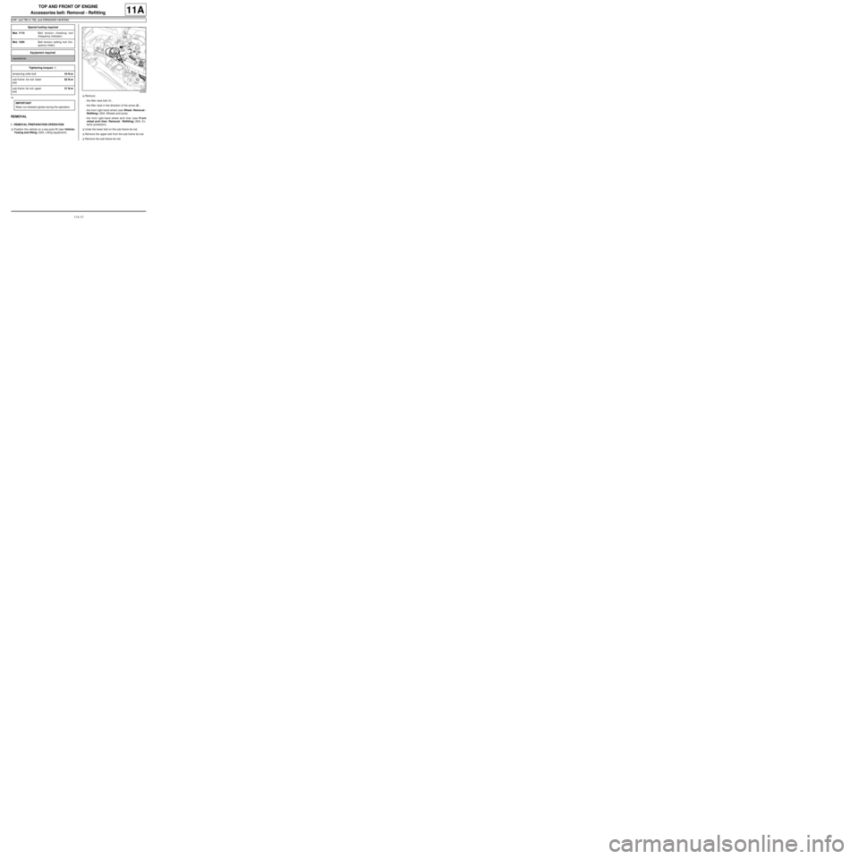
-the filler neck bolt (1) ,
-the filler neck in the direction of the arrow (2) ,
-the front right-hand wheel (see Wheel: Removal -
Refitting) (35A, Wheels and tyres),
-the front right-hand wheel arch liner (see Front
wheel arch liner: Removal - Refitting) (55A, Ex-
terior protection).
aUndo the lower bolt on the sub-frame tie-rod.
aRemove the upper bolt from the sub-frame tie-rod.
aRemove the sub-frame tie-rod. Special tooling required
Mot. 1715Belt tension checking tool
(frequency indicator).
Mot. 1505Belt tension setting tool (fre-
quency meter)
Equipment required
repositioner
Tightening torquesm
tensioning roller bolt44 N.m
sub-frame tie-rod lower
bolt62 N.m
sub-frame tie-rod upper
bolt21 N.m
IMPORTANT
Wear cut-resistant gloves during the operation.
122392