air condition RENAULT TWINGO RS 2009 2.G Engine And Peripherals Owner's Guide
[x] Cancel search | Manufacturer: RENAULT, Model Year: 2009, Model line: TWINGO RS, Model: RENAULT TWINGO RS 2009 2.GPages: 652
Page 137 of 652
11A-20
TOP AND FRONT OF ENGINE
Crankshaft accessories pulley: Removal - Refitting
D4F or D7F, and AIR CONDITIONING or STANDARD HEATING
11A
REMOVAL
I - REMOVAL PREPARATION OPERATION
aPosition the vehicle on a two-post lift (see Vehicle:
Towing and lifting) (02A, Lifting equipment).
aRemove:
-the engine undertray,
-the front right-hand wheel (see Wheel: Removal -
Refitting) (35A, Wheels and tyres),
-the front right-hand wheel arch liner (see Front
wheel arch liner: Removal - Refitting) (55A, Ex-
terior protection).
-the accessories belt (see 11A, Top and front of
engine, Accessories belt: Removal - Refitting,
page 11A-3) .II - OPERATION FOR REMOVAL OF PART
CONCERNED
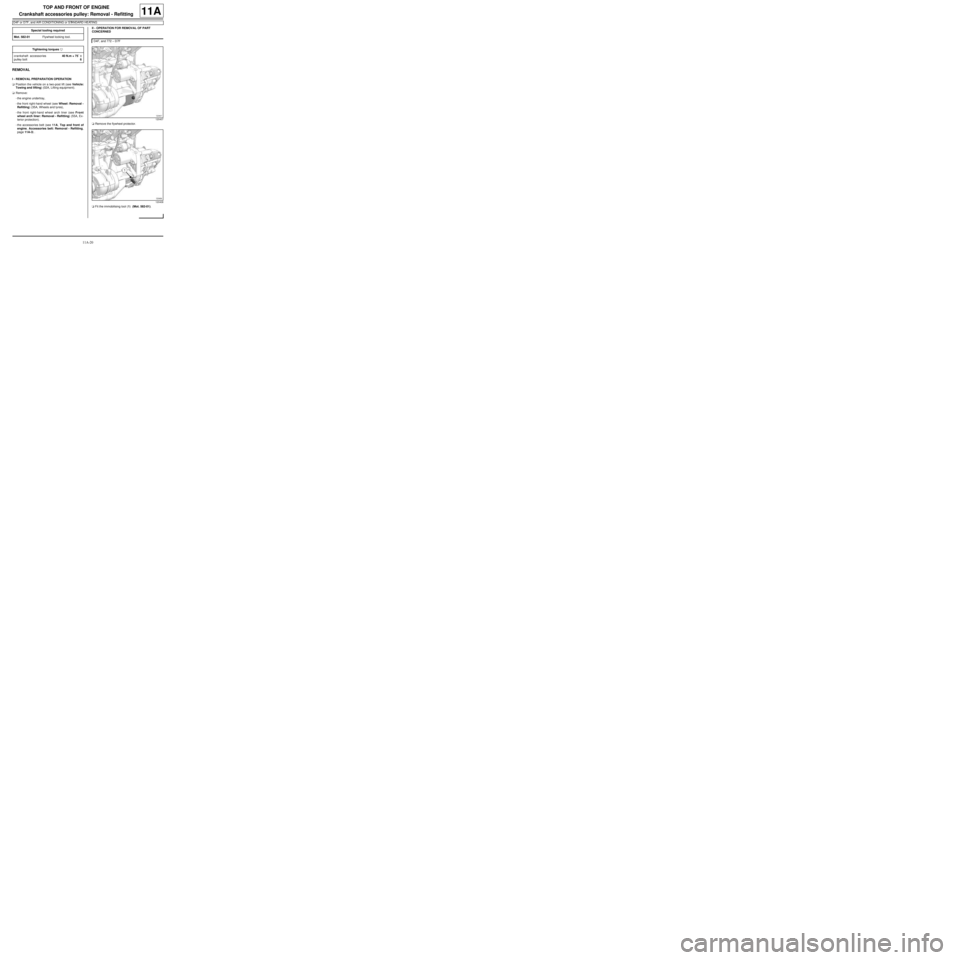
aRemove the flywheel protector.
aFit the immobilising tool (1) (Mot. 582-01). Special tooling required
Mot. 582-01Flywheel locking tool.
Tightening torquesm
crankshaft accessories
pulley bolt40 N.m + 75˚ ±± ± ±
6
D4F, and 772 – D7F
120407
120408
Page 138 of 652
11A-21
TOP AND FRONT OF ENGINE
Crankshaft accessories pulley: Removal - Refitting
D4F or D7F, and AIR CONDITIONING or STANDARD HEATING
11A
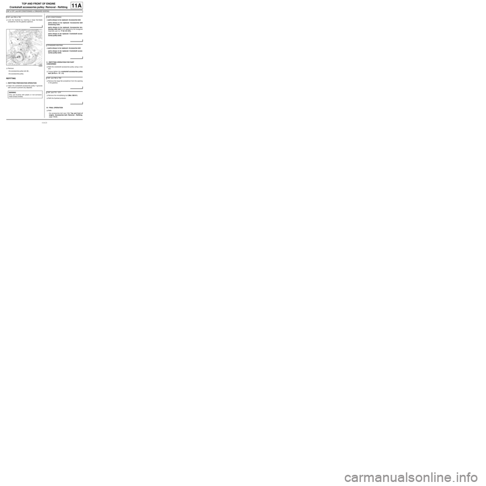
aLock the flywheel by inserting a large flat-blade
screwdriver into the gearbox aperture.
aRemove:
-the accessories pulley bolt (2) ,
-the accessories pulley.
REFITTING
I - REFITTING PREPARATION OPERATION
aClean the crankshaft accessories pulley V-grooves
with a brush to prevent any deposits.aparts always to be replaced: Accessories belt,
parts always to be replaced: Accessories belt
tensioning roller,
parts always to be replaced: Accessories ten-
sioning roller bolt (to be replaced by the hexagonal
head bolt, part no. 77 03 101 075),
parts always to be replaced: Crankshaft acces-
sories pulley bolts.
aparts always to be replaced: Accessories belt,
parts always to be replaced: Crankshaft acces-
sories pulley bolts.
II - REFITTING OPERATION FOR PART
CONCERNED
aRefit the crankshaft accessories pulley using a new
bolt.
aTorque tighten the crankshaft accessories pulley
bolt (40 N.m + 75˚ ±± ± ±
6).
aRemove the large flat screwdriver from the opening
in the gearbox.
aRemove the immobilising tool (Mot. 582-01).
aRefit the flywheel protector.
III - FINAL OPERATION
aRefit:
-the accessories belt (see 11A, Top and front of
engine, Accessories belt: Removal - Refitting,
page 11A-3) , D4F, and 780 or 782
122665
WARNING
Only use brushes with plastic or non-corrosive
metal (brass) bristles.
AIR CONDITIONING
STANDARD HEATING
D4F, and 780 or 782
D4F, and 772 – D7F
Page 139 of 652
11A-22
TOP AND FRONT OF ENGINE
Crankshaft accessories pulley: Removal - Refitting
D4F or D7F, and AIR CONDITIONING or STANDARD HEATING
11A
-the front right-hand wheel arch liner (see Front
wheel arch liner: Removal - Refitting) (55A, Ex-
terior protection),
-the front right-hand wheel (see Wheel: Removal -
Refitting) (35A, Wheels and tyres),
-the engine undertray.
Page 280 of 652
12A-15
FUEL MIXTURE
Air filter unit: Removal - Refitting
K9K
12A
REMOVAL
I - REFITTING OPERATION FOR PART
CONCERNED
aSlide the air filter box towards the gearbox side.
aCheck the condition of the air filter box mountings,
replace them if necessary.
aClip:
-the air filter box onto its mountings,
-the air filter air outlet pipe to the air filter.
aTighten the air pipe clip on the air filter outlet.
aRefit the air filter air inlet pipe on the vehicle.
aPosition the turbocharger pressure sensor on the air
filter box.
aRefit the bolt mounting the turbocharger pressure
sensor on the air filter box.
aConnect the connectors:
-of the inlet air temperature sensor,
-of the turbocharging pressure sensor,
-of the flow sensor,
-of the EGR.
aClip on the air filter box harnesses.
aClip the air filter inlet air pipe to the air filter box.
II - FINAL OPERATION.
aRefit the engine cover.Note:
Ensure that the centring lug of the box is fully
inserted in the cylinder head.
Page 295 of 652
12A-30
FUEL MIXTURE
Inlet distributor: Removal - Refitting
D7F
12A
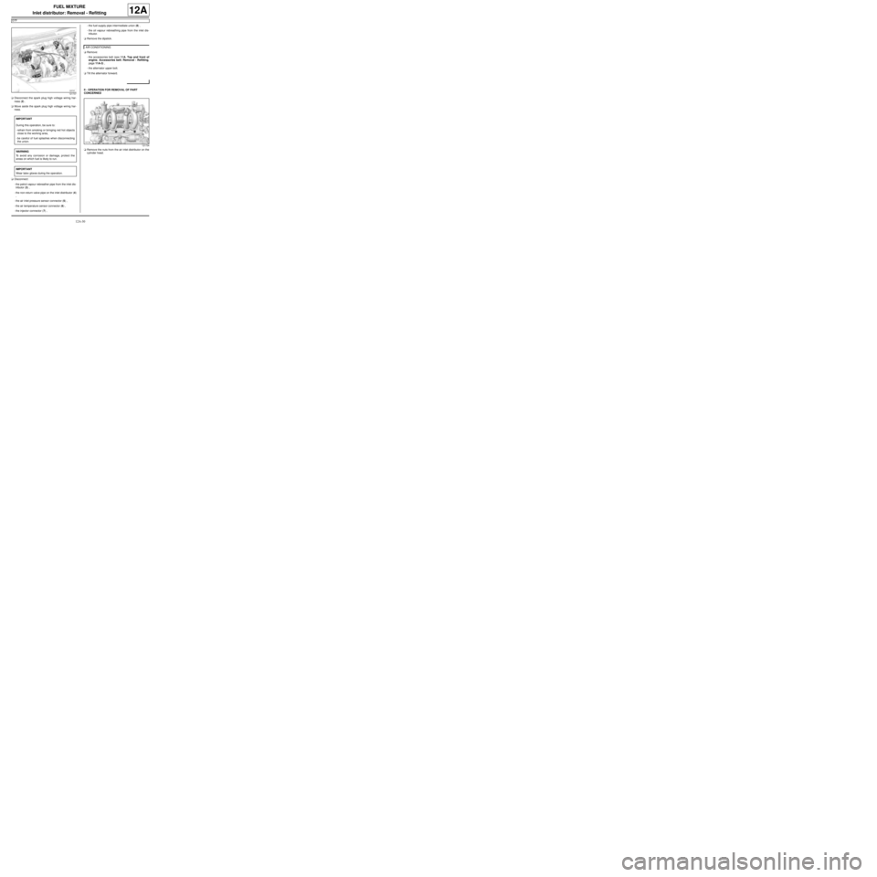
aDisconnect the spark plug high voltage wiring har-
ness (2) .
aMove aside the spark plug high voltage wiring har-
ness.
aDisconnect:
-the petrol vapour rebreather pipe from the inlet dis-
tributor (3) ,
-the non-return valve pipe on the inlet distributor (4)
,
-the air inlet pressure sensor connector (5) ,
-the air temperature sensor connector (6) ,
-the injector connector (7) ,-the fuel supply pipe intermediate union (8) ,
-the oil vapour rebreathing pipe from the inlet dis-
tributor.
aRemove the dipstick.
aRemove:
-the accessories belt (see 11A, Top and front of
engine, Accessories belt: Removal - Refitting,
page 11A-3) ,
-the alternator upper bolt.
aTilt the alternator forward.
II - OPERATION FOR REMOVAL OF PART
CONCERNED
aRemove the nuts from the air inlet distributor on the
cylinder head.
121737
IMPORTANT
During this operation, be sure to:
-refrain from smoking or bringing red hot objects
close to the working area,
-be careful of fuel splashes when disconnecting
the union.
WARNING
To avoid any corrosion or damage, protect the
areas on which fuel is likely to run.
IMPORTANT
Wear latex gloves during the operation.
AIR CONDITIONING
121734
Page 297 of 652
12A-32
FUEL MIXTURE
Inlet distributor: Removal - Refitting
D7F
12A
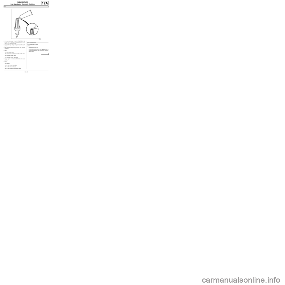
aIt is essential to apply a bead of FLUORSTAR 2L
grease with a diameter of 2 mm around the inner
edge of the high tension caps.
aConnect the high voltage wiring harness to the spark
plugs.
aClip the high voltage wiring harness onto the inlet
distributor.
aRefit:
-the intermediate plate,
-the intermediate bracket bolts on the throttle valve,
-the motorised throttle valve,
-the motorised throttle valve bolts.
aTorque tighten the motorised throttle valve bolts
(10 N.m)
aRefit:
-the dipstick,
-the air filter unit air outlet pipe.
-the air filter unit air inlet pipe,
-the air inlet scoop on the front end panel.aFit the alternator in place.
aRefit:
-the alternator upper bolt,
-the accessories belt (see 11A, Top and front of
engine, Accessories belt: Removal - Refitting,
page 11A-3) .
106640
AIR CONDITIONING
Page 326 of 652
12B-1
TURBOCHARGING
Turbocharging: Precautions for the repair
D4F or K9K
12B
I - TURBOCHARGER: GENERAL INSTRUCTIONS
For the turbocharging pressure regulator check (see
Fault finding - Tests) (Technical Note 3419A, 12B,
Turbocharging).
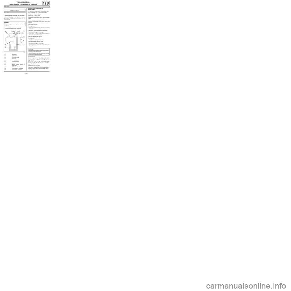
II - TURBOCHARGER CIRCUIT DIAGRAMIII - APPLICATION CONDITIONS OF
INSTRUCTIONS
The instructions below must be followed when repla-
cing a turbocharger due to mechanical damage:
-damage to the bearing system,
-broken shaft or turbine wheel,
-compressor wheel rubbing against the turbocharger
casing,
-broken or damaged compressor wheel,
-extensive clogging of the turbine wheel casing (hard
deposits).
FOR THE AIR CIRCUIT:
-Consequences:
•swarf or metal objects in the turbocharger inlet and
outlet pipes,
•oil in the air circuit (collected in the intercooler).
-Risks (after replacing the turbocharger):
•metal objects sucked in by the compressor wheel
(destruction of the turbocharger).
FOR THE LUBRICATION CIRCUIT:
-Consequences:
•swarf found in the engine oil circuit,
•circulation of swarf within the circuit.
-Risks (after replacing the turbocharger):
•premature wear on the bearing system (destruction
of turbocharger).
INSTRUCTIONS:
-Drain the engine oil (see 10A, Engine and cylinder
block assembly, Engine oil: Draining - Refilling,
page 10A-22)
-Replace the oil filter (see 10A, Engine and cylinder
block assembly, Oil filter: Removal - Refitting,
page 10A-29) .
-Replace the seals and fittings,
-Carry out the following only if the compressor wheel is
broken or rubbing against the turbocharger casing:
•Drain the intercooler, Equipment required
par ts washer
WARNING
The turbocharger pressure regulator rod must not
be adjusted.
112666
(1) Air filter unit
(2) Air flowmeter
(3) Compressor wheel
(4) Intercooler
(5) Inlet distributor
(6) Exhaust manifold
(7) Turbine wheel
(8) Bearing system (bearing +
wheel shaft)
(A) Air filter box air outlet pipe
(B) Turbocharger air outlet pipe
(C) Intercooler air outlet pipe
WARNING
Metal objects may enter the oil and air circuits as a
result of a broken turbocharger.
Failure to follow the INSTRUCTIONS listed will lead
to the turbocharger breaking again.
Page 362 of 652
13B-1
DIESEL INJECTION
Diesel injection: Precautions for the repair
K9K
13B
I - RISKS RELATING TO CONTAMINATION
The high-pressure direct injection system is highly sen-
sitive to contamination. The risks caused by contami-
nation are:
-damage to or destruction of the high pressure injec-
tion system,
-a component seizing,
-a component not being properly sealed.
All After-Sales operations must be performed under
very clean conditions. Having carried out an operation
in good conditions means that no impurities (particles a
few microns in size) have penetrated the system during
dismantling.
The cleanliness principle must be applied from the filter
to the injectors.
What are the sources of contamination?
-metal or plastic swarf,
-paint,
-fibres:
•cardboard,
•brushes,
•paper,
•clothing,
•cloth,
-foreign bodies such as hair,
-ambient air,
-etc.
1 - Cleaning cloths
Use lint-free cleaning cloths (see Vehicle: Parts and
consumables for the repair) (04B, Consumables -
Products).
It is prohibited to use cloths or ordinary paper towels:
these produce lint and lose fibres, which then contami-
nate the fuel circuit.
Each cloth must only be used once.2 - Blanking plugs
The blanking plugs are used to cap the fuel circuit once
it is opened and to therefore prevent contaminants
from entering.
A set of blanking plugs should be used once only and
used plugs must be discarded after use: once used,
the plugs are soiled and cleaning them is not sufficient
to make them reusable.
Unused plugs must also be discarded and must not be
used when carrying out work on an injection system.
Part number for set of blanking plugs: (see Vehicle:
Parts and consumables for the repair) (04B, Con-
sumables - Products).
3 - Protective bags
Use hermetically-resealable plastic bags, using adhe-
sive tape, for example, to store components which will
be refitted and reused. Stored parts will therefore be
less subject to the risk of contamination.
These are single-use bags: after use they must be dis-
carded.
4 - Cleaning products
Two cleaning products can be used:
-an injector cleaner (see Vehicle: Parts and consum-
ables for the repair) (04B, Consumables - Products),
-an aerosol spray brake cleaner (see Vehicle: Parts
and consumables for the repair) (04B, Consum-
ables - Products).
To use the injector cleaner, be sure to have a clean
brush in good condition (the brush must not lose any
bristles) as well as a clean container which has no im-
purities in it. WARNING
Do not clean the engine with a high pressure
cleaner to prevent damaging the connections.
Note:
There is no specific set of blanking plugs for S9U
and S9W engines. In order to comply with the
cleanliness recommendations, use plugs that are
compatible with the blanking plug sets for F9Q,
G9U, G9T or ZD3 engines.
Note:
Use a new injector cleaner each time work is car-
ried out (a used cleaning agent will contain impuri-
ties).
Page 384 of 652
13B-23
DIESEL INJECTION
High pressure pump: Removal - Refitting
K9K
13B
REFITTING
I - REFITTING PREPARATION OPERATION
a
aparts always to be replaced: Injection pump
sprocket nut
aparts always to be replaced: Front sub-frame
bolt
II - REFITTING OPERATION FOR PART
CONCERNED
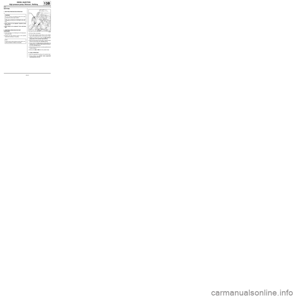
aCheck that there is an indexing pin on the high pres-
sure pump shaft.
aPosition the high pressure pump on the cylinder
head whilst inserting it in its pulley.aFit the air filter unit bracket.
aFit the high pressure pump bolts on the cylinder
head, without tightening them, until contact is made.
aTighten to torque and in order the high pressure
pump bolts on the cylinder head (23 N.m).
aRefit the high pressure pump pulley, holding the high
pressure pump pulley with a 32 mm spanner.
aTorque tighten the high pressure pump pulley nut
(70 N.m) while holding the high pressure pump pul-
ley using a 32 mm spanner.
aCheck that the timing belt is correctly positioned and
in good condition.
aRemove the (Mot. 1606) from the cylinder head.
III - FINAL OPERATION
aRefit the suspended mounting on the cylinder head.
aTorque tighten the cylinder head suspended
mounting bolts (25 N.m). WARNING
Do not remove the blanking plugs from each
component until the last moment.
Also, do not remove the components from their
packaging until they are to be fitted to the vehi-
cle.
Note:
Check that the high pressure pump shaft is cor-
rectly orientated in relation to the pulley.
102085
Page 419 of 652
14A-1
ANTIPOLLUTION
Oil vapour rebreathing circuit: Descriptions
K9K
14A
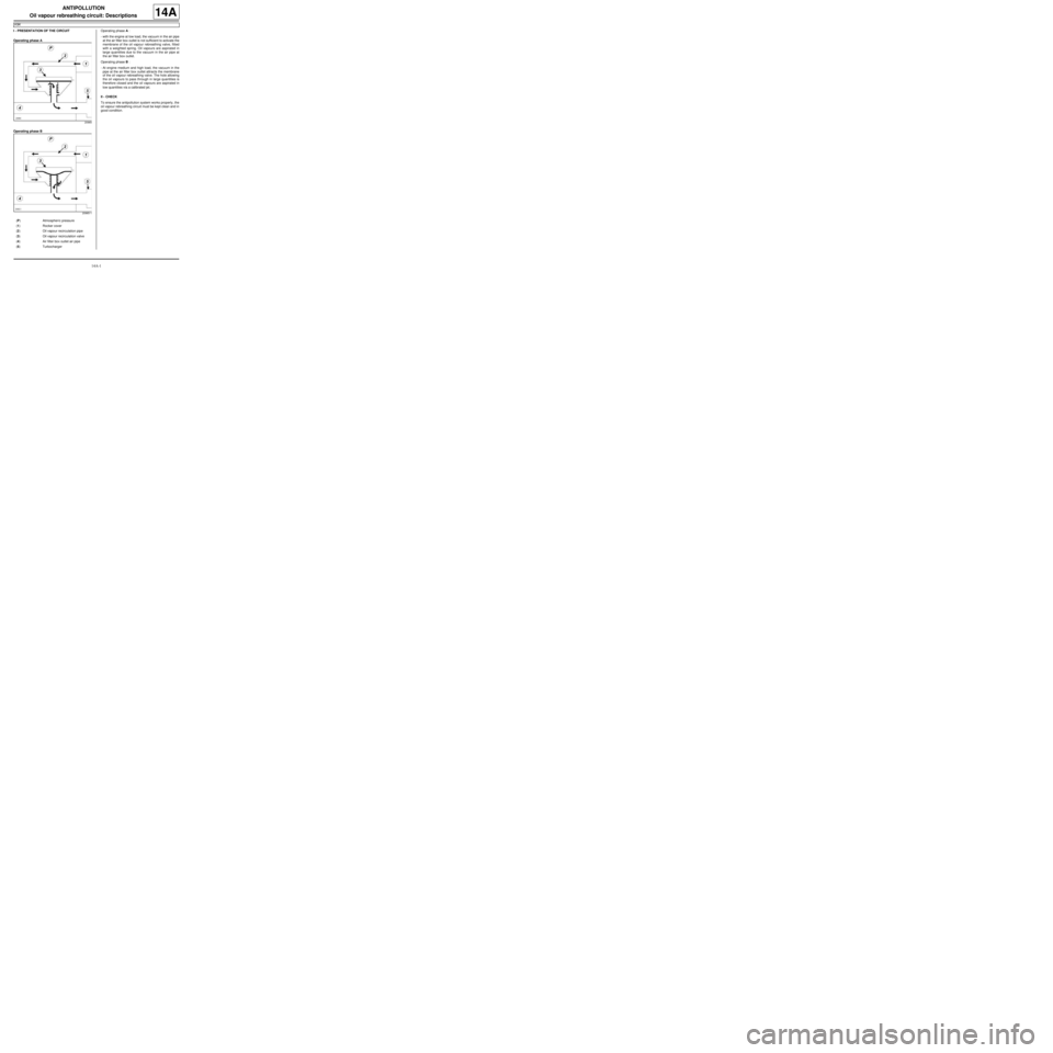
I - PRESENTATION OF THE CIRCUIT
Operating phase A
Operating phase BOperating phase A :
-with the engine at low load, the vacuum in the air pipe
at the air filter box outlet is not sufficient to activate the
membrane of the oil vapour rebreathing valve, fitted
with a weighted spring. Oil vapours are aspirated in
large quantities due to the vacuum in the air pipe at
the air filter box outlet.
Operating phase B :
-At engine medium and high load, the vacuum in the
pipe at the air filter box outlet attracts the membrane
of the oil vapour rebreathing valve. The hole allowing
the oil vapours to pass through in large quantities is
therefore closed and the oil vapours are aspirated in
low quantities via a calibrated jet.
II - CHECK
To ensure the antipollution system works properly, the
oil vapour rebreathing circuit must be kept clean and in
good condition.
20965
20965-1
(P) Atmospher ic pressure
(1) Rocker cover
(2) Oil vapour recirculation pipe
(3) Oil vapour recirculation valve
(4) Air filter box outlet air pipe
(5) Turbocharger